
You also want an ePaper? Increase the reach of your titles
YUMPU automatically turns print PDFs into web optimized ePapers that Google loves.
Speed correction factor c 3<br />
Table 3<br />
Fatigue correction factor c 6<br />
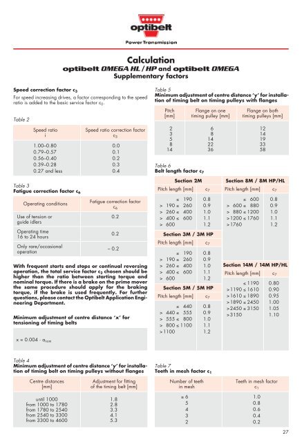
Calculation<br />
optibelt OMEGA HL /HP and optibelt OMEGA<br />
Supplementary factors<br />
For speed increasing drives, a factor corresponding to the speed<br />
ratio is added to the basic service factor c 0.<br />
Table 2<br />
Speed ratio Speed ratio correction factor<br />
i c 3<br />
1.00–0.80 0.0<br />
0.79–0.57 0.1<br />
0.56–0.40 0.2<br />
0.39–0.28 0.3<br />
0.27 and less 0.4<br />
Operating conditions<br />
Fatigue correction factor<br />
c 6<br />
Use of tension or 0.2<br />
guide idlers<br />
Operating time<br />
16 to 24 hours<br />
Only rare/occasional<br />
operation<br />
– 0.2<br />
With frequent starts and stops or continual reversing<br />
operation, the total service factor c 2 chosen should be<br />
higher than the ratio between starting torque and<br />
nominal torque. If there is a brake on the prime mover<br />
the same procedure should apply for the braking<br />
torque, if the brake is used frequently. For further<br />
questions, please contact the Optibelt Application Engineering<br />
Department.<br />
Table 4<br />
Minimum adjustment of centre distance ‘y’ for installation<br />
of timing belt on timing pulleys without flanges<br />
Centre distances<br />
[mm]<br />
0.2<br />
Minimum adjustment of centre distance ‘x’ for<br />
tensioning of timing belts<br />
x = 0.004 · a nom<br />
Adjustment for fitting<br />
of the timing belt [mm]<br />
until 1000 1.8<br />
from 1000 to 1780 2.8<br />
from 1780 to 2540 3.3<br />
from 2540 to 3300 4.1<br />
from 3300 to 4600 5.3<br />
Table 5<br />
Minimum adjustment of centre distance ‘y’ for installation<br />
of timing belt on timing pulleys with flanges<br />
Pitch<br />
[mm]<br />
Flange on one<br />
timing pulley [mm]<br />
2 6 12<br />
3 8 14<br />
5 14 19<br />
8 22 33<br />
14 36 58<br />
Table 6<br />
Belt length factor c 7<br />
Section 2M<br />
Pitch length [mm] c 7<br />
≤ 190 0.8<br />
> 190 ≤ 260 0.9<br />
> 260 ≤ 400 1.0<br />
> 400 ≤ 600 1.1<br />
> 600 1.2<br />
Section 3M / 3M HP<br />
Pitch length [mm] c7 ≤ 190 0.8<br />
> 190 ≤ 260 0.9<br />
> 260 ≤ 400 1.0<br />
> 400 ≤ 600 1.1<br />
> 600 1.2<br />
Section 5M / 5M HP<br />
Pitch length [mm] c7 ≤ 440 0.8<br />
> 440 ≤ 555 0.9<br />
> 555 ≤ 800 1.0<br />
> 800 ≤ 1100 1.1<br />
>1100 1.2<br />
Table 7<br />
Teeth in mesh factor c 1<br />
Number of teeth Teeth in mesh factor<br />
in mesh c 1<br />
≥ 6 1.0<br />
5 0.8<br />
4 0.6<br />
3 0.4<br />
2 0.2<br />
Flange on both<br />
timing pulleys [mm]<br />
Section 8M / 8M HP/HL<br />
Pitch length [mm] c7 ≤ 600 0.8<br />
> 600 ≤ 880 0.9<br />
> 880 ≤ 1200 1.0<br />
>1200 ≤ 1760 1.1<br />
>1760 1.2<br />
Section 14M / 14M HP/HL<br />
Pitch length [mm] c7 ≤ 1190 0.80<br />
>1190 ≤ 1610 0.90<br />
>1610 ≤ 1890 0.95<br />
>1890 ≤ 2450 1.00<br />
>2450 ≤ 3150 1.05<br />
>3150 1.10<br />
27