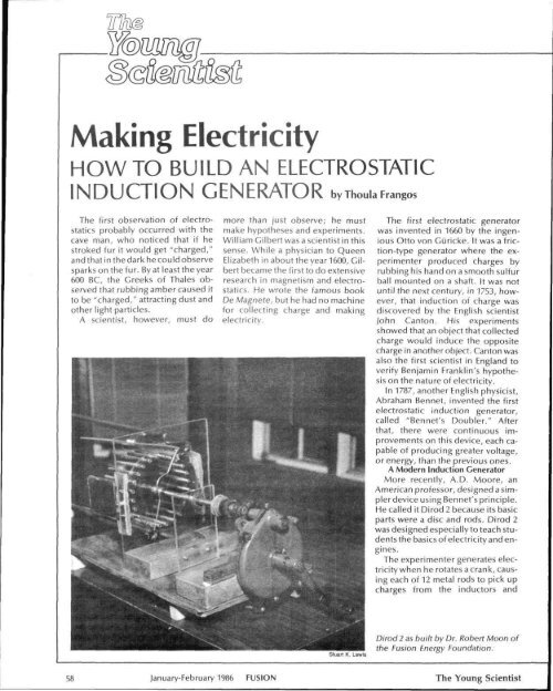
Making ElectricityHOW TO BUILD AN ELECTROSTATICINDUCTION GENERATOR by Thoula FrangosThe first observation of electrostaticsprobably occurred with thecave man, who noticed that if hestroked fur it would get "charged,"and that in the dark he could observesparks on the fur. By at least the year600 BC, the Greeks of Thales observedthat rubbing amber caused itto be "charged," attracting dust andother light particles.A scientist, however, must domore than just observe; he mustmake hypotheses and experiments.William Gilbert was a scientist in thissense. While a physician to QueenElizabeth in about the year 1600, Gilbertbecame the first to do extensiveresearch in magnetism and electrostatics.He wrote the famous bookDe Magnete, but he had no machinefor collecting charge and makingelectricity.The first electrostatic generatorwas invented in 1660 by the ingeniousOtto von Guricke. It was a friction-typegenerator where the experimenterproduced charges byrubbing his hand on a smooth sulfurball mounted on a shaft. It was notuntil the next century, in 1753, however,that induction of charge wasdiscovered by the English scientistJohn Canton. His experimentsshowed that an object that collectedcharge would induce the oppositecharge in another object. Canton wasalso the first scientist in England toverify Benjamin Franklin's hypothesison the nature of electricity.In 1787, another English physicist,Abraham Bennet, invented the firstelectrostatic induction generator,called "Bennet's Doubler." Afterthat, there were continuous improvementson this device, each capableof producing greater voltage,or energy, than the previous ones.A Modern Induction GeneratorMore recently, A.D. Moore, anAmerican professor, designed a simplerdevice using Bennet's principle.He called it Dirod 2 because its basicparts were a disc and rods. Dirod 2was designed especially to teach studentsthe basics of electricity and engines.The experimenter generates electricitywhen he rotates a crank, causingeach of 12 metal rods to pick upcharges from the inductors andStuart K. LewisDirod 2 as built by Dr. Robert Moon ofthe Fusion Energy Foundation:58 January-February 1986 FUSION The Young Scientist
transmit them to collector plates viaconductive tape, called brushes. Thevoltage of charge builds up on thecollector plates.To see how this device generateselectricity look at Figure 1. The disc,D, is made of Plexiglas, a high-gradeinsulator (an insulator is a nonconductorof electricity). The rods,numbered Rl through R12, the twocollector plates, and the two attachedinductors, are made of metal.There is a neutral wire (or chain), N,that has conducting brushes on eachend, which are now touching R12 andR6.As you can see, the conductingbrush touching R12 has a positivecharge, while the conducting brushtouching R6 has a negative charge.There are also conducting brushesattached to the collector plates thatare now touching RIO and R4.Now where does the initial chargecome from to start the build-up ofvoltage? The experimenter's handlingand touching of the plexiglassby working with it will put enoughcharge on the surface to "induce"charges on the collectors.Since unlike charges attract eachother, the minus (negative) chargeson inductor 1 will attract plus (positive)charges and cause them to appearon rod R12. The opposite occursfor inductor 2 and rod R6, wherenegative charges collect. The chargeson R12 and R6 are called inducedcharges, and these rods will now becomecharge carriers. The rods rotateand touch the conductingbrushes that stick out from the collectors.In this manner they depositmost of their charge (about threefourths)onto the collector plates,which build up charge with each rotation.It might seem as though the machinecould continue to accumulatecharge up to millions or billions ofvolts. Actually, the machine willreach only 90,000 volts, because anyadditional voltage over this limit escapesthe metal collectors, forminga corona in the air around the collectors.You can see this corona—brightspots near the conducting brushes—whenyou operate your machinein the dark.What You Will NeedTo build Dirod 2, you will needequipment that is found in a schoolmachine shop or a mechanic's shop.This is a good project, in fact, for aclass that has access to a machineshop. Here is the shop equipmentyou will need:LatheReamerDrillBandsaw or jigsawBelt sanderCenter punchFileTriangles for measuringSolderHere are the materials you willneed. You may be able to find muchof this second-hand.7 pieces of Plexiglas (V4-inch or3 /s-inch thick)1 major plate, 9" x 9"1 minor plate, 9" x 7"2 corona shields, 7" x 7"2 supports for shields, V*" x 3"1 disc, 6-inch diameter12 aluminum rods ('A-inch diameter),5 inches long2 aluminum or brass plates, 3" x4" X Va"6 feet heavy copper wire, VB" rodstock1 mechanical crank1 metal shaft1 plywood (for base), about 20"x 20"24 screws, 8-32 machine screws12 Allen screwsepoxy gluekerosene (small amount)silver conducting paint (smallamount)tracing paper or vellum for drawingBuilding Dirod 2If you have never built anything asambitious as Dirod 2, this will giveyou invaluable experience with thenature of materials and how to adaptthem to your needs. You will alsolearn how to use hand methods andsimple machine processes to completeyour project.Collectorplate 1Figure 1FRONT VIEW OF DIROD 2SHOWING DISTRIBUTIONOF CHARGES^ e negative (-) and positive(+) charges on the inductorsare picked up by the rotatingmetal rods, numbered Rlthrough R12, and depositedon the collector plates.Here is how to put Dirod 2 together:First, look at the drawings to familiarizeyourself with the device.Front and side views are shown inFigures 3 and 4, while Figure2 showshow the entire apparatus comes together.Before you start building, itis a good idea to make full size drawingsof Figures 3 and 4 on heavy tracingpaper or vellum; it will help toavoid mistakes.The Main PartsA wood base supports both thegenerator and crank that operates it.The two main vertical parts attachedto the base are Plexiglas plates; theminor one supports the shaft thatconnects the disc with the crank, andthe major one supports the disc itself,corona shields, and collectorplates. The collector plates in turnThe Young Scientist FUSION January-February 1986 59