ION MODULATED ORGANIC TRANSISTORS - Doria
ION MODULATED ORGANIC TRANSISTORS - Doria
ION MODULATED ORGANIC TRANSISTORS - Doria
- No tags were found...

Create successful ePaper yourself
Turn your PDF publications into a flip-book with our unique Google optimized e-Paper software.
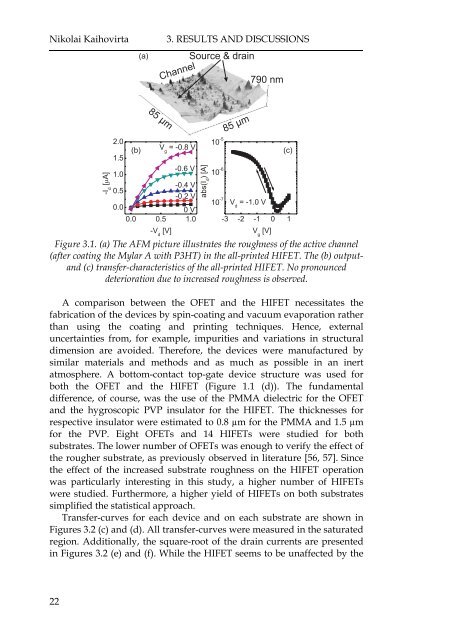
Nikolai Kaihovirta(a)3. RESULTS AND DISCUSS<strong>ION</strong>SChannelSource & drain790 nm-I d[A]85 µm2.01.5(b) V g=-0.8V1.0-0.6 V0.5-0.4 V-0.2 V0.00V0.0 0.5 1.0-V d[V]abs(I d)[A]10 -510 -610 -785 µmV d=-1.0V-3 -2 -1 0 1V g[V]Figure 3.1. (a) The AFM picture illustrates the roughness of the active channel(after coating the Mylar A with P3HT) in the all-printed HIFET. The (b) outputand(c) transfer-characteristics of the all-printed HIFET. No pronounceddeterioration due to increased roughness is observed.(c)A comparison between the OFET and the HIFET necessitates thefabrication of the devices by spin-coating and vacuum evaporation ratherthan using the coating and printing techniques. Hence, externaluncertainties from, for example, impurities and variations in structuraldimension are avoided. Therefore, the devices were manufactured bysimilar materials and methods and as much as possible in an inertatmosphere. A bottom-contact top-gate device structure was used forboth the OFET and the HIFET (Figure 1.1 (d)). The fundamentaldifference, of course, was the use of the PMMA dielectric for the OFETand the hygroscopic PVP insulator for the HIFET. The thicknesses forrespective insulator were estimated to 0.8 µm for the PMMA and 1.5 µmfor the PVP. Eight OFETs and 14 HIFETs were studied for bothsubstrates. The lower number of OFETs was enough to verify the effect ofthe rougher substrate, as previously observed in literature [56, 57]. Sincethe effect of the increased substrate roughness on the HIFET operationwas particularly interesting in this study, a higher number of HIFETswere studied. Furthermore, a higher yield of HIFETs on both substratessimplified the statistical approach.Transfer-curves for each device and on each substrate are shown inFigures 3.2 (c) and (d). All transfer-curves were measured in the saturatedregion. Additionally, the square-root of the drain currents are presentedin Figures 3.2 (e) and (f). While the HIFET seems to be unaffected by the22