September/October 2000 NCJ
September/October 2000 NCJ
September/October 2000 NCJ

Create successful ePaper yourself
Turn your PDF publications into a flip-book with our unique Google optimized e-Paper software.
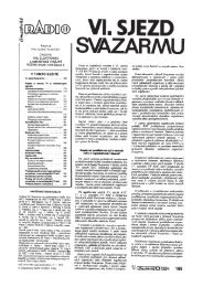
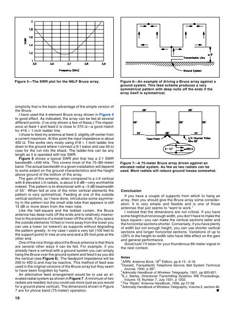
Figure 5—The SWR plot for the N6LF Bruce array.Figure 6—An example of driving a Bruce array against aground system. This feed scheme produces a verysymmetrical pattern with deep nulls off the ends if thearray itself is symmetrical.simplicity that is the basic advantage of the simple version ofthe Bruce.I have used the 4-element Bruce array shown in Figure 4to good effect. As indicated, the array can be fed at severaldifferent points. (I’ve only shown a few of these.) The impedanceat feed-1 and feed-2 is close to 370 Ω—a good matchfor #16 × 1-inch ladder line.I chose to feed my antenna at feed-3, slightly off-center froma current maximum. At this point the input impedance is about450 Ω. This works very nicely using #18 × 1-inch ladder linedown to the ground where I connect a 9:1 balun and use 50-Ωcoax for the run into the shack. The ladder-line can be anylength as it is operated with low SWR.Figure 5 shows a typical SWR plot that has a 2:1 SWRbandwidth >400 kHz. This covers most of the 75-/80-meterband. The actual bandwidth in a given installation will dependto some extent on the ground characteristics and the heightabove ground of the bottom of the array.The gain of this antenna, when compared to a λ/4 verticalwith 8 elevated λ/4 radials, is about 4.6 dB—very worthwhileindeed. The pattern is bi-directional with a –3 dB beamwidthof 55°. When fed at one of the inner vertical elements thepattern is very symmetrical. Feeding at one of the outsidevertical sections, as I have done, introduces some asymmetryin the pattern but the small side lobe that appears is still15 dB or more down from the main lobe.Like the half-square and the bobtail curtain, the Bruceantenna has deep nulls off the ends and is relatively insensitiveto the presence of a metal tower off the ends. If you spacethe outside elements 10 feet or more away from the tower youcan use a tower (or towers!) as supports without degradingthe pattern greatly. In my case I used a very tall (100 feet tothe support point) fir tree at one end and a 95-foot pole at theother end.One of the nice things about the Bruce antenna is that thereare several other ways it can be fed. For example, if youalready have a vertical with a ground system you can simplyhang the Bruce over the ground system and feed it as you didthe vertical (see Figure 6). The feedpoint impedance will be200 to 400 Ω and may be reactive. This method of feed wasused in the original versions of the Bruce array but they seemto have been forgotten by hams.An alternative feed arrangement would be to use an elevatedradial system as shown in Figure 7. A minimum of tworadials are needed, but you could use more (just as you wouldfor a ground-plane vertical). The dimensions shown in Figure7 are for phone band (75-meter) operation.Figure 7—A 75-meter Bruce array driven against anelevated radial system. As few as two radials can beused. More radials will reduce ground losses somewhat.ConclusionIf you have a couple of supports from which to hang anarray, then you should give the Bruce array some consideration.It is very simple and flexible and is one of thoseantennas that just seems to “want to work.”I noticed that the dimensions are not critical. If you havesome height but not enough width, you don’t have to make thebays square—you can make the vertical sections taller andthe horizontal sections shorter. Conversely, if you have plentyof width but not enough height, you can use shorter verticalsections and longer horizontal sections. Variations of up to±20% in the height-to-width ratio have little effect on the gainand general performance.Good luck! I’ll listen for your thunderous 80-meter signal inthe next contest.Notes1 ARRL Antenna Book, 18 th Edition, pp 6-13 - 6-16.2 Oswald, Transatlantic Telephone Service, Bell System TechnicalJournal, 1930, p 287.3 Admiralty Handbook of Wireless Telegraphy, 1931, pp 820-821.4 E.J. Sterba, Directional Transmitting Systems, IRE Proceedings,Volume 19, Number 7, July 1931, p 1202.5 The “Radio” Antenna Handbook, 1936, pp 57-58.6 Admiralty Handbook of Wireless Telegraphy, Volume 2, section 46.■16