SV-210_211_213_215_2.. - Page de test
SV-210_211_213_215_2.. - Page de test
SV-210_211_213_215_2.. - Page de test

Create successful ePaper yourself
Turn your PDF publications into a flip-book with our unique Google optimized e-Paper software.
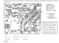
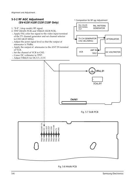
Alignment and Adjustment5-3-2 RF AGC Adjustment(<strong>SV</strong>-415F/410F/<strong>215</strong>F/<strong>210</strong>F Only)1. ÒE-EÓ, (stop mo<strong>de</strong>), RF signal.<strong>2.</strong> TP07 (MAIN PCB) and VR4L01 (SUB PCB),-. Apply PAL color bar signal to the vi<strong>de</strong>o input terminalof the TV channel generator and set channel selectorto CH2 (48.25 MHz).-. Adjust the point signal level so that the output ofattenuator is 70dBu.-. Apply the output of attenuator to the ANT IN terminalof VCR.-. Set the chaneel of VCR to CH<strong>2.</strong>-. Conec DC voltmeter to TP07.-. Adjust VR4L01 for DC3.5 ± 0.1V.* Composition for RF agc AdjustmentPAL COLORBAR SIGNALOUTTV CH GENERATORCH2 (48.25MHz)VCRPAL PATTERNGENERATORANT INTP07ATTENUATORDC VOLTMETERFig. 5-7 SUB PCBTP08TP07TP06TP05TP04TP03TP02TP01SCART CTLAGCV.OUTA.OUTV.ENVH'D SWCTLGNDFig. 5-8 MAIN PCB5-6 Samsung Electronics