INFORMATION BULLETIN
INFORMATION BULLETIN
INFORMATION BULLETIN

Create successful ePaper yourself
Turn your PDF publications into a flip-book with our unique Google optimized e-Paper software.
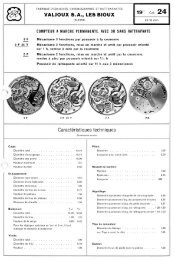
NO. 575<strong>INFORMATION</strong><strong>BULLETIN</strong>Published by Longines-Wittnauer Watch. Co., Inc., New York 36, N. Y, U.S.ARESERVE POWER INDICATORLeCOULTRE CALIBER 481There are numerous devices for recordingtheamount of ma,inspring power stored in the barrel.They were employed very early in the marinechronometer and later in the accurate, railroadtypepocket timepiece. Now they perform a usefulservice in the self-winding watch.The principleof every such device is that whenthe mainspring is wound through the ratchet,manually or automatically, a special train of gearsconnected to the ratchet moves an indicator acrossa graduated dial showing the extent of this winding.The barrel teeth, too, are connected to thesame train so that when it utilizes the mainspring'spower, this same train is made to reverse itself andthe indicator hand moves in the opposite direction./~ G~~t IFEMost of these types of reserve-power indicatingdevices are designed so that the ratchet moves theindicator in one direction, while the barrel, goingalso in the same direction as the ratchet, influencesthe indicator in the opposite direction. Thisis done most often by introducingan additionalgear between the ratchet and the indicator train.These units are composed of a system known asdifferential gearing (a series of gears connected todifferent power sources, permitting the differentspeeds of each source to influence the same axle,such as the post upon which an indicator handmight be fitted). An automobile uses a similarsystem so that each rear wheel may be turned atdifferent speeds as when making a sharp turn ormaneuvering for parking.In figure 1 is the system used by the LeCoultreCalibre 481. This has an ingenious yet simple dif.ferential device to show the power stored by theFigure I-Exploded, schematic view of the differential forreserve power indicator such as used with the LeCoultreCal.481.self-winding or the manually wound mainspring.This view shows the scheme of the differential inexploded section. The differential axle F (alsocalled a satellite spindle) pivots freely betweenthe upper and lower plates of the movement.The upper differentialgear H and the lower gearE are free to turn on shoulders of the differentialaxle. Both wheels Hand E have dual sets of radialand crown teeth. The differential pinion G ismounted on the shoulder of the cross-arbor GAand is free to turn on this arbor. The top pivot ofF, with its notch, extends up through the dialplate, and the driving pinion] snaps onto thispivot like a cannon pinion.
)'0E/the comparatively motionless barrel, the differentialpinion G will have to roll around it as shownat F. The cross-arbor of pinion G thus causes thedifferential axle F to turn counterclockwise. Thedriving pinion J, clutch-tight on the protrudingpivot of axle F, is also carried counterclockwise.This causcs the intermediate wheel K to turnclockwise and its pinion thus turns the indicatordisk in the counterclockwise direction so that thenumbers on this disk, showing the amount of runningtime in the barrel's power, grow progressivelygreater. Notice that the portion of this diskfrom 10 to 0 is shaded, usually in red. This is tonotify the wearer that there is not much actionremaining in the barrel.Figure 2-Looking at the differential as it is geared to thebarrel and the ratchet wheel from the dial-up position.Parts K, L, M, ,",' are fitted to this unit above the dial platebut under the regular dial.Figure 2 shows the differentialas assemhled to thewinding mechanism, in the dial-up position. A isthe mainspring barrel whose teeth are enmeshedwith the satellite wheel H of the differential. Theratchet wheel C, wound either manually throughthe crown wheel B or through the self-windingtrain, is engaged with the reversing pinion Dwhich serves to change the direction of the wheelE when the ratchet is the motivating factor. Thedifferential pinion G is shown mounted on itscross arbor and enmeshed with the crown teethof both the lower and upper satellite wheels Hand E. The driving pinion]is shown here snappedinto place under the" regular dial; this drives theintermediate wheel K, and the pinion L is enmeshedwith the dial-disk M. The dial-disk iskept in place under the dial by its dial washerN. The dial-disk M has teeth cut only partiallyaround its circumference. Its uncut portions serveto indicate the outer limits of the winding range.Figure 3 shows the action when the ratchet wheel,wound manually or by the automatic train, windsfaster than the barrel can unwind.Here, theratchet C, moving counterclockwise (in thedial-up position), rotates the reversing pinion Din the clockwise direction, which in turn movesthe satellite wheel E in the counterclockwisedirection.The differentialpinion G is turned downwardin the direction of the arrow by the crownteeth of wheel E. Since this pinion G is alsogeared to the crown teeth of wheel H and thisupper wheel cannot move because it is geared toFigure 3-Showing the action of the indicator mechanismwhen the winding of the ratchet takes place. Follow theaction starting from the ratchet C, and continue upthrough the reverser 0, the lower satellite wheel E, thedifferential pinion G, the axle F, the (cannon) drivingpinion J, the intermediate wheel K and the dial-disk M.The upper satellite wheel H and the barrel A are consideredas motionless in this sequence.The schematic drawingsequence when the windingthe barrel and mainspringwound. The barrel A is movingin Figure 4 shows theis not in action, butare now being un.in the counterclockwisedirection. The barrel teeth cause thesatellite wheel H to turn clockwise, and its crownteeth, engaged with the differential pinion G,cause this to turn upwards or counterclockwise.Because the lower satellite wheel E cannot movewith the pinion G as it is connected to the reverserpinion D and the ratchet C, the differentialpinionG must therefore roll around the wheel E, carriedalong by the upper satellite wheel H and turningwith it.
place, either manually or through the automaticwinding train, regardless o( the slip-spring. Thisis because axle F J influenced by the tight pinion,exerts additional force on the barrel teeth throughthe upper satellite wheel H.Figure 4- This figure shows the action and direction of thedifferential parts when the winding is motionless but thebarrel and mainspring are unwinding, Follow this sequencefrom the barrel A through the upper satellitewheel H to the differential pinion G, the differential axleF, the driving pinion ], the intermediate wheel and pinionK and finally to the dial-disk M, Notice that in this figure,he last of the teeth of ' the disk M are against the pinionL of the intermediate wheel, Any further action of the unwindingwill cause the axle F to slip-clutch with the drivingpinion],Since the differential pinion G is attached to thecross-arbor which is part of the differential axleF, the axle F turns in the clockwise direction asshown by the arrow. The driving pinion] turnswith this axle and moves the intermediateK and its pini:>n in the counterclockwisewheeldirection.The pinion L thus turns the dial-disk in theclockwise direction so that the numbers, shownthroughthe regular dial's aperture, become regressivelysmaller.In this illustration, the dial-disk M is shown enmeshedwith the pinion L of the intermediatewheel K, so that the dial-disk'steeth are lockedat the point where the rim of this disk ceases tohave teeth. The aperture will then show 0, indicatingthat the watch should either be worn orwound manually.As with other watches using a "cannon-pinion"type of driving pinion like pinion], should itsclam-notch require tightening, this should be donein moderation, introducing only enough friCtionto permit it to be carried around and still carryboth the intermediate wheel and pinion and thedial-disk. Should the pinion] be made too tighton the axle F, this may cause rebounding of thebalance when the maximum winding has takenWhen oiling this device, use a heavier oil, suchas a clock oil, at the pivots and shoulders of theaxle F and at the bearing of G, and apply just alittle to the crown teeth of the upper and lowersatellite wheels Hand E. Do not oil the snap-onpart of the axle F. However, place a small amountof clock oil at the bearing hole of the reverserpinion D. Assemble as in these figures; no specialposition is required when positioning the disk M;merely wind this manually until you can feel theslip-spring take action. The disk's aperture willthen read 40.RESERVE POWER INDICA TORSReserve Power Indicators for self-winding watchesare typical of the worthwhile innovations in watchdesign which have been pioneered by LeCoultre.The first automatic watch with reserve power indicatorwas made by LeCoultre and rapidly copiedby others. You, as a watchmaker familiar withLeCoultre movements and mechanical designs,will appreciate both the fine quality of LeCoultreworkmanship and the practical worth of the manyLeCoultre innovations.You will be interested to know that LeCoultre isone of the few watchmakers who successfully madethe transition from hand to machine manufacture.The firm was established in 1833, and early handmadeLeCoultre watches, of exquisite workmanship,are treasured historic items in ma~y collections.Antoine LeCoultre, founder of the firm, wasone of the great geniuses at watchmaking. Anearly achievement was the generation of a pivotfrom a single piece of steel for which accomplishmentLeCoultre was awarded a prize at the BritishInternational Exposition of 1851. In that sameyear, LeCoultre began the manufacture of stemwindingwatches years ahead of the field.Among the sensational items now in regular productionby LeCoultre are the most complicatedwatch, the thinnest pocket watch and the smallestwrist watches in all the world. The latter, aboutthe size of a match head, has 85 perfectly formedparts and keeps remarkably good time.
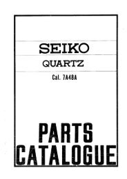
CAL. 12" -481BASE CAL. 12" -476v~@f205210125 166 160/1182 195 245 255 260 301- '" 0 0 () "'~~~-c ~ ~401 4.07 410 415 420 423 434 435 440 443 445@--L-T&-,.--.0-~0 :$ J."AIT~r~7050 () '" c450 453 498 710 721 723 730 734/1 736t7 o\\W...i A, W.'i771 1341 1428 1448 14721472/5I ~ \1 'Ill 'ij' W - " ~u ~Ii '- -if Hijl'Ii 11g -IfIji 5440 U714 738/1 5110 5125 512q 5166 54:>0 5434 5443 5445 5738/1 575051131.51132.5114451341.51428.51448.51472125 Pollet cock 423 Crown wheel core 771 Mainspring wIth broke spring 51132 Screw for oscIllating weight lower166 CasIng clomp 434 ClIckIng spring 775 Broke spring bridge180/1 Barrel complete with mainspring 435 .Yoke 1144 Bonking stop 51144 Bonking stop screw182 Barrel and cover 440 Yoke sprIng 1341 OscIllatIng weIght bearing 51341 Oscillating weight bearing screw195 Barrel arbor 443 5ettlng lever 1428 Stop click 51428 Stop click screw20S Center wheel an.d. pinion. drilled, 445 SettIng lever sprIng 1448 Stop click spring S1448 Stop cilck spring screwwIth cannon plnlo~ 450 5ettln!! wheel 1472 BankIng stop spring (weight) 51472 Banking stop spring screw210227ThIrd wheel and pInion5weep second wheel and pinion453498Addlt!onal settIngFrIctIon washer.wheel 1472/51488BonkIng stop springPawl winding wheel(bridge)605 Jewel for thl.'d wheel. upper245 Cannon pinion with clam-notch 705 E5cape wheel and pInIon. 606 Jewel for thIrd wheel. lowerfor sweep second (mention heiphl) 710 Jewelled pollet fork and stoff ~:~~ ~r;1~e screw 612 Jewel for sweep secQnd wheel..255 Hour wheel for sweep second 714 Pallet staff a e cock screw upper(mention height) 720 Balance with roller. pivoted (men- 5126 Center wheel cock screw 615-616 Jewel for escape wheel. upper anj260 Minute ..heel tion 13 of jewel hole) 5166 CaSIng-clamp screw lower301 Regulator for flat hairspring 721 Balance with flat hairspring. re- ~4~0 ~rown whee! screw 620-621 Jewel for pallet slaff, upper and401 Winding stem (mention 13 of gulcted (mention 13 of jewel hole) 4 4 Ilckl'!Q spring screw lowerIhreading) 723 Balance stoff, pivoted 5443 SettIng lever screw 1641 Jewel for osclllatlngwelf!ht. upper407 Clutch wheel 730 Roller 5440- Yoke spring ond settIng lever spring 1642 Jewel for oscliiallng welghl, lower410 Winding pinion 73411 Flat hairspring, regulated. trian- ~j 38 4511 T screw, d 1628 Jewel for pawl winding wheel,414 Crown wheel seat gular stud rlangu ar stu screw upper415 Ratchet wheel 736 Collet for flat hairspring 5750 D,al screw.. 1679 Bushing for pawl .Ninding wheel,420 Crown wheel 738/1 Triangular stud for flat hairspring 51131 Scrbewd for 05clllatln{) weIght upper lowerrI ge0 ey-T-$T498 9510 9512 9540 954195429543954559545!..498 Friction washer9510 Driving runner for indicator whee'9512 Indicator wheel954;) Upper satellite wheel9;41 Lower sate/lite wheel9542 Satellite pinion9543 Satellite spindle9545 Intermediate connecting wheel forupper satellite wheel59545 Screw for intermediate conneclingwheel for upper satellite wheel