technical guide
technical guide
technical guide

You also want an ePaper? Increase the reach of your titles
YUMPU automatically turns print PDFs into web optimized ePapers that Google loves.
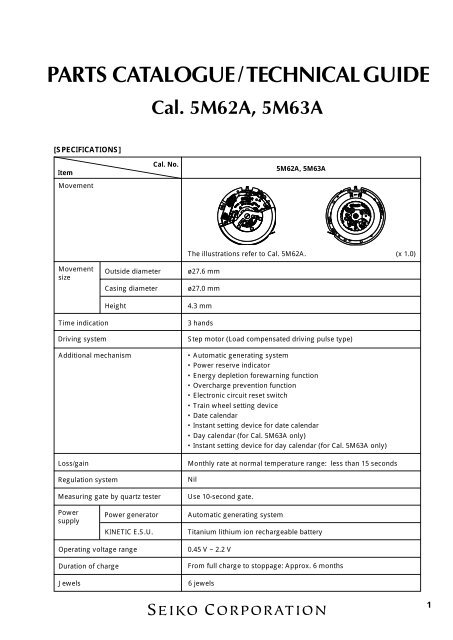
PARTS CATALOGUE / TECHNICAL GUIDECal. 5M62A, 5M63A[SPECIFICATIONS]ItemMovementCal. No.5M62A, 5M63AThe illustrations refer to Cal. 5M62A.(x 1.0)MovementsizeOutside diameterCasing diameterHeightø27.6 mmø27.0 mm4.3 mmTime indicationDriving systemAdditional mechanismLoss/gainRegulation systemMeasuring gate by quartz tester3 handsStep motor (Load compensated driving pulse type)• Automatic generating system• Power reserve indicator• Energy depletion forewarning function• Overcharge prevention function• Electronic circuit reset switch• Train wheel setting device• Date calendar• Instant setting device for date calendar• Day calendar (for Cal. 5M63A only)• Instant setting device for day calendar (for Cal. 5M63A only)Monthly rate at normal temperature range: less than 15 secondsNilUse 10-second gate.PowersupplyPower generatorKINETIC E.S.U.Automatic generating systemTitanium lithium ion rechargeable batteryOperating voltage rangeDuration of chargeJewels0.45 V ~ 2.2 VFrom full charge to stoppage: Approx. 6 months6 jewels1
PARTS CATALOGUECal. 5M62A, 5M63ADisassembling procedures Figs. : 1 → 61Reassembling procedures Figs. : 61 → 1Lubricating: Types of oil Oil quantityMoebius ANormal quantityMoebius FSEIKO Watch Oil S-6Silicone oil 500,000 c.s.1 Case back9 Hour, minute andsecond hands10 Dial2 Case backgasket4 4281 500Contact pointspring (*)* The contact point springis not assembled inmodels with screw-locktype crown.5 Movement6 Button springclip3 Winding stem11 Holding ring for dial12 0491 589Dial washer13 0963 781Snap for day star withdial disk(Only for Cal. 5M63A)14 Day star with dial disk(Only for Cal. 5M63A)15 0989 660Intermediate wheel forday correction(Only for Cal. 5M63A)16 0022 247Date dial guard screw17 0808 660Date dial guard8 Button spring18 Date dial7 Button0022 247• Date dial guard screw (3 pcs.)• Rechargeable battery clamp screw(2 pcs.)• Circuit block cover screw (2 pcs.)• Oscillating weight bridge screw(2 pcs.)• Coil block screw(1 pc.)• Train wheel bridge screw (1 pc.)0022 490• Oscillating weight screw(1 pc.)19 0737 670Day-date corrector wheel20 0962 670Intermediate wheel forcalendar corrector21 0810 660Date jumper22 0816 670Date driving wheel23 0271 670Hour wheel➡ Pleasesee the remarks on the following pages.Lubricating of some parts is shown in “II. REMARKS ON DISASSEMBLING AND REASSEMBLING”.2
PARTS CATALOGUECal. 5M62A, 5M63A24 0022 490Oscillating weight screw25 0500 663Oscillating weight26 1002 662Oscillating weight wheel27 0022 247Rechargeable battery clamp screw28 4225 519Rechargeable battery clamp29 4216 519Insulator for rechargeable battery30 3023 44ZRechargeable battery unit31 0022 247Circuit block cover screw32 4457 760Circuit block cover33 4000 732Circuit block34 0022 247Oscillating weight bridge screw35 4459 500Conductive plate36 0198 662Oscillating weight bridge37 4002 514Generating coil block38 1002 660Intermediate wheel for generating rotor39 4146 518Generating rotor40 4239 519Generating stator41 0022 247Coil block screw42 4002 516Coil block➡ Pleasesee the remarks on the following pages.Lubricating of some parts is shown in “II. REMARKS ON DISASSEMBLING AND REASSEMBLING”.3
PARTS CATALOGUECal. 5M62A, 5M63A43 0022 247Train wheel bridge screw44 0125 661Train wheel bridge45 0391 660Train wheel setting lever46 4271 515Rechargeable batteryconnection (+)47 0241 670Fourth wheel and pinion48 0231 530Third wheel and pinion49 0701 670Fifth wheel and pinion50 4146 531Step rotor51 0261 670Minute wheel52 0281 670Setting wheel53 4450 730Switch lever54 0384 661Yoke55 0383 662Setting lever56 0397 660Lever for unlocking stem(Only for one-piece case type)57 4239 518Rotor stator58 Winding stem59 0282 672Clutch wheel60 0221 676Center wheel and pinion61 0100 669 (For standard case type)0100 659 (For one-piece case type)Main plate➡ Pleasesee the remarks on the following pages.Lubricating of some parts is shown in “II. REMARKS ON DISASSEMBLING AND REASSEMBLING”.4
PARTS CATALOGUECal. 5M62A, 5M63ARemarks:4 Contact point spring 4281 500The contact point spring is not assembled in models with screw-lock type crown.11 Holding ring for dial 0866 636The type of holding ring for dial is determined based on the design of cases.Check the case number and refer to “SEIKO Casing Parts Catalogue” to choose a corresponding holdingring for dial.14 Day star with dial disk (Only for Cal. 5M63A)Part codeLanguagePosition ofcrownPosition ofcalendar frameColor of figureColor ofbackground0150 661English ↔ Spanish3 o’clock3 o’clockBlackWhite0150 663 English ↔ Spanish 3 o’clock 3 o’clock GoldBlack0150 659 English ↔ Spanish 3 o’clock 3 o’clock WhiteBlackThe type of day star with dial disk is determined based on the design of cases.Check the number printed on the day star with dial disk to choose a corresponding one.18 Date dialCal. No.Part codePosition ofcrownPosition ofcalendar frameColor of figureColor ofbackground5M62A0878 7293 o’clock3 o’clockBlackWhite0878 7303 o’clock3 o’clockWhiteBlack0878 7313 o’clock3 o’clockBlackGold0878 7323 o’clock3 o’clockGoldBlack0878 8763 o’clock4 o’clockBlackWhite0878 8773 o’clock4 o’clockWhiteBlack5M63A0878 6723 o’clock3 o’clockWhiteBlack0878 6733 o’clock3 o’clockGoldBlack0878 6753 o’clock3 o’clockBlackWhiteThe type of date dial is determined based on the design of cases.Check the case number and refer to “SEIKO Casing Parts Catalogue” to choose a corresponding datedial.5
PARTS CATALOGUECal. 5M62A, 5M63A56 Lever for unlocking stem 0397 660The lever for unlocking stem is used only with one-piece case type models.58 Winding stem 0351 653The type of winding stem is determined based on the design of cases.Check the case number and refer to “SEIKO Casing Parts Catalogue” to choose a correspondingwinding stem.TECHNICAL GUIDECal. 5M62A, 5M63A• The explanation here is only for the particular points of Cal. 5M62A and 5M63A.• For the repairing, checking and measuring procedures, refer to the “TECHNICAL GUIDE, GENERALINSTRUCTIONS”.I. STRUCTURE OF THE CIRCUIT BLOCKCrystal unitCoil output terminalInput terminal (–)C-MOS-ICInput terminal (+)Automatic generatinginput terminalII.REMARKS ON DISASSEMBLING AND REASSEMBLINGFor disassembling and reassembling, be sure to use the universal movement holder.4 Contact point springThe contact point spring has three hookingportions bent downward. It is fixed by insertingthe hooking portion “A” into a gap between themain plate and holding ring for dial and inserting“B” and “C” into a gap between the holding ringfor dial and case. “B” “A” “C”* Before disassembling or assembling the contact point spring, be sure to remove the winding stem.6
TECHNICAL GUIDECal. 5M62A, 5M63A• How to removeInsert the tip of tweezers into the gaps between the hooking portions “A”, “B” and “C” of the contactpoint spring and holding ring for dial, and pry up the contact point spring slowly to remove it.• How to install1) Push the hooking portion “A” in thedirection of the arrow in the illustration atright to insert it into a gap between themain plate and holding ring for dial.Hooking portion “A”2) Insert the hooking portions “B” and “C”into a gap between the holding ring fordial and case.In doing so, the installation will be mademore easily by pushing down the contactpoint spring while slightly lifting it up sothat the tips of the hooking portions “B”and “C” are tilted toward the holding ringfor dial.Note: When removing or installing the contactpoint spring, take utmost care not todeform its shape.CaseContact point springHolding ring for dial9 HandsPlace the movement directly on the riveting plate shown in the illustration with the oscillating weightdown, so that the oscillating weight screw is not damaged. Then, press in the hands.24 Oscillating weight screwTighten the oscillating weight screw firmly,applying more force than usual.Oscillating weight screw7
TECHNICAL GUIDECal. 5M62A, 5M63A30 Rechargeable battery unitThough the rechargeable battery unit for Cal. 5M6 Series is of a completely different type from thecapacitor unit for Cal. 5M4 Series, they have a close resemblance in shape. They can be discriminatedby the shapes of their minus lead terminals as illustrated below. When repairing the rechargeablebattery unit, check the shape of its minus lead terminal to make sure you are using a rechargeablebattery unit properly.Minus lead terminalMinus lead terminalCurrent typeOld type[ Rechargeable battery unit for Cal. 5M6 Series ] [ Capacitor unit for Cal. 5M4 Series ]• How to removeInsert the tip of tweezers into the “C” portiongap in the illustration at right, and pry up therechargeable battery unit to remove it.“A” portion“B” portion• How to installSet the “A” portion of the minus lead terminalto the hole of the main plate, and push the “B”portion down vertically so that therechargeable battery unit is well seated inposition.Rechargeablebattery plusterminalNote: Take utmost care not to short-circuit the(+) and (–) terminals, as this will deterioratethe battery unit.Main plate“C” portionMinus lead terminal32 Circuit block coverCircuit block cover for after-sales servicing usehas no such marks printed on it as calibre numberand numeral indicating hand installation height.8
TECHNICAL GUIDECal. 5M62A, 5M63A33 Circuit blockThe circuit block for Cal. 5M6 Series and that for Cal. 5M4 Series have a close resemblance in shape.They can be discriminated in the point that the circuit block for Cal. 5M6 Series has no diode elementunlike that for Cal. 5M4 Series. When repairing the circuit block, check that it has no diode element tomake sure you are using the proper one.Having no diode elementDiode element[ Circuit block for Cal. 5M6 Series ] [ Circuit block for Cal. 5M4 Series ]34 Oscillating weight bridge screw36 Oscillating weight bridge· Before tightening the oscillating weight bridgescrew, check that the upper pivot of thegenerating rotor is inserted properly into thepivot jewel.· Be sure to lubricate the upper and lower pivotsof generating rotor and intermediate wheel forgenerating rotor with the proper oil in thequantity specified in the illustration.Generating rotorIntermediate wheel forgenerating rotor· Lubricate the ball-bearing of the oscillatingweight bridge as shown in the illustration atright.37 Generating coil blockThe generating coil block for Cal. 5M6 Series and that for Cal. 5M4 Series have a close resemblance inshape. They can be discriminated by the size of the pattern on the lead terminal. If the generating coilblock for Cal. 5M4 Series is assembled by mistake, no electricity will be generated. When repairing thegenerating coil block, check the size of the pattern on the lead terminal to make sure you are using theproper one.Smaller patternLarger pattern[ Generating coil block for Cal. 5M6 Series ] [ Generating coil block for Cal. 5M4 Series ]Lubricating:: Moebius A9
TECHNICAL GUIDECal. 5M62A, 5M63A38 Intermediate wheel for generating rotor• LubricatingRefer to the illustration at right.Note: Be sure to observe the position, type of oiland quantity of the lubrication specifiedin the illustration.47 Fourth wheel and pinion48 Third wheel and pinion49 Fifth wheel and pinion50 Step rotor51 Minute wheel52 Setting wheel60 Center wheel and pinion• Setting position and lubricatingRefer to the illustrations below for the setting position and lubrication of the respective wheels.Step rotorStep rotorFifth wheeland pinionFourth wheeland pinionThird wheeland pinionFifth wheeland pinionSetting wheelThird wheeland pinionMinute wheelFourth wheeland pinionCenter wheeland pinionNote: Be sure to observe the position, type of oiland quantity of lubrication specified in theillustration.Minute wheelSetting wheel10Lubricating: : Moebius A : Moebius F
TECHNICAL GUIDECal. 5M62A, 5M63A45 Train wheel setting lever53 Switch leverTrain wheel setting lever54 YokeSetting lever55 Setting lever56 Lever for unlocking stem• Setting position and lubricatingRefer to the illustration at right.YokeSwitch leverLever for unlocking stem(Used only with one-piece case type models)III.VALUE CHECKING AND ADJUSTMENTThe procedures for value checking and adjustment explained here pertain to both Cal. 5M62A and5M63A.● Coil block resistance1.7 KΩ ~ 2.1 KΩ● Generating coil block resistance280 Ω ~ 380 Ω● Current consumptionFor the whole movement :For the circuit block alone :Less than 0.80 µA (with 1.55 V supplied from a battery)Less than 0.20 µA (with 1.55 V supplied from a battery)How to measure the current consumption for the whole movement1. Make the movement ready for measurement.1) Follow the disassembling procedureillustrated in this manual until you removethe rechargeable battery unit.Lubricating: : Moebius A : SEIKO Watch Oil S-611
TECHNICAL GUIDECal. 5M62A, 5M63A2) Temporarily tighten the screw “A” in theillustration, taking care not to tighten itexcessively.3) Install the oscillating weight wheel andoscillating weight and then tighten theoscillating weight screw.Screw “A”2. Apply the minus terminal to “a” portion of theinput terminal (–) in the illustration and plusterminal to the circuit block cover, respectively.Circuit block cover“a” portion3. For a few seconds after the probes of the testerare applied to the movement, the IC is in thequick start mode, and current consumptioncannot be measured properly. To switch the ICfrom the quick start to the normal handmovement mode, move the oscillating weightfrom side to side continuously for more thanthree seconds with the tester connected to themovement. The IC will detect the electricitygeneration and will be switched to the normalhand movement mode.Note: When moving the oscillating weightfrom side to side, take care lest theminus terminal of the tester touches theoscillating weight.4. After checking that the IC has been switched to the normal hand movement mode and a stablemeasurement can be obtained, read the measurement.If the measurement value remains high or unstable, repeat step “3” above.Notes:* Light may increase the current consumption, resulting in an inaccurate measurement. If the currentconsumption exceeds the standard value, protect the movement from light with a black cloth or thelike, and make a measurement again.* When the current consumption for the whole movement exceeds the standard value while the currentconsumption for the circuit block alone is within the standard value range, a driving pulse may begenerated to compensate for the heavy load applied on the gear train, etc. In that case, overhaul andclean the movement parts, and then, measure the current consumption for the whole movement again.12
TECHNICAL GUIDECal. 5M62A, 5M63AHow to measure the current consumption for the circuit block alone1. Connect the tester to the circuit block as shown in the illustration.“A” portion2. With the tester connected to the circuit block, short-circuit “A” portion in the illustration and the inputterminal (–) with conductive tweezers or the like for more than 3 seconds. The IC will be switched fromthe quick start to the normal hand movement mode.3. Checking that a stable measurement is obtained, read the current consumption.If the measurement value remains high or unstable, repeat step “2” above.Note: The current consumption measurement for the circuit block alone is particularly susceptible tolight, and a value higher than the actual measurement may be obtained if the circuit block isexposed to light. Protect the circuit from light with a black cloth or the like after following step “2”above, and then, measure the current consumption.● Checking the automatic generating system1. Apply the probes of the tester as shown in theillustration, and measure the voltage of therechargeable battery. The obtained voltage iscalled the “initial voltage”.Notes:* When applying the minus probe of the testerto the rechargeable battery, take care not toshort-circuit the lead terminal (–) and therechargeable battery clamp.* If a short-circuit has occurred, leave the watchuntouched for more than 10 minutes, andmeasure the voltage again, checking that astable measurement is obtained.2. Close the case back tentatively, and swing thewatch from side to side 200 times at a rate of 2to 3 swings a second, making an arc ofapproximately 20 cm.13
TECHNICAL GUIDECal. 5M62A, 5M63A3. Within 3 minutes after swinging the watch, measure the voltage of the rechargeable battery in thesame manner as in step “1” above.4. If the voltage obtained has increased more than 0.06 V from the initial voltage assuming that the initialvoltage is within the range between 0.5 V and 1.0 V, the automatic generating system is operatingnormally.[ For your information ]1. Number of swings and power reserve· When the watch stops completely, swinging it approximately 250 times at a rate of 2 to 3 times asecond will start the second hand moving at normal one-second intervals instead of two-secondintervals, indicating that approximately one day of power has been reserved.If the second hand still moves at two-second intervals after 250 swings, swing the watch further untilit moves at one-second intervals.· While the second hand is moving at one-second intervals, 200 to 250 swings will reserve up to oneday of power.2. Power reserve indication and duration of charge until the watch stops operating· Cal. 5M62A and 5M63A are equipped with a power reserve indicator. The current power reserve canbe checked using the second hand at the press of the power reserve indicator button.Quick movement of the second hand when thepower reserve indicator function is activated5 seconds10 seconds20 seconds30 secondsDuration of chargeBetween 1 and 7 daysBetween 7 days and 1 monthApprox. 1 monthBetween 4 and 6 monthsNote: Immediately after the watch is charged by swinging it from side to side, the indicator may showpower reserve larger than the actual one. In that case, leave the watch untouched for 10 to 15minutes, and then, check the power reserve.14
99-11 Printed in Japan