
You also want an ePaper? Increase the reach of your titles
YUMPU automatically turns print PDFs into web optimized ePapers that Google loves.
<strong>Metered</strong> <strong>Rack</strong> <strong>Power</strong><strong>Distribution</strong> <strong>Unit</strong>AP7851AP7852Installation andQuick Start
Specifications. . . . . . . . . . . . . . . . . . . . . . . . . . . . . . . . . . . . . . 17Warranty and Service . . . . . . . . . . . . . . . . . . . . . . . . . . . . . . . 18Limited warranty . . . . . . . . . . . . . . . . . . . . . . . . . . . . . . 18Warranty limitations . . . . . . . . . . . . . . . . . . . . . . . . . . . . 18Obtaining service . . . . . . . . . . . . . . . . . . . . . . . . . . . . . . 18Life-Support Policy . . . . . . . . . . . . . . . . . . . . . . . . . . . . . . . . . . 19General policy . . . . . . . . . . . . . . . . . . . . . . . . . . . . . . . . 19Examples of life-support devices . . . . . . . . . . . . . . . . . . . . 19ii<strong>Metered</strong> <strong>Rack</strong> <strong>Power</strong> <strong>Distribution</strong> <strong>Unit</strong>
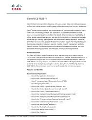
Product Description and InventoryAP7851 and AP7852 are <strong>Metered</strong> <strong>Rack</strong> <strong>Power</strong> <strong>Distribution</strong> <strong>Unit</strong>s (PDUs) that distribute power to devicesin the rack. They have a sensor that measures the current being used by the PDUs and their attacheddevices and they can be monitored through Web, Telnet, SNMP, or InfraStruXure Manager interfaces.Outlets—The outlets connect the PDU to equipment in yourrack or enclosure.Both PDUs have 24 outlets:• 20 IEC 320 C13• 4 IEC 320 C19Display Interface—The display interface on the <strong>Metered</strong>PDU shows the aggregate current being used by the PDU andits attached devices. An alarm occurs if the aggregate current isabove the high threshold value or below the low thresholdvalues that you configure.Plug—Each PDU has a plug that connects to a variety of APCequipment.• AP7851 has an IEC 320 C20 plug.• AP7852 has an IEC 309 1~ 230 V 16A plug.AP7851AP7852<strong>Metered</strong> <strong>Rack</strong> <strong>Power</strong> <strong>Distribution</strong> <strong>Unit</strong> 1
Product Description and InventoryAdditionaldocumentationThe PDU User’s Guide and the PDU Addendum are available on thesupplied CD and on the APC Web site: www.apc.com.The User’s Guide (.\doc\eng\usrguide.pdf) contains additionalinformation about the following topics related to the PDU:• Management interfaces• User accounts• Customizing setup•SecurityThe Addendum (.\doc\eng\addendum.pdf) contains additionalinformation about the following topics:• The Management Card Wizard• Configuration utilities• File transfersInventoryThe PDU is shipped with the following items:QuantityItem1 Configuration cable (940-0144)2 Cord retention tray (with 8 flat-head screwsand 24 wire ties)2 Mounting brackets (with 4 flat-head screws)1 APC Basic and <strong>Metered</strong> <strong>Power</strong> <strong>Distribution</strong><strong>Unit</strong>s Utility CD1 Warranty registration cardReceiving inspectionInspect the package and contents for shipping damage, and make surethat all parts were sent. Report any damage immediately to the shippingagent, and report missing contents, damage, or other problemsimmediately to APC or your APC reseller.Please recycleThe shipping materials are recyclable. Please save them forlater use, or dispose of them appropriately.InfraStruXure-certifiedThis product is certified for use in InfraStruXure systems. TheConfiguration section, beginning on page 8, does not apply to PDUs thatare part of InfraStruXure systems that are managed by an InfraStruXureManager.2 <strong>Metered</strong> <strong>Rack</strong> <strong>Power</strong> <strong>Distribution</strong> <strong>Unit</strong>
How to Install the PDUMounting optionsToolless mountingYou can install the PDU in one of two ways: using toolless mountingpegs (provided) or the mounting brackets (provided).• To install the PDU using the toolless mounting method, install thePDU in the rear of the NetShelter VX Enclosure, in the cablechannel directly behind the rear vertical mounting rails.• To install the PDU using the mounting brackets, install it on avertical mounting rail on your rack or enclosure.1. Slide the mounting pegs into the holes located in the channel in therear panel of the enclosure.2. Snap the PDU into place by pushing it downward until it locks intoposition.NoteYou can mount two PDUs on one side by using the toollessmounting method.4 <strong>Metered</strong> <strong>Rack</strong> <strong>Power</strong> <strong>Distribution</strong> <strong>Unit</strong>
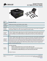
How to Install the PDUBracket-mountingTo mount the <strong>Rack</strong> PDU vertically in a NetShelter ® or any standardEIA-310 rack or enclosure:1. Attach the vertical-mounting brackets to the PDU.<strong>Metered</strong> <strong>Rack</strong> <strong>Power</strong> <strong>Distribution</strong> <strong>Unit</strong> 5
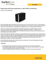
How to Install the PDU2. Install the PDU on a vertical mounting rail in your rack orenclosure.6 <strong>Metered</strong> <strong>Rack</strong> <strong>Power</strong> <strong>Distribution</strong> <strong>Unit</strong>
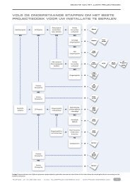
OperationDisplay interface - OK- Warning- OverloadAmpsPress and holdto invert display.Link - Rx/Tx10/100StatusAmps<strong>Metered</strong> <strong>Rack</strong> PDUResetSerial PortLine Indicator LED: Indicates normal (green), warning (yellow), andalarm (red) conditions.Control button: Press and hold for five seconds to view the orientation;hold for an additional five seconds to change the orientation.Ethernet port: Connects the PDU to your network, using a CAT5network cable.Status LED: Indicates the status of the Ethernet LAN connection andthe state of the <strong>Metered</strong> PDU.• Off–The PDU has no power.• Solid green–The PDU has valid TCP/IP settings.• Flashing green–The PDU does not have valid TCP/IP settings.• Solid orange–A hardware failure has been detected in the PDU.Contact Customer Support at a phone number on the back cover ofthis manual.• Flashing orange–The PDU is making BOOTP requests.Link LED: Indicates whether there is activity on the network.Serial port: Access internal menus by connecting this port (RJ-11modular port) to a serial port on your computer, using the suppliedserial cable (940-0144).Display of the current used by the PDU and attached devices: Showsthe aggregate current for the PDU.Reset switch: Resets the PDU without affecting the outlet status.<strong>Metered</strong> <strong>Rack</strong> <strong>Power</strong> <strong>Distribution</strong> <strong>Unit</strong> 7
Quick ConfigurationAPC Management CardWizardYou can use the APC Management Card Wizard at a Windows ® 98,Windows NT ® 4.0, Windows 2000, or Windows XP computer toconfigure a PDU.1. Insert the APC Basic and <strong>Metered</strong> <strong>Power</strong> <strong>Distribution</strong> <strong>Unit</strong>s UtilityCD into a computer on your network.2. Launch the Wizard, when prompted, or, if prompted to restart thecomputer, access the Wizard from the Start menu after thecomputer has restarted.3. Wait for the Wizard to discover the unconfigured PDU, then followthe on-screen instructions.NoteIf you leave the Start a Web browser when finishedoption enabled, you can use apc for both the user nameand password to access the PDU through your browser.BOOTP & DHCPconfigurationThe Boot Mode setting, a TCP/IP option in the PDU’s Network menu,identifies how TCP/IP settings will be defined. The possible settings areManual, DHCP only, BOOTP only, and DHCP & BOOTP (thedefault setting).NoteThe DHCP & BOOTP setting assumes that a properlyconfigured DHCP or BOOTP server is available to provideTCP/IP settings to the APC PDU. If these servers areunavailable, see “APC Management Card Wizard” on thispage, “Local access to the control console” on page 12, or“Remote access to the control console” on page 12 toconfigure the TCP/IP settings.With Boot Mode set to DHCP & BOOTP, the PDU attempts todiscover a properly configured server. It first searches for a BOOTPserver, and then a DHCP server. It repeats this pattern until it discovers aBOOTP or DHCP server.For more information, see “BOOTP” on page 10 or“DHCP” on page 11.<strong>Metered</strong> <strong>Rack</strong> <strong>Power</strong> <strong>Distribution</strong> <strong>Unit</strong> 9
Quick ConfigurationBOOTP. You can use an RFC951-compliant BOOTP server to configurethe TCP/IP settings for the PDU. If the BOOTP server is properlyconfigured, the PDU’s default setting (DHCP & BOOTP) for BOOTMode causes it to discover the BOOTP server.If a BOOTP server is unavailable, see “APC ManagementCard Wizard” on page 9, “Local access to the controlconsole” on page 12, or “Remote access to the controlconsole” on page 12 to configure TCP/IP settings.1. Enter the PDU’s MAC and IP addresses, the subnet mask anddefault gateway settings, and an optional bootup file name in theBOOTPTAB file of the BOOTP server.NoteFor the MAC address, look on the bottom of the PDU oron the Quality Assurance slip included in the package.2. When the PDU reboots, the BOOTP server provides it with theTCP/IP settings.– If you specified a bootup file name, the PDU attempts to transferthat file from the BOOTP server using TFTP or FTP. The PDUassumes all settings specified in the bootup file.– If you did not specify a bootup file name, the PDU can beconfigured remotely by using Telnet or by using the Webinterface: user name and password are both apc, by default. See“Remote access to the control console” on page 12 forconfiguration instruction.See alsoYou must use the APC Management Card Wizard tocreate the bootup file. To create a bootup file, see theBOOTP section in the Addendum.10 <strong>Metered</strong> <strong>Rack</strong> <strong>Power</strong> <strong>Distribution</strong> <strong>Unit</strong>
Quick ConfigurationDHCP. You can use a RFC2131/RFC2132-compliant DHCP server toconfigure the TCP/IP settings for the PDU.See alsoThis section briefly summarizes the PDU communicationwith a DHCP server. For more detail about how a DHCPserver is used to configure the network settings for thePDU, see “DHCP Configuration” in the User’s Guide.1. The PDU sends a DHCP request that uses the following to identifyitself:– Vendor Class Identifier (APC by default)– Client Identifier (by default, the PDU’s MAC address value)– User Class Identifier (by default, the identification of the PDU’sapplication firmware)2. A properly configured DHCP server responds with a DHCP offerthat includes all of the settings that the PDU needs for networkcommunication. The DHCP offer also includes the Vendor SpecificInformation option (DHCP option 43). By default, the PDUignores DHCP offers that do not encapsulate the APC cookie in theVendor Specific Information option using the followinghexidecimal format:Option 43 = 01 04 31 41 50 43where– The first byte (01) is the code– The second byte (04) is the length– The remaining bytes (31 41 50 43) are the APC cookieSee alsoSee your DHCP server documentation to add code tothe Vendor Specific Information option.You can use a local computer to disable the APC cookierequirement. For instructions on using a local computer, see“Local access to the control console” on page 12. To changethe control console’s DHCP Cookie Is setting, anAdvanced option in the TCP/IP menu, use Telnet oranother remote accessing method. To access the controlconsole, see “Remote access to the control console” onpage 12.<strong>Metered</strong> <strong>Rack</strong> <strong>Power</strong> <strong>Distribution</strong> <strong>Unit</strong> 11
Quick ConfigurationLocal access to thecontrol consoleYou can use a local computer to connect to the PDU to access the controlconsole.1. Select a serial port at the local computer, and disable any servicewhich uses that port.2. Use the configuration cable (940-0144) to connect the selected portto the serial port on the front panel of the PDU.3. Run a terminal program (such as HyperTerminal) and configurethe selected port for 9600 bps, 8 data bits, no parity, 1 stop bit, andno flow control, and save the changes.4. Press ENTER to display the User Name prompt.5. Use apc for the user name and password.6. See “Control console” on page 13 to finish the configuration.Remote access to thecontrol consoleFrom any computer on the same subnet as the PDU, you can use ARPand Ping to assign an IP address to the PDU, and then use Telnet toaccess that PDU’s control console and configure the needed TCP/IPsettings.NoteAfter the PDU has its IP address configured, you can useTelnet, without first using ARP and Ping, to access thatPDU.1. Use ARP to define an IP address for the PDU, and use the PDU’sMAC address in the ARP command. For example, to define an IPaddress of 156.205.14.141 for the PDU that has a MAC address of00 c0 b7 63 9f 67, use one of the following commands:– Windows command format:arp -s 156.205.14.141 00-c0-b7-63-9f-67– LINUX command format:arp -s 156.205.14.141 00:c0:b7:63:9f:67NoteFor the MAC address, look on the bottom of the PDU or onthe Quality Assurance slip included in the package.2. Use Ping with a size of 113 bytes to assign the IP address definedby the ARP command. For example:– Windows command format:ping 156.205.14.141 -l 113– LINUX command format:ping 156.205.14.141 -s 11312 <strong>Metered</strong> <strong>Rack</strong> <strong>Power</strong> <strong>Distribution</strong> <strong>Unit</strong>
Quick Configuration3. Use Telnet to access the PDU at its newly assigned IP address. Forexample:telnet 156.205.14.1414. Use apc for both user name and password.5. See “Control console” on this page to finish the configuration.Control consoleAfter you log on at the control console, as described in “Local access tothe control console” on page 12 or “Remote access to the controlconsole” on page 12:1. Choose Network from the Control Console menu.2. Choose TCP/IP from the Network menu.3. If you are not using a BOOTP or DHCP server to configure theTCP/IP settings, select the Boot Mode menu. Select Manual bootmode, and then press ESC to return to the TCP/IP menu. (Changeswill take effect when you log out.)4. Set the System IP, Subnet Mask, and Default Gateway addressvalues.5. Press CTRL-C to exit to the Control Console menu.6. Log out (option 4 in the Control Console menu).NoteIf you disconnected a cable during the proceduredescribed in “Local access to the control console” onpage 12, reconnect that cable and restart the associatedservice.<strong>Metered</strong> <strong>Rack</strong> <strong>Power</strong> <strong>Distribution</strong> <strong>Unit</strong> 13
How to Access a Configured PDUOverviewAfter the PDU is running on your network, you can use several differentinterfaces to access the PDU.NoteTo use the interfaces identified here, see the User’s Guideand the Addendum.Web interface Use Microsoft ® Internet Explorer 5.0 (and higher) or Netscape ® 4.0.8(and higher) to configure PDU options or to view the Event log.1. Address the PDU by its IP address or DNS name (if configured).2. Enter the user name and password (by default, apc and apc for anAdministrator, or device and apc for a Device Manager).TelnetYou can use Telnet to access a PDU’s control console from anycomputer on the same subnet.1. At a command prompt, use the following command line, and pressENTER:telnet As , use the PDU’s IP address or DNS name (ifconfigured).2. Enter the user name and password (by default, apc and apc for anAdministrator, or device and apc for a Device Manager).SNMPFTPAfter you add the <strong>Power</strong>Net MIB to a standard SNMP MIB browser,you can use that browser for SNMP access to the PDU. The default readcommunity name is public; the default read/write community name isprivate.You can use FTP (enabled by default) to download new firmware to thePDU, or to access a copy of the PDU’s event logs.1. At a command prompt, use the following command line, and pressENTER:ftp As , use the PDU’s IP address.2. Enter the user name and password (by default, apc and apc for anAdministrator, or device and apc for a Device Manager).14 <strong>Metered</strong> <strong>Rack</strong> <strong>Power</strong> <strong>Distribution</strong> <strong>Unit</strong>
How to Recover From a Lost PasswordYou can use a local computer that connects to the PDU through the serialport on the front of the unit.1. Select a serial port at a local computer, and disable any service thatuses the port.2. Use the configuration cable (940-0144) to connect the selected portto the serial port on the front panel of the PDU.3. Run a terminal program (such as HyperTerminal) and configurethe selected port for 9600 bps, 8 data bits, no parity, 1 stop bit, andno flow control, and save the changes.4. Press ENTER to display the User Name prompt.5. Press the Reset button on the PDU, which causes the PDU torestart, a process that typically takes approximately 15 seconds.6. Press ENTER as many times as necessary to redisplay the UserName prompt, then use apc for the user name and password. (Ifyou take longer than 30 seconds to log on after the User Nameprompt is redisplayed, you must start the login procedure again atstep 4.)7. From the Control Console menu, select System, then UserManager.8. Select Administrator, and change the User Name and Passwordsettings, both of which are now defined as apc.9. Press CTRL-C and log off.NoteReconnect any cable that you disconnected in step 2 andrestart any service that you disabled in step 1.<strong>Metered</strong> <strong>Rack</strong> <strong>Power</strong> <strong>Distribution</strong> <strong>Unit</strong> 15
How to Download Firmware UpdatesSee alsoFor a complete description on how to download a firmwareupgrade for your PDU, see the Addendum on the providedAPC Basic and <strong>Metered</strong> <strong>Power</strong> <strong>Distribution</strong> <strong>Unit</strong>s UtilityCD.You can use a local computer that connects to the PDU through the serialport on the front of the unit.1. Select a serial port at the local computer, and disable any servicethat uses that port.2. Use the configuration cable (940-0144) to connect the selected portto the RJ-12 serial port on the front panel of the PDU.3. Run a terminal program (such as HyperTerminal) and configurethe selected port for 9600 bps, 8 data bits, no parity, 1 stop bit, andno flow control. Save the changes.4. Press ENTER twice to display the User Name prompt.5. Enter your user name and password (both apc, for administratorsonly) and press ENTER.6. From the Control Console menu, select System, then Tools, thenXMODEM.7. The system will prompt you with Perform transfer withXMODEM -CRC? Type Yes and press ENTER.8. The system will then prompt you to choose a transfer rate and tochange your terminal settings to match the transfer rate. PressENTER to set the PDU to accept the download.9. In the terminal program, send the file using the XMODEMprotocol. Upon completion of the transfer, the console will promptyou to restore the baud rate to normal.CautionDo not interrupt the download.The PDU will reboot when the download is complete.NoteUpgrading the firmware will not interfere with theoperation of the outlets.16 <strong>Metered</strong> <strong>Rack</strong> <strong>Power</strong> <strong>Distribution</strong> <strong>Unit</strong>
SpecificationsElectrical AP7851 AP7852Nominal input voltageAcceptable input voltageInput frequency230 V± 10% Nominal input voltage47– 63 HzCord length 3 ft 10 ftInput connectorsIEC 309 1~ 230 V16A plug16 A IEC 320 C20 plugOutput connectorsMaximum total currentdraw(20) IEC 320 C13; (4) IEC 320 C19 outlets16 APhysicalSize (H × W × D)WeightShipping weight63.75 ×2.19×1.73 in(161.93 ×5.56×4.39 cm)9.5 lb (4.3 kg)17 lb (7.7 kg)EnvironmentalElevation (above MSL)OperatingStorageTemperatureOperatingStorageHumidityOperatingStorage0–15,000 ft (0–4500 m)0–50,000 ft (0–15 000 m)–5 to 45° C (23 to 115° F)–25 to 65° C (–13 to 149° F)5–95% RH Non-condensing5–95% RH Non-condensingApprovalsEMC verificationEN 55022 Class A, AS/NZS 3548 Class A,IEC 61000-3-2, IEC 61000-3-3, EN55024Safety verification VDE 0805, CE , EN 60950, IEC 60950<strong>Metered</strong> <strong>Rack</strong> <strong>Power</strong> <strong>Distribution</strong> <strong>Unit</strong> 17
Warranty and ServiceLimited warrantyAPC warrants the PDU to be free from defects in materials andworkmanship for a period of two years from the date of purchase. Itsobligation under this warranty is limited to repairing or replacing, at itsown sole option, any such defective products. This warranty does notapply to equipment that has been damaged by accident, negligence, ormisapplication or has been altered or modified in any way. Thiswarranty applies only to the original purchaser.Warranty limitationsExcept as provided herein, APC makes no warranties, express orimplied, including warranties of merchantability and fitness for aparticular purpose. Some jurisdictions do not permit limitation orexclusion of implied warranties; therefore, the aforesaid limitation(s) orexclusion(s) may not apply to the purchaser.Except as provided above, in no event will APC be liable for direct,indirect, special, incidental, or consequential damages arising out ofthe use of this product, even if advised of the possibility of suchdamage.Specifically, APC is not liable for any costs, such as lost profits orrevenue, loss of equipment, loss of use of equipment, loss of software,loss of data, costs of substitutes, claims by third parties, or otherwise.This warranty gives you specific legal rights and you may also haveother rights, which vary according to jurisdiction.Obtaining serviceTo obtain support for problems with your PDU:01. Note the serial number and date of purchase. The serial number islocated on the safety label on the back of the PDU.2. Contact Customer Support at a phone number located on the backcover. A technician will try to help you solve the problem byphone.3. If you must return the product, the technician will give you a returnmaterial authorization (RMA) number. If the warranty expired, youwill be charged for repair or replacement.4. Pack the unit carefully. The warranty does not cover damagesustained in transit. Enclose a letter with your name, address, RMAnumber and daytime phone number; a copy of the sales receipt;and a check as payment, if applicable.5. Mark the RMA number clearly on the outside of the shippingcarton.6. Ship by insured, prepaid carrier to the address provided by theCustomer Support technician.18 <strong>Metered</strong> <strong>Rack</strong> <strong>Power</strong> <strong>Distribution</strong> <strong>Unit</strong>
Life-Support PolicyGeneral policyAmerican <strong>Power</strong> Conversion (APC) does not recommend the use of anyof its products in the following situations:• In life-support applications where failure or malfunction of theAPC product can be reasonably expected to cause failure of thelife-support device or to affect significantly its safety oreffectiveness.• In direct patient care.APC will not knowingly sell its products for use in such applicationsunless it receives in writing assurances satisfactory to APC that (a) therisks of injury or damage have been minimized, (b) the customerassumes all such risks, and (c) the liability of American <strong>Power</strong>Conversion is adequately protected under the circumstances.Examples of life-supportdevicesThe term life-support device includes but is not limited to neonataloxygen analyzers, nerve stimulators (whether used for anesthesia, painrelief, or other purposes), autotransfusion devices, blood pumps,defibrillators, arrhythmia detectors and alarms, pacemakers,hemodialysis systems, peritoneal dialysis systems, neonatal ventilatorincubators, ventilators (for adults and infants), anesthesia ventilators,infusion pumps, and any other devices designated as “critical” by theU.S. FDA.Hospital-grade wiring devices and leakage current protection may beordered as options on many APC UPS systems. APC does not claim thatunits with these modifications are certified or listed as hospital-grade byAPC or any other organization. Therefore these units do not meet therequirements for use in direct patient care.<strong>Metered</strong> <strong>Rack</strong> <strong>Power</strong> <strong>Distribution</strong> <strong>Unit</strong> 19
APC Worldwide Customer SupportCustomer support for this or any other APC product is available at no charge in any of the following ways:• Visit the APC Web site to find answers to frequently asked questions (FAQs), to accessdocuments in the APC Knowledge Base, and to submit customer support requests.– www.apc.com (Corporate Headquarters)Connect to localized APC Web sites for specific countries, each of which provides customersupport information.– www.apc.com/support/Global support with FAQs, knowledge base, and e-support.• Contact an APC Customer Support center by telephone or e-mail.– Regional centers:Direct InfraStruXure Customer SupportAPC headquarters U.S., CanadaLatin AmericaEurope, Middle East, Africafif(1)(877)537-0607 (toll free)(1)(800)800-4272 (toll free)(1)(401)789-5735 (USA)(353)(91)702055 (Ireland)Japan (0) 35434-2021Australia, New Zealand, South Pacífic(61) (2) 9955 9366 (Australia)– Local, country-specific centers: go to www.apc.com/support/contact for contact information.Contact the APC representative or other distributor from whom you purchased your APC product forinformation on how to obtain local customer support.Entire contents copyright © 2003 American <strong>Power</strong> Conversion. All rights reserved.Reproduction in whole or in part without permission is prohibited. APC, the APC logo,InfraStruXure, and NetShelter are trademarks of American <strong>Power</strong> Conversion Corporationand may be registered in some jurisdictions. All other trademarks, product names, andcorporate names are the property of their respective owners and are used for informationalpurposes only.*990-1666-001*990-1666-001 09/2003