Transcript - IPC Training Home Page
Transcript - IPC Training Home Page
Transcript - IPC Training Home Page
You also want an ePaper? Increase the reach of your titles
YUMPU automatically turns print PDFs into web optimized ePapers that Google loves.
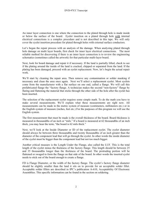
DVD-97CC <strong>Transcript</strong>An inner layer connection is one where the connection to the plated through hole is made insideor below the surface of the board. Eyelet insertion on a plated through hole with internalelectrical connections is a complex procedure and is not described in this tape. We will onlycover the eyelet insertion procedure for plated through holes with external surface conductors.Let’s began the repair process with an analysis of the damage. When analyzing plated throughhole damage on multi layer boards, first check for inner layer electrical connections. The mostreliable method for discovering if there is an inner layer connection is to review the engineeringschematics (sometimes called the artwork) for that particular multi-layer board.Next, look for board damage and repair it if necessary. If the land is partially lifted, check to seeif the plating around the inside of the land is cracked, chipped or separated from the land. If theplating has been damaged, proceed with an eyelet replacement. Now, let’s begin the actual repairwork.We’ll start by cleaning the repair area. Then remove any contamination or solder masking ifnecessary and clean the area once again. Next we’ll select a replacement eyelet. Most eyeletscome from the manufacturer with a flat surface on one end, called a flange. We will call thisprefabricated flange the “factory flange. A technician makes the second “non-factory” flange byflaring and flattening the material that sticks through the other side of the hole after the eyelet hasbeen inserted.The selection of the replacement eyelet requires some simple math. To do the math you have tomake several measurements. We’ll explain what these measurements are right now. Allmeasurements can be made in the metric system of measure (centimeters, millimeters etc.) or inthe English system of measure (inches, feet etc.) For the purposes of this program we will use theEnglish system.The first measurement that must be made is the overall thickness of the board. Board thickness ismeasured in thousandths of an inch or “mils.” If a board is measured at 62 thousandths of an inchthick, you may hear the term, “the board is 62 mils thick.”Next, we’ll look at the Inside Diameter or ID of the replacement eyelet. The eyelet diametershould always be between three thousandths and twenty thousandths of an inch greater than thediameter of the component lead that will go through the eyelet. In other words the inside diameterof the eyelet must be bigger than the component lead but not too much bigger.Another critical measure is the Length Under the Flange, also called the LUF. This is the totallength of the eyelet minus the thickness of the factory flange. This length should be between 25and 35 thousandths longer than the thickness of the board. The protruding portion will beflattened or swaged to form the flange on that side of the board. In other words the inserted eyeletneeds to stick out of the board enough to create a flange.FD is Flange Diameter, or the width of the factory flange. The eyelet’s factory flange diametershould be slightly smaller than the land it sits on to provide for an acceptable solder fillet.Acceptable solder fillets are described in <strong>IPC</strong>’s publication A-610, Acceptability Of ElectronicAssemblies. This specific information can be found in the section on soldering.2


