Introduction to Traveling-Wave antennas.pdf
Introduction to Traveling-Wave antennas.pdf
Introduction to Traveling-Wave antennas.pdf

Create successful ePaper yourself
Turn your PDF publications into a flip-book with our unique Google optimized e-Paper software.
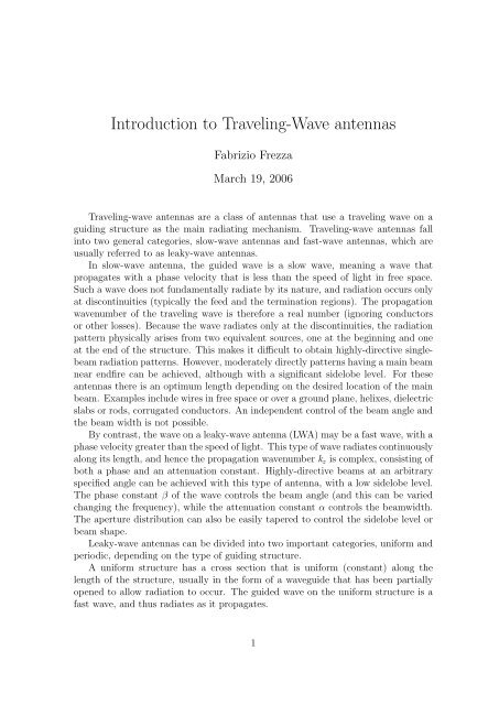
<strong>Introduction</strong> <strong>to</strong> <strong>Traveling</strong>-<strong>Wave</strong> <strong>antennas</strong>Fabrizio FrezzaMarch 19, 2006<strong>Traveling</strong>-wave <strong>antennas</strong> are a class of <strong>antennas</strong> that use a traveling wave on aguiding structure as the main radiating mechanism. <strong>Traveling</strong>-wave <strong>antennas</strong> fallin<strong>to</strong> two general categories, slow-wave <strong>antennas</strong> and fast-wave <strong>antennas</strong>, which areusually referred <strong>to</strong> as leaky-wave <strong>antennas</strong>.In slow-wave antenna, the guided wave is a slow wave, meaning a wave thatpropagates with a phase velocity that is less than the speed of light in free space.Such a wave does not fundamentally radiate by its nature, and radiation occurs onlyat discontinuities (typically the feed and the termination regions). The propagationwavenumber of the traveling wave is therefore a real number (ignoring conduc<strong>to</strong>rsor other losses). Because the wave radiates only at the discontinuities, the radiationpattern physically arises from two equivalent sources, one at the beginning and oneat the end of the structure. This makes it difficult <strong>to</strong> obtain highly-directive singlebeamradiation patterns. However, moderately directly patterns having a main beamnear endfire can be achieved, although with a significant sidelobe level. For these<strong>antennas</strong> there is an optimum length depending on the desired location of the mainbeam. Examples include wires in free space or over a ground plane, helixes, dielectricslabs or rods, corrugated conduc<strong>to</strong>rs. An independent control of the beam angle andthe beam width is not possible.By contrast, the wave on a leaky-wave antenna (LWA) may be a fast wave, with aphase velocity greater than the speed of light. This type of wave radiates continuouslyalong its length, and hence the propagation wavenumber k z is complex, consisting ofboth a phase and an attenuation constant. Highly-directive beams at an arbitraryspecified angle can be achieved with this type of antenna, with a low sidelobe level.The phase constant β of the wave controls the beam angle (and this can be variedchanging the frequency), while the attenuation constant α controls the beamwidth.The aperture distribution can also be easily tapered <strong>to</strong> control the sidelobe level orbeam shape.Leaky-wave <strong>antennas</strong> can be divided in<strong>to</strong> two important categories, uniform andperiodic, depending on the type of guiding structure.A uniform structure has a cross section that is uniform (constant) along thelength of the structure, usually in the form of a waveguide that has been partiallyopened <strong>to</strong> allow radiation <strong>to</strong> occur. The guided wave on the uniform structure is afast wave, and thus radiates as it propagates.1
2 <strong>Introduction</strong> <strong>to</strong> TWAA periodic leaky-wave antenna structure is one that consists of a uniform structurethat supports a slow (non radiating) wave that has been periodically modulatedin some fashion. Since a slow wave radiates at discontinuities, the periodic modulations(discontinuities) cause the wave <strong>to</strong> radiate continuously along the length ofthe structure. From a more sophisticated point of view, the periodic modulation createsa guided wave that consists of an infinite number of space harmonics (Floquetmodes). Although the main (n = 0) space harmonic is a slow wave, one of the spaceharmonics (usually the n = −1) is designed <strong>to</strong> be a fast wave, and hence a radiatingwave.A typical example of a uniform leaky-wave antenna is a rectangular waveguidewith a longitudinal slot. This simple structure illustrates the basic properties common<strong>to</strong> all uniform leaky-wave <strong>antennas</strong>.√The fundamental TE 10 waveguide mode is a fast wave, with β = ko 2 − ( ) 2πalower than k o . The radiation causes the wavenumber k z of the propagating modewithin the open waveguide structure <strong>to</strong> become complex. By means of an applicationof the stationary-phase principle, it can be found in fact that:βk o=cv ph= λ oλg ≃ sin θ m (1)where θ m is the angle of maximum radiation taken from broadside. As is typical fora uniform LWA, the beam cannot be scanned <strong>to</strong>o close <strong>to</strong> broadside (θ m = 0), sincethis corresponds <strong>to</strong> the cu<strong>to</strong>ff frequency of the waveguide. In addition, the beamcannot be scanned <strong>to</strong>o close <strong>to</strong> endfire (θ m = 90 ◦ ) since this requires operation atfrequencies significantly above cu<strong>to</strong>ff, where higher-order modes can propagate, atleast for an air-filled waveguide. Scanning is limited <strong>to</strong> the forward quadrant only(0 < θ m < π ), for a wave traveling in the positive z direction.2Figure 1: Slotted guide (patented by W. W. Hansen in 1940)This one-dimensional (1D) leaky-wave aperture distribution results in a “fanbeam” having a narrow beam in the xz plane (H plane), and a broad beam in thecross-plane. A pencil beam can be created by using an array of such 1D radia<strong>to</strong>rs.Unlike the slow-wave structure, a very narrow beam can be created at any angleby choosing a sufficiently small value of α. A simple formula for the beam width,European School of Antennas
3 <strong>Introduction</strong> <strong>to</strong> TWAmeasured between half power points (3dB), is:1∆θ ≃L(2)λ ocos θ mwhere L is the length of the leaky-wave antenna, and ∆θ is expressed in radians. For90% of the power radiated it can be assumed:L≃ 0.18αλ o k o⇒ ∆θ ∝ α k oSince leakage occurs over the length of the slit in the waveguiding structure, thewhole length constitutes the antenna’s effective aperture unless the leakage rate is sogreat that the power has effectively leaked away before reaching the end of the slit.A large attenuation constant implies a short effective aperture, so that the radiatedbeam has a large beamwidth. Conversely, a low value of α results in a longeffective aperture and a narrow beam, provided the physical aperture is sufficientlylong.Since power is radiated continuously along the length, the aperture field of a leakywaveantenna with strictly uniform geometry has an exponential decay (usually slow),so that the sidelobe behavior is poor. The presence of the sidelobes is essentially due<strong>to</strong> the fact that the structure is finite along z.When we change the cross-sectional geometry of the guiding structure <strong>to</strong> modifythe value of α at some point z, however, it is likely that the value of β at that pointis also modified slightly. However, since β must not be changed, the geometry mustbe further altered <strong>to</strong> res<strong>to</strong>re the value of β, thereby changing α somewhat as well.In practice, this difficulty may require a two-step process. The practice is then <strong>to</strong>vary the value of α slowly along the length in a specified way while maintaining βconstant (that is the angle of maximum radiation), so as <strong>to</strong> adjust the amplitude ofthe aperture distribution A(z) <strong>to</strong> yield the desired sidelobe performance.We can divide uniform leaky-wave <strong>antennas</strong> in<strong>to</strong> air-filled ones and partiallydielectric-filled ones. In the first case, since the transverse wavenumber k t is then aconstant with frequency, the beamwidth of the radiation remains exactly constantas the beam is scanned by varying the frequency. In fact, since:where:cos 2 θ m = 1 −( βk o) 2(3)k 2 o = k 2 t + β 2 ⇒( βk o) 2= 1 −(ktk o) 2⇒ cos θ m = k t⇒ ∆θ ≃ 2πk o k t L = λ cLEuropean School of Antennas
4 <strong>Introduction</strong> <strong>to</strong> TWAindependent of frequency. On the contrary, when the guiding structure is partlyfilled with dielectric, the transverse wavenumber k t is a function of frequency, sothat ∆θ changes as the beam is frequency scanned. On the other hand, with respect<strong>to</strong> frequency sensitivity, i.e., how quickly the beam angle scans as the frequency isvaried, the partly dielectric-loaded structure can scan over a larger range of anglesfor the same frequency change and is therefore preferred.Figure 2: Dispersion Curves (effective refractive index)In response <strong>to</strong> requirements at millimeter wavelengths, the new <strong>antennas</strong> weregenerally based on lower-loss open waveguides. One possible mechanism <strong>to</strong> obtainradiation is foreshortening a side. Let us consider for example the nonradiativedielectric guide (NRD).Figure 3: Non Radiative Dielectric guideThe spacing a between the metal plates is less than λo so that all junctions and2discontinuities (also curves) that maintain symmetry become purely reactive, insteadof possessing radiative content. When the vertical metal plates in the NRD guide areEuropean School of Antennas
5 <strong>Introduction</strong> <strong>to</strong> TWAsufficiently long, the dominant mode field is completely bound, since it has decayed<strong>to</strong> negligible values as it reaches the upper and lower open ends. If the upper portionof the plates is foreshortened, a traveling-wave field of finite amplitude then existsalong the length of the upper open end, and if the dominant NRD guide mode is fast(it can be fast or slow depending on the frequency), power will be radiated away atan angle from this open end.Another possible mechanism is asymmetry. In the asymmetrical NRD guideantenna the structure is first bisected horizontally <strong>to</strong> provide radiation from one endonly; since the electric field is purely vertical in this midplane, the field structure innot altered by the bisection.Figure 4: Asymmetrical Non Radiative Dielectric guideAn air gap is then introduced in<strong>to</strong> the dielectric region <strong>to</strong> produce asymmetry.As a result, a small amount of net horizontal electric field is created, which producesa mode in the parallel-plate air region, which is a TEM mode, which propagates atan angle between the parallel plates until it reaches the open end and leaks away. Itis necessary <strong>to</strong> maintain the parallel plates in the air region sufficiently long that thevertical electric field component of the original mode (represented in the stub guideby the below-cu<strong>to</strong>ff TM 1 mode) has decayed <strong>to</strong> negligible values at the open end.Then the TEM mode, with its horizontal electric field, is the only field left, and thefield polarization is then essentially pure (the discontinuity at the open end does notintroduce any cross-polarized field components).Groove guide is a low-loss open waveguide for millimeter waves, somewhat similar<strong>to</strong> the NRD guide: the dielectric central region is replaced by an air region of greaterwidth. The field again decays exponentially vertically in the regions of narrowerwidth above and below.The leaky-wave antenna is created by first bisecting the offset groove guide horizontally.It also resembles a rectangular waveguide stub loaded. When the stub isoff-centered, the structure will radiate. When the offset is increased, the attenuationconstant α will increase and the beamwidth will increase <strong>to</strong>o. When the stubis placed all the way <strong>to</strong> one end, the result is an L-shaped structure that radiatesvery strongly. In addition, it is found that the value of β changes very little as theEuropean School of Antennas
6 <strong>Introduction</strong> <strong>to</strong> TWAFigure 5: Groove guidestub is moved, and α varies over a very large range. This feature allows <strong>to</strong> taper theantenna aperture <strong>to</strong> control sidelobes. The fact that the L-shaped structure stronglyleaks may also be related <strong>to</strong> another leakage mechanism: the use of leaky highermodes. In particular, it may be found that all the groove-guide higher modes areleaky. For example, let us consider the first higher antisymmetric mode. Becauseof the symmetry of the structure and the directions of the electric-field lines, thestructure can be bisected twice <strong>to</strong> yield the L-shaped.Figure 6: Sketches showing the transition from the T E 20 mode in the full grooveguide, on the left, <strong>to</strong> the L-shaped antenna structure on the right. The transitioninvolves two successive bisections, neither of which disturb the field distribution. Thearrows represent electric field directions.The antenna may be analyzed using a transverse equivalent network based on aT-junction network. The expressions for the network elements are in simple closedforms and yet are very accurate.Usually, the stub length needs only <strong>to</strong> be about a half wavelength or less if the stubis narrow. To exploit the possibility of printed-circuit techniques, a printed-circuitversion of the previous structure has been developed. In this way the fabricationprocess could make use of pho<strong>to</strong>lithography, and the taper design for sidelobe controlcould be handled au<strong>to</strong>matically in the fabrication. The transverse equivalent networkfor this new antenna structure is slightly more complicated than the previous, andthe expressions for the network elements must be modified appropriately <strong>to</strong> takeEuropean School of Antennas
7 <strong>Introduction</strong> <strong>to</strong> TWAFigure 7: Equivalent Transverse Transmission Network of Groove guidethe dielectric medium in<strong>to</strong> account. Moreover, above the transformer, an additionalsusceptance B s appears.The stub and main guides are no longer the same, so their wavenumbers andcharacteristic admittances are also different.Figure 8: Effect of the structure asymmetry on the propagation characteristicsAgain, α can be varied by changing the slot location d. However, it was foundthat a ′ is also a good parameter <strong>to</strong> change for this purpose.An interesting variation of the previous structures has been developed and analyzed.It is based on a ridge waveguide rather than a rectangular waveguide. In thestructures based on rectangular waveguide, the asymmetry was achieved by placingthe stub guide, or locating the longitudinal slot, off-center on the <strong>to</strong>p surface. Herethe <strong>to</strong>p surface is symmetrical, and the asymmetry is created by having unequal stublengths on each side under the main-guide portion.The transverse equivalent networks, <strong>to</strong>gether with the associated expressions forthe network elements, were adapted and extended <strong>to</strong> apply <strong>to</strong> these new structures.European School of Antennas
8 <strong>Introduction</strong> <strong>to</strong> TWAFigure 9: Effect of the stub width on the phase and the attenuation constantsAn analysis of the antenna behavior indicates that this geometry effectively permitsindependent control of the angle of maximum radiation θ m and the beamwidth ∆θ.Let us define two geometric parameters: the relative average arm length bm whereab m = b l+b r, and the relative unbalance ∆b2 b m, where ∆b = b l−b r.2Figure 10: Ridge guide.It then turns out that by changing bm aone can adjust the value of withoutaltering α k omuch and that by changing ∆bb mone can vary α k oover a large range withoutaffecting β k omuch. The taper design for controlling the sidelobe level would thereforeinvolve only the relative unbalance ∆bb m. The transverse equivalent network is slightlycomplicated by the presence of two additional changes in height of the waveguide,which can be modeled by means of shunt susceptances and ideal transformer. Theideal transformer accounts for the change in the characteristic impedance, while thes<strong>to</strong>ring of reactive energy is taken in<strong>to</strong> account through the susceptance.Scanning arrays achieve scanning in two dimensions by creating a one-dimensionalphased array of leaky-wave line-source <strong>antennas</strong>. The individual line sources areβk oEuropean School of Antennas
9 <strong>Introduction</strong> <strong>to</strong> TWAFigure 11: Equivalent Transverse Transmission Network of Ridge guidescanned in elevation by varying the frequency. Scanning in the cross plane, andtherefore in azimuth, is produced by phase shifters arranged in the feed structureof the one-dimensional array of line sources. The radiation will therefore occur inpencil-beam form and will scan in both elevation and azimuth in a conical-scanmanner. The spacing between the line sources is chosen such that no grating lobesoccur, and accurate analyses show that no blind spots appear anywhere.The described arrays have been analyzed accurately by unit-cell approach thattakes in<strong>to</strong> account all mutual-coupling effects. Each unit cell incorporates an individualline-source antenna, but in the presence of all the others. The radiatingtermination on the unit cell modifies the transverse equivalent network. A key newfeature of the array analysis is therefore the determination of the active admittanceof the unit cell in the two-dimensional environment as a function of scan angle.If the values of β and α did not change with phase shift, the scan would beexactly conical. However, it is found that these values change only a little, so thatthe deviation from conical scan is small. We next consider whether or not blind spotsare present. Blind spots refer <strong>to</strong> angles at which the array cannot radiate or receiveany power; if a blind spot occurred at some angle, therefore, the value of α wouldrapidly go <strong>to</strong> zero at that angle of scan. To check for blind spots, we would thenlook for any sharp dips in the curves of α k oas a function of scan angle. No such dipswere ever found. Typical data of this type exhibit fairly flat behavior for α k ountil thecurves drop quickly <strong>to</strong> zero as they reach the end of the conical scan range, wherethe beam hits the ground.European School of Antennas
10 <strong>Introduction</strong> <strong>to</strong> TWAReferences[1] C. H. Walter: <strong>Traveling</strong> <strong>Wave</strong> Antennas, McGraw Hill, Dover, 1965-1970,reprinted by Peninsula Publishing, Los Al<strong>to</strong>s California, 1990.[2] N. Marcuvitz: <strong>Wave</strong>guide Handbook, MCGraw Hill, 1951, reprinted by PeterPeregrinus Ltd, London, 1986.[3] V. V. Shevchenko, Continous transitions in open waveguides: introduction <strong>to</strong> thetheory, The Golden Press, Boulder, Colorado 1971; Russian Edition, Moscow,1969.[4] T. Rozzi and M. Mongiardo, Open Electromagnetic <strong>Wave</strong>guides, The Institutionof Electrical Engeneers, London, 1997.[5] M. J. Ablowitz and A. S. Fokes, Complex variables: <strong>Introduction</strong> and Applications,second edition, Cambridge University Press, 2003.[6] A. A. Oliner (principal investiga<strong>to</strong>r), Scannable millimeter wave arrays, FinalReport on RADC Contract No. F19628-84-K-0025, Polytechnic University, NewYork, 1988.[7] A. A. Oliner, Radiating periodic structures: analysis in terms of k vs. β diagrams,short course on Microwave Field and Network Techniques, Polytechnic Instituteof Brooklyn, New York, 1963.[8] A. A. Oliner (principal investiga<strong>to</strong>r), Lumped-Element and Leaky-<strong>Wave</strong> Antennasfor Millimeter <strong>Wave</strong>s, Final Report on RADC Contract No. F19628-81-K-0044,Polytechnic Institute of New York, 1984.[9] F. J. Zucker, Surface and leaky-wave <strong>antennas</strong>, Chapter 16.European School of Antennas