MISR: In-Flight Radiometric Calibration and Characterization Plan
MISR: In-Flight Radiometric Calibration and Characterization Plan
MISR: In-Flight Radiometric Calibration and Characterization Plan

Create successful ePaper yourself
Turn your PDF publications into a flip-book with our unique Google optimized e-Paper software.
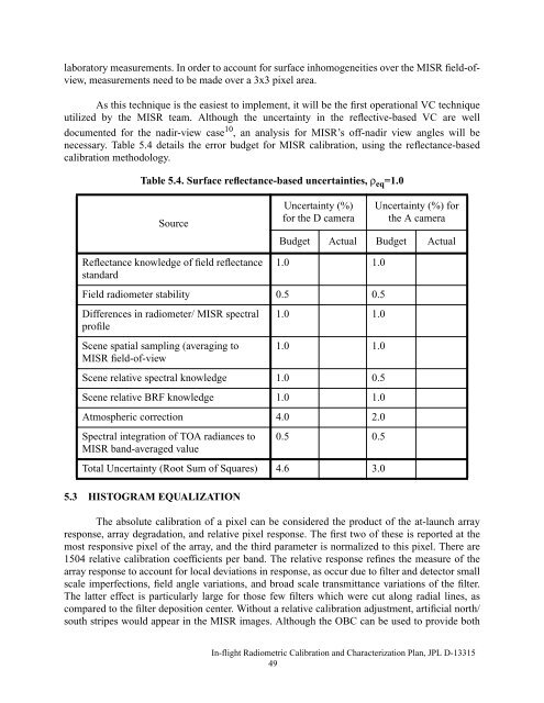
laboratory measurements. <strong>In</strong> order to account for surface inhomogeneities over the <strong>MISR</strong> field-ofview,measurements need to be made over a 3x3 pixel area.As this technique is the easiest to implement, it will be the first operational VC techniqueutilized by the <strong>MISR</strong> team. Although the uncertainty in the reflective-based VC are welldocumented for the nadir-view case 10 , an analysis for <strong>MISR</strong>’s off-nadir view angles will benecessary. Table 5.4 details the error budget for <strong>MISR</strong> calibration, using the reflectance-basedcalibration methodology.Table 5.4. Surface reflectance-based uncertainties, ρ eq =1.0SourceReflectance knowledge of field reflectancest<strong>and</strong>ardUncertainty (%)for the D cameraUncertainty (%) forthe A cameraBudget Actual Budget Actual1.0 1.0Field radiometer stability 0.5 0.5Differences in radiometer/ <strong>MISR</strong> spectralprofileScene spatial sampling (averaging to<strong>MISR</strong> field-of-view1.0 1.01.0 1.0Scene relative spectral knowledge 1.0 0.5Scene relative BRF knowledge 1.0 1.0Atmospheric correction 4.0 2.0Spectral integration of TOA radiances to<strong>MISR</strong> b<strong>and</strong>-averaged value0.5 0.5Total Uncertainty (Root Sum of Squares) 4.6 3.05.3 HISTOGRAM EQUALIZATIONThe absolute calibration of a pixel can be considered the product of the at-launch arrayresponse, array degradation, <strong>and</strong> relative pixel response. The first two of these is reported at themost responsive pixel of the array, <strong>and</strong> the third parameter is normalized to this pixel. There are1504 relative calibration coefficients per b<strong>and</strong>. The relative response refines the measure of thearray response to account for local deviations in response, as occur due to filter <strong>and</strong> detector smallscale imperfections, field angle variations, <strong>and</strong> broad scale transmittance variations of the filter.The latter effect is particularly large for those few filters which were cut along radial lines, ascompared to the filter deposition center. Without a relative calibration adjustment, artificial north/south stripes would appear in the <strong>MISR</strong> images. Although the OBC can be used to provide both<strong>In</strong>-flight <strong>Radiometric</strong> <strong>Calibration</strong> <strong>and</strong> <strong>Characterization</strong> <strong>Plan</strong>, JPL D-1331549