MISR: In-Flight Radiometric Calibration and Characterization Plan
MISR: In-Flight Radiometric Calibration and Characterization Plan
MISR: In-Flight Radiometric Calibration and Characterization Plan

You also want an ePaper? Increase the reach of your titles
YUMPU automatically turns print PDFs into web optimized ePapers that Google loves.
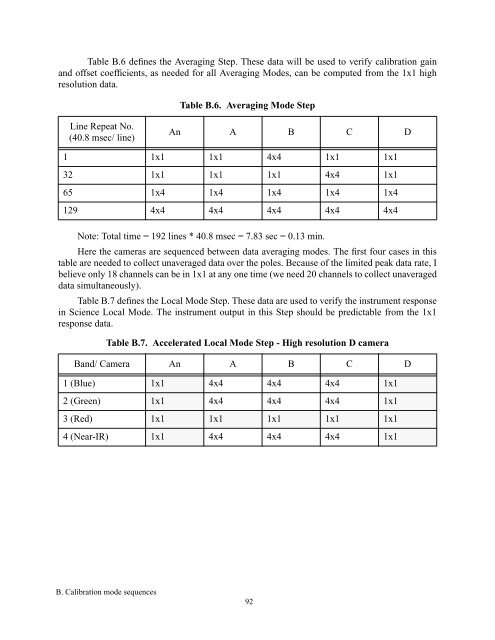
Table B.6 defines the Averaging Step. These data will be used to verify calibration gain<strong>and</strong> offset coefficients, as needed for all Averaging Modes, can be computed from the 1x1 highresolution data.Table B.6. Averaging Mode StepLine Repeat No.(40.8 msec/ line)An A B C D1 1x1 1x1 4x4 1x1 1x132 1x1 1x1 1x1 4x4 1x165 1x4 1x4 1x4 1x4 1x4129 4x4 4x4 4x4 4x4 4x4Note: Total time = 192 lines * 40.8 msec = 7.83 sec = 0.13 min.Here the cameras are sequenced between data averaging modes. The first four cases in thistable are needed to collect unaveraged data over the poles. Because of the limited peak data rate, Ibelieve only 18 channels can be in 1x1 at any one time (we need 20 channels to collect unaverageddata simultaneously).Table B.7 defines the Local Mode Step. These data are used to verify the instrument responsein Science Local Mode. The instrument output in this Step should be predictable from the 1x1response data.Table B.7. Accelerated Local Mode Step - High resolution D cameraB<strong>and</strong>/ Camera An A B C D1 (Blue) 1x1 4x4 4x4 4x4 1x12 (Green) 1x1 4x4 4x4 4x4 1x13 (Red) 1x1 1x1 1x1 1x1 1x14 (Near-IR) 1x1 4x4 4x4 4x4 1x1B. <strong>Calibration</strong> mode sequences92