the download to a suitable location on your local hard disk. Thisis a 6 Mbyte download, so it may take a while.6. Leave your browser and navigate to the directory containingthe Java release you just downloaded. Double-click on thedownload and do a normal install, accepting all defaults. You mayhave to restart your Windows system after installing Java.7. You’re (almost) done: go to the DOS prompt (it is in yourStart menu). Change directories until you find yourself in C:/program files/javasoft/jre/1.2/bin and enter:javayou should see a “Usage” message if everything went well.8. On some Windows releases, the installer will have configuredyour system so it can launch Java applications stored on your harddrive. If not, you may have to set the path variables yourself. Hereis a script I used to test MorsePractice on a Windows/95 system:set PATH=%PATH%;C:\PROGRA~1\JAVASOFT\JRE\1.2\BINset CLASSPATH=%CLASSPATH%;C:\PROGRA~1\JAVASOFT\JRE\1.2\BINecho %PATH%echo %CLASSPATH%The first “set PATH=” commands tells Windows where yourapplications are stored. The second command tells Java where tosearch for the library classes. The two “echo” commands let yousee the current PATH and CLASSPATH settings. Be very carefulwhen you type these commands; make sure they are exactly asshown. If you understand Windows, you should be able to add thePATH and CLASSPATH to your standard configuration.CLASSPATH is specific to Java, and it might not be defined onyour system, so you may need to define it by typing:set CLASSPATH=C:\PROGRA~1\JAVASOFT\JRE\1.2\BINAs you probably know, the Internet changes quickly, so you shouldexpect that the steps may have changed since I wrote this article.Installing MorsePractice on Windows or LinuxAfter you installed Java, you need to dowload Morse-Practice.jar from the ARRL Web site at http://www.arrl.org/files/. Save it to a convenient folder on your hard drive (you maywant to save it to the same directory as the Java.exe file [probablyc:/program files/javasoft/jre/1.2/bin] unless you set up the pathstatements described below). To run it, go to the DOS prompt (orLinux terminal window), set your working directory to thedirectory that holds MorsePractice, and enterjava -cp MorsePractice.jar MainThat’s all: MorsePractice should run in a new window.Windows/95 objects to the long filename. so you will have touse an abbreviated form:java -cp MORSEP~1.jar MainHere’s a complete startup sequence for Windows/95. It assumesthat you installed Java in the standard location and storedMorsePractice.jar in the “Download” folder on your “C:” harddrive. You can edit all of the following into a tiny batch file andrun it all with a single command.set PATH=%PATH%;C:\PROGRA~1\JAVASOFT\JRE\1.2\BINset CLASSPATH = % CLASSPATH %; C:\ PROGRA~1\JAVASOFT\JRE\1.2\BINcd C:\Downloadjava -cp MORSEP~1.jar MainMorse Code Links On The WebIf you’re interested in Morse code, you may find these linksuseful…50 <strong>May</strong> <strong>2000</strong>• The ARRL Web Morse page at: http://www.arrl.org/ead/learncw/• The Art and Skill of Radio Telegraphy by William G. Pierpoint,N0HFF: http://www.joates.demon.co.uk/megs/N0HFF/index.htm• MEGS is a group of radio amateurs and shortwave listenersinterested in Morse code: http://www.joates.demon.co.uk/megs/• So You Want to Learn Morse Code by David G. Finley hasinformation on Morse code training, including links to his book,Morse Code, Breaking the Barrier and information on using theKoch Method with the SuperMorse software package:http://griffy.nmt.edu/sara/sara/finley.morse.htmlhttp://www.sdc.org/%7Efinley/http://griffy.nmt.edu/sara/sara/finley.sm404.html• The Victorian Internet is an interesting book on the developmentof telegraphy in the 1800s. Also, the article on the telegraph in the11th edition of the Encyclopedia Brittanica is well worth reading.[The author upgraded to General on March 18, <strong>2000</strong>. He givesmuch of the credit to Morsepractice!—Ed]332 Molimo DrSan Francisco, CA 94127-1620k6mam@arrl.netNEW PRODUCTSHF BAND-PASS FILTERS FROM ARRAY SOLUTIONS◊ The WX0B BPF-1 is an integratedset of 6 HF band-passfilters housed in a single enclosure.This new filter system isdesigned to reduce the harmonicenergy and wideband phasenoise generated by transmittersand to limit the receiver desensingthat is common whenmultiple HF stations are operatedin proximity.Possible applications includethe reduction of cross band interferencein single operator two radio, multi-single and multi-multi(ie Field Day) contest operations; for multi transmitter DXpeditions;and for monitoring facilities that may have the need totransmit on one band of frequencies while listening on another.The BPF-1 contains 6 filters for 10, 15, 20, 40, 80 and 160meters. Custom-built units are available for alternative frequencyranges. The desired band filter can be selected automatically usingexternal band data information, or manually using an optionalremote manual selector switch box. A bypass mode is included andwill engage automatically if dc power is disconnected.The enclosure dimensions are 7 × 14.25 × 3 inches, SO-239 typeconnectors are used for the input and output and a 7-section terminalstrip mounted on an internal PC board provides a connectionpoint for the external switching source.Claimed specifications include 200 W CW/RTTY/SSB powerhandling capability (at an SWR
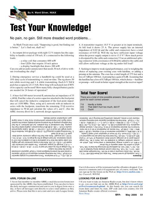
By H. Ward Silver, N0AXTest Your Knowledge!No pain, no gain. Still more dreaded word problems…As Mark Twain once said, “Supposing is good, but finding outis better.” Let’s find out, shall we?1. An output driver package with eight 12-V outputs has the capabilityto handle a total of 150 mA. It’s connected to the followingloads:- a relay coil that consumes 600 mW- four LEDs that require 10 mA apiece- a display backlight that draws 200 mWCan you add an audio annunciator that needs 30 mA of drive withoutoverloading the chip?2. During emergency service a handheld rig could be used at a10% duty cycle of transmitting vs. total on-time. The rig draws 50mA while receiving and 1 A while transmitting. Each 8-V NiCdpack has a capacity of 2.5 A/h. How long will each pack last if 80%of its capacity can be used? How many fully-charged battery packsare needed for 24 hours of operation?3. A base-fed 160-meter inverted-L antenna has an impedance of 35+ j40 Ω. Find the value of a series capacitor attached to the feed pointthat will cancel the inductive component of the feed point impedanceat 1.830 MHz. Then, using an L-network with an inductor inseries with the feedpoint, transform the remaining 35 Ω resistiveimpedance to 50 Ω and calculate the values of L and C. (See theARRL Antenna Book for L-network design equations.)4. A transmitter requires 10.5 V or greater at its input terminals.At full load it draws 25 A. The power supply has an internalimpedance of 0.02 Ω and the cable and connectors have a totalresistance of 0.05 Ω. Will the rig have sufficient input voltagewhen the power supply output is set to 13.5 V? How much poweris dissipated by the cable and connectors? Can an additional splicingconnector with a resistance of 0.06 Ω be added to the cable andstill allow sufficient voltage at the rig under full load?5. Seeking to improve weak signal performance, you’re weighing thechoice of replacing your existing coax with hardline, or adding apreamp at the antenna. The coax has a total length of 275 feet and aloss of 3 dB per 100 feet. A preamp has a gain of 6 dB. Assuming thatthe hardline has a loss of 0.5 dB per 100 feet, which choice —hardlineor preamp—will result in better signal strength at the receiver input?Total Your Score!There are a total of nine possible answers. Give yourself onepoint for each correct answer.7-9 Hardly a tickle4-6 That didn’t hurt too much, did it?1-3 Ouch!of -40 + 23 = -17 Ω of reactance. This is equivalent to a single capacitorof 5120 pF. Thus, the matching network reduces to a 5120 pF capacitorin series with the antenna feedpoint and a 1133 pF capacitor connectedacross the feed line output.4. The voltage at the rig under full load is 13.5 V – 25 A × (0.02 + 0.05 Ω)= 11.8 V; enough for proper operation. The cables and connector dissipate25 2 × 0.05 = 31.3 W. Note that a loose connector can get mightyhot under loads like this! If an additional 0.06 Ω is added to the 0.07 Ωseries resistance, full load voltage at the rig drops to 13.5 – 25 (0.13) =10.3V—not enough! Note also that this single connector would dissipate37.5 W all by itself.5. The existing cable is causing 275 × 3/100 = 8.25 dB loss. Hardline of thesame length will result in 275 × 0.5/100 = 1.38 dB. Cable replacementresults in 8.25 – 1.38 = 6.88 dB of improvement, slightly better than thepreamp. Not considered in this problem, but still pertinent, is the factthat adding a preamp at the antenna would probably reduce the systemnoise figure and improvement performance more than a mere signalgain computation would indicate.Answers1. First, compute all current draws. The relay coil draws 600 mW / 12 V =50 mA. The LEDs consume a total of 40 mA. The backlight draws 200mW / 12 V = 16.7 mA. The total current already being handled is 50 +40 + 16.7 = 106.7 mA. An additional 30 mA brings the total to 136.7 mA,which is within the rated capacity of the driver.2. If 80% of a pack’s energy (expressed in amp-hours (Ah), which assumesconstant voltage) is available for use, that’s 2 Ah. The usageprofile given is an average current drain consisting of 10% at 1 A plus90% at 0.05 A = 145 mA. The total time this load can be supported is 2/ 0.145 = 13.8 hours. For 24 hours of operation you’ll need 2 packs.3. At 1.830 MHz, a capacitive reactance of 40 Ω requires 1/(6.28 ×1.830MHz × 40) = 2180 pF. This leaves an impedance of 35 Ω to be transformedto the desired impedance of 50 Ω. From the L-network designequations, Q is calculated to 0.66; XL = 0.66 × 35 = 23 Ω; X C = 50 / 0.66= 75 Ω; L = 23 / (1.83 MHz × 6.28) = 2 µH; C = 1 / (1.83 MHz × 6.28 ×75) = 1133 pF. Note that the feedpoint capacitor and matching networkinductor are in series, partially cancelling and leaving a net reactanceSTRAYSARRL FORUM ON-LINE◊ An on-line member-to-member ARRL e-mail discussion forum (notsponsored by the ARRL) has been established. You can elect to havethe daily messages summarized and sent to you in digest form once aday, or have all messages sent directly to your e-mail address as theyarrive. Please note that this is not a rant-and-rave anti-League forum.Uncivil discourse will be terminated and the offenders dropped. Constructivecomments and civil arguments are, of course, welcome. Youcan sign up for the forum on the Web at: http://www.onelist.com.—Jay Craswell, W0VNELOOKING FOR AN EXAM?◊ If you want to take an Amateur Radio exam, but don’t know whereto go, you can find out on the ARRLWeb at http://www.arrl.org/arrlvec/examsearch.phtml. At this handy site you can search forexam dates and times by state, ZIP code and even country (for USAmateur Radio exams offered overseas).Next Stray<strong>May</strong> <strong>2000</strong> 51
- Page 6 and 7: May 2000 Volume 84 Number 5David S
- Page 11 and 12: THE AMERICAN RADIORELAY LEAGUE INC
- Page 14: Get to Know Your Section ManagerThe
- Page 18: The ARRL and the FCC’s Private Wi
- Page 22 and 23: The postman always keys twice.Accor
- Page 26 and 27: CORRESPONDENCEYour opinions count!
- Page 30 and 31: By Ian Poole, G3YWXOperating in the
- Page 32 and 33: By Roger Sullivan, WA0ETE, and Hugh
- Page 34 and 35: By Jim Graver, KB8PSO2000Dayton Ham
- Page 36 and 37: Figure 1A—Schematic of the interf
- Page 38 and 39: All input/output connections are ma
- Page 40 and 41: Figure 4—Hanger loopconstruction.
- Page 42 and 43: Figure 2—A GOES-8 picture capture
- Page 44 and 45: By Steve Ford, WB8IMYPSK31 2000In e
- Page 46 and 47: the software, PSK31 tuning required
- Page 48 and 49: WORKBENCHPROJECTS AND INFORMATION F
- Page 50 and 51: By Martin A. Minow, K6MAMPractice M
- Page 54 and 55: 52 May 2000SHORT TAKESHeil Sound Go
- Page 56 and 57: By Zack Lau, W1VTA No-Tune 2-Meter
- Page 58 and 59: HINTS & KINKSA FOLD-DOWN MOBILE-ANT
- Page 60 and 61: By James Kates, N9GBBConfessions of
- Page 62 and 63: PRODUCT REVIEWKenwood TM-D700A Dual
- Page 64 and 65: is accomplished by using OK, BACK a
- Page 66 and 67: other radio operation. The chatter
- Page 68 and 69: operation because there’s so litt
- Page 70 and 71: consideration in the WT Docket 98-1
- Page 72 and 73: News in Brief:• League members no
- Page 74 and 75: communications tests in celebration
- Page 76 and 77: I’ve done this tour several years
- Page 78 and 79: The Crystal Symphony at anchor off
- Page 80 and 81: Table 1Claimed North American Dista
- Page 82 and 83: Okay in My LogBy Vic Curtis,WA3YUVP
- Page 84 and 85: their 432 MHz triumph of the previo
- Page 86 and 87: 2000 ARRL Field DayRulesBy Dan Hend
- Page 88 and 89: Collecting Vintage QSLsOLD RADIOAn
- Page 90 and 91: DIGITAL DIMENSIONAPRS Digipeater in
- Page 92 and 93: AT THE FOUNDATIONWhy We Fund Museum
- Page 94 and 95: It is with deep regret that we reco
- Page 96 and 97: COMING CONVENTIONSARRL NATIONAL CON
- Page 98 and 99: checking; handicapped accessible; f
- Page 106:
of the West Allis ARC and served as
- Page 110:
introduced that could of had a bear
- Page 114:
211/109; NJN/L 29/203/103; CJTN 29/
- Page 118:
W1PEX 1048, WA1JVV 143, N1NH 105, W
- Page 124:
an activity we enjoy so much can be
- Page 128:
126He is President of the Amateur R
- Page 132:
is Walt Bacon, N6SMT, who is curren
- Page 150:
Ham Adsl) Advertising must pertain
- Page 154:
BAHAMAS RENTAL: Abaco villa w/stati
- Page 164:
“EVERYTHING FOR THE MORSE ENTHUSI
- Page 168:
TUBES WANTED: Highest prices paid o


