
You also want an ePaper? Increase the reach of your titles
YUMPU automatically turns print PDFs into web optimized ePapers that Google loves.
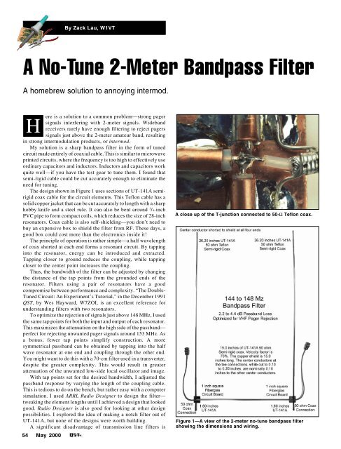
By Zack Lau, W1VTA No-Tune 2-Meter Bandpass FilterA homebrew solution to annoying intermod.ere is a solution to a common problem—strong pagerHsignals interfering with 2-meter signals. Widebandreceivers rarely have enough filtering to reject pagerssignals just above the 2-meter amateur band, resultingin strong intermodulation products, or intermod.My solution is a sharp bandpass filter in the form of tunedcircuit made entirely of coaxial cable. This is similar to microwaveprinted circuits, where the frequency is too high to effectively useordinary capacitors and inductors. Inductors and capacitors workquite well—if you have the test gear to tune them. I found thatsemi-rigid cable could be cut accurately enough to eliminate theneed for tuning.The design shown in Figure 1 uses sections of UT-141A semirigidcoax cable for the circuit elements. This Teflon cable has asolid copper jacket that can be cut accurately to length with a sharphobby knife and a steel rule. It can also be bent around 3 /4-inchPVC pipe to form compact coils, which reduces the size of 28-inchresonators. Coax cable is also self-shielding—you don’t need tobuy an expensive box to shield the filter from RF. These days, agood box could cost more than the electronics inside it!The principle of operation is rather simple—a half wavelengthof coax shorted at each end forms a resonant circuit. By tappinginto the resonator, energy can be introduced and extracted.Tapping closer to ground reduces the coupling, while tappingcloser to the center point increases the coupling.Thus, the bandwidth of the filter can be adjusted by changingthe distance of the tap points from the grounded ends of theresonator. Filters using a pair of resonators have a goodcompromise between performance and complexity. “The Double-Tuned Circuit: An Experiment’s Tutorial,” in the December 1991<strong>QST</strong>, by Wes Hayward, W7ZOI, is an excellent reference forunderstanding filters with two resonators.To optimize the rejection of signals just above 148 MHz, I usedthe same tap points for both the input and output of each resonator.This maximizes the attenuation on the high side of the passband—perfect for rejecting unwanted pager signals around 153 MHz. Asa bonus, fewer tap points simplify construction. A moresymmetrical passband can be obtained by tapping into the halfwave resonator at one end and coupling through the other end.You might want to do this with a 70-cm filter used in a transverter,despite the greater complexity. This would result in greaterattenuation of the unwanted low-side local oscillator and image.With tap points set for the desired bandwidth, I adjusted thepassband response by varying the length of the coupling cable.This is tedious to do on the bench, but rather easy with a computersimulation. I used ARRL Radio Designer to design the filter—tweaking the element lengths until I achieved a design that lookedgood. Radio Designer is also good for looking at other designpossibilities. I explored the idea of making a notch filter out ofUT-141A, but none of the designs were worth building.A significant disadvantage of transmission line filters is54 <strong>May</strong> <strong>2000</strong>A close up of the T-junction connected to 50-Ω Teflon coax.Figure 1—A view of the 2-meter no-tune bandpass filtershowing the dimensions and wiring.