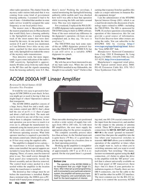
other radio operation. The chatter from themystery radio station indicated that it wascoming from some kind of governmenthousing authority. I assumed it had to beout of state—I doubted that another in-stateradio service would be assigned the samefrequency as our local police force.The nearest state is Massachusetts andthe nearest populated area in Massachusettsthat would likely have a housing authorityis the Springfield area. I started keepingtrack of the street names that were mentionedby the users. At one point, the intersectionof X and Y streets was mentioned,so I ran Delorme Street Atlas on my computer,searched for that street intersectionand, voilá, Springfield was indeed the sourceof the mystery radio transmissions.Nice detective work, but more importantlyit gave some indication of the radio’sUHF sensitivity. Springfield is approximately40 miles away from my radio shackas the RF flies and the signals emanatingfrom the housing authority were S-9. But,there’s more! Pushing the envelope, Istarted monitoring the Springfield housingauthority while mobile and I was shockedhow well I was able to hear that operationwhile traversing the hills and dales aroundtown. This was very impressive!For a weekend, I replaced the WA1LOU-15 APRS digipeater radio equipment with theTM-D700A using its built-in APRS software.None of the users noticed any difference inthe digipeater’s operation. (At least, no onecomplained and, as they say, “No news isgood news.”)The TM-D700A may lack some stateof-the-artAPRS digipeater protocol featureslike TRACE N-N and WIDE N-N, butit can still serve as a suitable APRSdigipeater in a pinch.The Ultimate TestMy wife has never been interested in anyof my ham radio toys. When she saw theTM-D700A installed in my Oldsmobile, shethought it was actually “neat!” I believe thatearning that response from her qualifies thisradio as a major milestone in Amateur Radioequipment design!I am the administrator of the HTAPRSSpecial Interest Group (SIG), which is ane-mail list devoted to the discussion of technologytopics related to APRS—includingthe TM-D700A. The SIG is sponsored byTAPR. If you have questions concerning theoperation of this transceiver, this list canprovide a good source of information.You’ll also discover how other owners areusing the radio. You can subscribe to theHTAPRS SIG by visiting http://www.tapr.org/tapr/html/sigf.html. Selectthe “Join APRS HT” link.Manufacturer: Kenwood CommunicationsCorp, 2201 E Dominguez St, LongBeach, CA 90801; 310-639-5300; fax 310-537-8235; http://www.kenwood.net.Manufacturer’s suggested retail price,$780. Typical current street price, $660.PG-4X Extension Cable Kit, $70; VS-3Voice Synthesizer Unit, $40.ACOM <strong>2000</strong>A HF Linear AmplifierReviewed by David Sumner, K1ZZExecutive Vice PresidentIt would be very easy to get used to havingan ACOM <strong>2000</strong>A in your shack. In fact,you might get so used to having it that youmight forget it’s there! Operation is almostthat transparent.The ACOM <strong>2000</strong>A amplifier consists ofa large, heavy, black box and a small, separateremote control unit (RCU) that’s abouthalf the size of an 8 1 /2 × 11 sheet of paperand about a half-inch thick. The main unitcan be stowed in any out-of-the-way cornerwhere there is adequate ventilation. In normaloperation you never have to touch it oreven see it, although the manufacturer recommendsusing the master power switch (theblack box’s only control) to turn the poweroff between operating sessions. What littleoperator interface is required is provided bythe remote control unit, which can be as muchas 10 feet away using the supplied cable.The amplifier is shipped in two cartons—the transformer is boxed separately. Thetubes come installed, but special supports areincluded to keep them from shifting duringshipping. These, of course, must be removedprior to use. Two small screws through theback panel also temporarily secure theblower assembly and are likewise removed.The control head comes packed in a boxnestled within the amplifier in the locationwhere the transformer is installed.The desired ac line voltage must be setbefore the transformer is installed. Ratherthan a terminal strip, the <strong>2000</strong>A uses a PCboardwith 9 metal posts arranged in a grid.64 <strong>May</strong> <strong>2000</strong>Bottom LineThe operation of the ACOM <strong>2000</strong>A isso transparent that you might forget it’sthere. After initial set up and programmingwith it connected to your particular antennasystem, the amplifier will sense your transmittingfrequency and automatically tuneitself for the band segment of interest.Three movable shorting bars are positionedto allow a wide variety of supply line voltagesfrom 100 to 240 volts. As with mostHF amplifiers, the user must supply theappropriate plug for the power receptacle.The complete assembly process takesless than an hour. As the finished main unitis quite heavy (79 lbs), it’s a good idea toput the amp together in a location close toits final operating position.Hooking up the amplifier is straightforward.For full-power operation, a sourceof approximately 240 V ac at 20 A is required.On the rear panel there’s a groundingstud, one SO-239 coaxial connector forthe input from the transceiver, and anotherfor the output to the antenna or antennaswitch. Three RCA phono jacks provideconnections for KEY IN, KEY OUT and ALC.KEY IN is the usual “ground on transmit”control line that puts the amplifier into theline when your transceiver switches totransmit. KEY OUT allows you to inhibit theoperation of the amplifier at times whenyou might want to, such as when you’reswitching antennas and you want to avoidinadvertently “hot switching.” The manufacturerrecommends against using the ALCconnection—it’s better to adjust the driveto the amplifier with the “RF power” controlthat is almost universally available onthe front panel of HF transceivers thesedays—but it’s there if your particular installationrequires it. Finally, there are twoDB-9 connectors, one for the cable to theRCU and the other for an RS-232 interface.The most common use for the RS-232 interfaceis to control the accessory ACOM
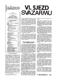
Figure 2—The optional weatherproof <strong>2000</strong>SW10-position remote antenna switch and thecorresponding <strong>2000</strong>S automatic antennaselector control.0–10–20–30–40–50–60–70Reference Level: 0 dB PEPTable 2ACOM <strong>2000</strong>A, serial number 990346Manufacturer’s Claimed SpecificationsFrequency Range (US units): All amateurfrequencies, 1.8 to 29.7 MHz. 1Power output: 1500 W PEP, all modesand continuous or modulated carrier. 2Driving power required: 50 to 60 W.Input SWR: less than 1.3:1Output matching: up to 3:1 SWR(2:1 for 160 meters).<strong>2000</strong>S automatic antenna selector and<strong>2000</strong>SW remote antenna switch; we’ll havemore to say about these accessories later.When you turn the amplifier on (usingthe rocker switch on the front panel and thedistinctive red POWER ON/OFF pushbuttonon the RCU) the LCD display on the RCUcomes to life and it beeps a cheery “TEST”in Morse code. The fan also turns on, althoughif you have a desktop PC runningin the shack you may not notice it; it’s quieterthan many PCs. It takes 2 1 /2 minutesfor the pair of 4CX800A tubes to warm up,during which time a countdown clock onthe RCU tells you how many seconds youhave to wait. A Morse “R” tells you whenthe amplifier is ready. Push OPR/STB toswitch from Standby and you’re ready togo. In addition to the LCD display the RCUhas peak-reading LED bar displays showingforward and reflected power and individualLEDs to show when power is on andwhether the amplifier is operational or instandby, and to warn of abnormal operation.The first time you use the amplifier witha particular antenna or on a particular bandsegment (the amateur HF bands are dividedinto 40 different band segments ranging inwidth from 25 kHz in the 160-meter band to300 kHz in the 10-meter band) you will haveto run through a simple autotune procedure.Measured in ARRL LabAs specified.As specified for SSB and CW.As specified.As specified.As specified.Spurious signal and harmonic50 dB, worst case (3.5 MHz).suppression: 50 dB below rated outputor greater.Intermodulation distortion (IMD): –35 dB. See Figure 1.Primary power requirements: 90-132, 180-264 V ac (five user settable taps).Size (hwd): 7.1×17.3×19.7 inches; weight, 79 lb.An expanded test result report for this amplifier is available on the ARRL Members-Only Web site. Printed copies are also available for those without Web access.11.8-21.7 MHz. Frequencies above 21.7 MHz can be unblocked with proof of proper licensing.2Optional auxiliary cooling fan recommended for extended high-duty-cycle operation.–80–10 –8 –6 –4 –2 0 2 4 6 8 10Frequency Offset (kHz)Figure 1—The spectral display of theACOM <strong>2000</strong>A during two-tone intermodulationdistortion (IMD) testing on14 MHz at 1500 W PEP output. The thirdorderproduct is approximately 37 dBbelow PEP output, and the fifth-orderproduct is down approximately 60 dB.Push ENT twice and the LCD display will tellyou to apply 10-20 W of drive. The displaywill show you when the drive is within theselimits. As soon as it is, the autotune circuitrywill take over and a second or so later themessage “AUTOTUNE COMPLETEDPLEASE REMOVE DRIVE” will appear onthe LCD. That’s all there is to it! From thatpoint on, the amplifier will automaticallysense (from the first few milliseconds of driveyou apply to the input) the operating frequencyand will tune itself up for that bandsegment. Manual tuning is also possible, butit’s unlikely you would ever need to resort toit in normal operating. The amplifier requiresabout 60 W of drive to deliver the full legallimitoutput of 1500 W.The amplifier can handle VSWRs of upto 3:1 on all bands except 160 meters,where the limit is 2:1. Should the characteristicsof your antenna change drastically,either through failure of the antenna orfeedline or because of temporary weatherconditions such as icing, the amplifier willsense the change and will put itself instandby, displaying an appropriate errormessage. The same thing will happen if youapply too much drive or commit some other“cockpit error.” While any high-powertransmitter is worthy of the utmost care andrespect, it would be very difficult to damagethis amplifier through inadvertence.The LCD display normally shows thetemperature of the exhaust air, whether theamplifier is in Standby or Operate, the bandsegment and antenna (if the automatic antennaselector is installed) that are in use,and whether the amplifier is tuned to factorydefault or user-defined settings. Thereare 20 other operating parameters that canbe measured and displayed, two at a time,by digital readout. You can check yourpower line voltage, plate voltage and current,antenna VSWR, drive power, and a hostof others—even the power gain of the amplifier!Monitoring some of these parametersduring CW or SSB operation isn’t possiblebecause they change too quickly, but a briefkey-down test (into a dummy load, please!)will tell you what you need to know.ACOM encourages amateurs who buythe <strong>2000</strong>A also to pick up the <strong>2000</strong>S automaticantenna selector and <strong>2000</strong>SW 10-position remote antenna switch (see Figure2). Once you have used them together it’seasy to see why. The amplifier will automaticallyselect the last antenna that wasused in the band segment of operation.Changing bands becomes a matter of choosingyour operating frequency on yourtransceiver, tapping your key or your microphone,and waiting for the second or sothat it takes for the amplifier to sense thenew operating frequency, tune itself to thatfrequency, and select the right antenna.Alternatively, you can use the computer interfaceto the <strong>2000</strong>S and the switch will followcommands from the computer ratherthan from the amplifier. If you have morethan one antenna per band you can selectthem (up to a maximum of 10) using the<strong>2000</strong>S control box or your own switchingsystem. If the antennas tune differently,don’t worry—the amplifier will rememberseparate settings for up to 10 antennas perband segment!It’s difficult to describe the <strong>2000</strong>A in<strong>May</strong> <strong>2000</strong> 65
- Page 6 and 7:
May 2000 Volume 84 Number 5David S
- Page 11 and 12:
THE AMERICAN RADIORELAY LEAGUE INC
- Page 14:
Get to Know Your Section ManagerThe
- Page 18: The ARRL and the FCC’s Private Wi
- Page 22 and 23: The postman always keys twice.Accor
- Page 26 and 27: CORRESPONDENCEYour opinions count!
- Page 30 and 31: By Ian Poole, G3YWXOperating in the
- Page 32 and 33: By Roger Sullivan, WA0ETE, and Hugh
- Page 34 and 35: By Jim Graver, KB8PSO2000Dayton Ham
- Page 36 and 37: Figure 1A—Schematic of the interf
- Page 38 and 39: All input/output connections are ma
- Page 40 and 41: Figure 4—Hanger loopconstruction.
- Page 42 and 43: Figure 2—A GOES-8 picture capture
- Page 44 and 45: By Steve Ford, WB8IMYPSK31 2000In e
- Page 46 and 47: the software, PSK31 tuning required
- Page 48 and 49: WORKBENCHPROJECTS AND INFORMATION F
- Page 50 and 51: By Martin A. Minow, K6MAMPractice M
- Page 52 and 53: the download to a suitable location
- Page 54 and 55: 52 May 2000SHORT TAKESHeil Sound Go
- Page 56 and 57: By Zack Lau, W1VTA No-Tune 2-Meter
- Page 58 and 59: HINTS & KINKSA FOLD-DOWN MOBILE-ANT
- Page 60 and 61: By James Kates, N9GBBConfessions of
- Page 62 and 63: PRODUCT REVIEWKenwood TM-D700A Dual
- Page 64 and 65: is accomplished by using OK, BACK a
- Page 68 and 69: operation because there’s so litt
- Page 70 and 71: consideration in the WT Docket 98-1
- Page 72 and 73: News in Brief:• League members no
- Page 74 and 75: communications tests in celebration
- Page 76 and 77: I’ve done this tour several years
- Page 78 and 79: The Crystal Symphony at anchor off
- Page 80 and 81: Table 1Claimed North American Dista
- Page 82 and 83: Okay in My LogBy Vic Curtis,WA3YUVP
- Page 84 and 85: their 432 MHz triumph of the previo
- Page 86 and 87: 2000 ARRL Field DayRulesBy Dan Hend
- Page 88 and 89: Collecting Vintage QSLsOLD RADIOAn
- Page 90 and 91: DIGITAL DIMENSIONAPRS Digipeater in
- Page 92 and 93: AT THE FOUNDATIONWhy We Fund Museum
- Page 94 and 95: It is with deep regret that we reco
- Page 96 and 97: COMING CONVENTIONSARRL NATIONAL CON
- Page 98 and 99: checking; handicapped accessible; f
- Page 106: of the West Allis ARC and served as
- Page 110: introduced that could of had a bear
- Page 114: 211/109; NJN/L 29/203/103; CJTN 29/
- Page 118:
W1PEX 1048, WA1JVV 143, N1NH 105, W
- Page 124:
an activity we enjoy so much can be
- Page 128:
126He is President of the Amateur R
- Page 132:
is Walt Bacon, N6SMT, who is curren
- Page 150:
Ham Adsl) Advertising must pertain
- Page 154:
BAHAMAS RENTAL: Abaco villa w/stati
- Page 164:
“EVERYTHING FOR THE MORSE ENTHUSI
- Page 168:
TUBES WANTED: Highest prices paid o