Introduction
Introduction
Introduction

You also want an ePaper? Increase the reach of your titles
YUMPU automatically turns print PDFs into web optimized ePapers that Google loves.
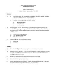
1/23/2011Example:-a) For an op amp, define the following termsi) Offset currentii) Common mode rejection ratiob) State the functions of pins 1, 2 and 4 of timer 555 is operated in amonostable modec) A 555 timer circuit is connected in astable mode with the values of thefollowing components: -R A = 2k, R B = 4k and C = 0.1μF. Calculate,T H , T L and T, frequency, f, Percentage of duty cycle, %DT. Draw the outputwaveform.Januari 2009a) Draw and label a complete symbol of the op-amp.b) Give FOUR (4) differences between ideal characteristics andactual characteristics of the op-ampc) i. Sketch the waveform on pin 2 and pin 3 of timer 555 when it isoperated in the astable mode.ii. A 555 timer connected in the unstable mode and given R A = 2.3k,R B = 4.6k and C = 0.1μF. Calculate T H , T L , frequency, f andpercentage of duty cycle of output waveform.Januari 201035