Uranium ore-forming systems of the - Geoscience Australia
Uranium ore-forming systems of the - Geoscience Australia
Uranium ore-forming systems of the - Geoscience Australia

Create successful ePaper yourself
Turn your PDF publications into a flip-book with our unique Google optimized e-Paper software.
G E O S C I E N C E A U S T R A L I A<strong>Uranium</strong> <strong>ore</strong>-<strong>forming</strong> <strong>systems</strong> <strong>of</strong> <strong>the</strong>Lake Frome region, South <strong>Australia</strong>:Regional spatial controls and exploration criteriaRoger G. Skirrow (editor)Record2009/40GeoCat #69697APPLYING GEOSCIENCE TO AUSTR ALIA’S MOST IMPORTANT CHALLENGES
Department <strong>of</strong> Resources, Energy and TourismMinister for Resources and Energy: The Hon. Martin Ferguson, AM MPSecretary: John Pierce<strong>Geoscience</strong> <strong>Australia</strong>Chief Executive Officer: Dr Neil Williams PSM© Commonwealth <strong>of</strong> <strong>Australia</strong>, 2009This work is copyright. Apart from any fair dealings for <strong>the</strong> purpose <strong>of</strong> study, research, criticism,or review, as permitted under <strong>the</strong> Copyright Act 1968, no part may be reproduced by any processwithout written permission. Copyright is <strong>the</strong> responsibility <strong>of</strong> <strong>the</strong> Chief Executive Officer,<strong>Geoscience</strong> <strong>Australia</strong>. Requests and enquiries should be directed to <strong>the</strong> Chief Executive Officer,<strong>Geoscience</strong> <strong>Australia</strong>, GPO Box 378 Canberra ACT 2601.<strong>Geoscience</strong> <strong>Australia</strong> has tried to make <strong>the</strong> information in this product as accurate as possible.However, it does not guarantee that <strong>the</strong> information is totally accurate or complete. Theref<strong>ore</strong>, youshould not solely rely on this information when making a commercial decision.ISSN 1448-2177ISBN 978-1-921672-39-2 printISBN 978-1-921672-37-8 webGeoCat # 69697Bibliographic reference:To cite <strong>the</strong> entire <strong>Geoscience</strong> <strong>Australia</strong> Record:Skirrow, R.G., 2009 (editor). <strong>Uranium</strong> <strong>ore</strong>-<strong>forming</strong> <strong>systems</strong> <strong>of</strong> <strong>the</strong> Lake Frome region, South<strong>Australia</strong>: Regional spatial controls and exploration criteria. <strong>Geoscience</strong> <strong>Australia</strong> Record 2009/40,151 p.To cite individual chapters in <strong>the</strong> Record, e.g.:van der Wielen, S., Britt, A., and Skirrow, R.G., 2009. Chapter 3. 3D architecture and permeability.In Skirrow, R.G. (ed.), <strong>Uranium</strong> <strong>ore</strong>-<strong>forming</strong> <strong>systems</strong> <strong>of</strong> <strong>the</strong> Lake Frome region, South <strong>Australia</strong>:Regional spatial controls and exploration criteria. <strong>Geoscience</strong> <strong>Australia</strong> Record 2009/40, p. 20-42.
<strong>Uranium</strong> <strong>ore</strong>-<strong>forming</strong> <strong>systems</strong> <strong>of</strong> <strong>the</strong> Lake Frome region7.2.1 Objectives <strong>of</strong> <strong>the</strong> study .................................................................................................807.2.2 Geological constraints ..................................................................................................807.2.3 Building simplified 2D geological models for fluid flow modelling ..........................847.2.4 Representation <strong>of</strong> results – fluid flow modelling ........................................................857.3 Results and discussion – fluid flow modelling ....................................................................867.3.1 Fluid flow scenarios in <strong>the</strong> Beverley – Four Mile district ...........................................867.3.2 <strong>Uranium</strong> mass balance calculations – Four Mile East deposit ....................................887.4 Geochemical modelling <strong>of</strong> Frome uranium <strong>systems</strong>............................................................967.4.1 Methodology and model setup ....................................................................................967.4.2 Granite-water interaction (modelling Paralana Hot Springs) ......................................977.4.3 Modelling granite-water-sandstone interaction (formation <strong>of</strong> sandstone-hosteduranium mineralisation)..............................................................................................................997.4.4 Summary <strong>of</strong> geochemical modelling results..............................................................1007.5 Conclusions – numerical modelling...................................................................................1018. Syn<strong>the</strong>sis, and implications for exploration.................................................................................1028.1 Essential components <strong>of</strong> basin-related uranium mineral <strong>systems</strong> <strong>of</strong> <strong>the</strong> Lake Frome region..................................................................................................................................................1028.1.1 Sources <strong>of</strong> <strong>ore</strong> constituents and fluids .......................................................................1028.1.2 Energy and timing .....................................................................................................1048.1.3 Permeability architecture and fluid flow ...................................................................1048.1.4 Depositional gradients for uranium mineralisation ...................................................1078.2 Paleogeographic and uranium mineral system evolution...................................................1088.3 Exploration criteria ............................................................................................................1118.3 Recommendations for fur<strong>the</strong>r work ...................................................................................111References.........................................................................................................................................114Appendix 1: Field guide to <strong>the</strong> Proterozoic Mt Painter Inlier and Mesozoic to Cenozoic basins <strong>of</strong> <strong>the</strong>Lake Frome region....................................................................................................................120Appendix 2: Metadata for 3D geological maps, Figures 3.3-3.7. ....................................................140Page iv <strong>of</strong> 151
<strong>Uranium</strong> <strong>ore</strong>-<strong>forming</strong> <strong>systems</strong> <strong>of</strong> <strong>the</strong> Lake Frome regionAbstractCenozoic basins <strong>of</strong> <strong>the</strong> Lake Frome region in South <strong>Australia</strong> contain most <strong>of</strong> <strong>the</strong> nation’s knownresources <strong>of</strong> sandstone-hosted uranium mineralisation. In addition to <strong>the</strong> currently operatingBeverley uranium mine, two o<strong>the</strong>r deposits have been approved for mining (Honeymoon, FourMile East), and discoveries continue to be made in <strong>the</strong> region (e.g., Pepegoona; HeathgateResources, announcement September 2009). While <strong>the</strong> known resources are significant, <strong>the</strong>potential <strong>of</strong> <strong>the</strong> region for very large uranium deposits has not been well understood, in part due tolimited knowledge <strong>of</strong> <strong>the</strong> regional- and district-scale geological controls on uraniummineralisation.The multidisciplinary study reported herein applies a ‘mineral <strong>systems</strong>’ approach to identify andmap <strong>the</strong> principal geological controls on <strong>the</strong> location <strong>of</strong> known uranium mineralisation in <strong>the</strong> LakeFrome region. This new framework is aimed at providing a basis for refined exploration targeting<strong>of</strong> areas with potential for major undiscovered deposits, thus reducing risk in investment by <strong>the</strong>exploration industry.Mineral <strong>systems</strong> approach – Major <strong>ore</strong> deposits are <strong>the</strong> product <strong>of</strong> crustal- to deposit- to microscalegeological processes, and require <strong>the</strong> presence <strong>of</strong> (a) suitable sources <strong>of</strong> metals, fluids(aqueous, magmas, etc), ligands (for hydro<strong>the</strong>rmal deposits), sulfur (for sulfide deposits), (b)permeable pathways or permeability architecture for transport <strong>of</strong> metals and for focussing andoutflow <strong>of</strong> fluids, (c) energy sources to drive <strong>the</strong> <strong>ore</strong>-<strong>forming</strong> system, and (d) chemical and/orphysical depositional gradients where <strong>the</strong> <strong>ore</strong> metals are precipitated. Suitable sources,permeability architecture, and physico-chemical gradients occur only in specific ‘fertile’ terranesthat have experienced favourable geodynamic and tectonic evolution, and where <strong>the</strong> sequence <strong>of</strong>geological events permits an efficient physical link (permeability architecture) between <strong>the</strong>sources regions and <strong>the</strong> <strong>ore</strong> depositional environments. The present study aims to identify and map<strong>the</strong> geological ‘proxies’ (i.e., observable geological features) for each <strong>of</strong> <strong>the</strong> four mineral systemcomponents. In addition, successful exploration for major uranium or o<strong>the</strong>r deposits requires that<strong>the</strong> deposits are preserved at depths accessible to exploration methods.Sources <strong>of</strong> U, fluids, ligands – It is widely assumed <strong>the</strong> uranium was sourced from <strong>the</strong> uraniumrichProterozoic basement in <strong>the</strong> region, or from sediments derived from such basement. TheBeverley deposit is hosted by sands <strong>of</strong> <strong>the</strong> Oligocene-Miocene Namba Formation, whereas <strong>the</strong>o<strong>the</strong>r known deposits in <strong>the</strong> region are hosted by sands <strong>of</strong> <strong>the</strong> Eocene Eyre Formation. Here wepresent an hypo<strong>the</strong>sis for leaching <strong>of</strong> uranium from basement as it was exhumed during threemajor episodes <strong>of</strong> uplift since <strong>the</strong> late Mesozoic. The highly oxidised waters required to transportmajor quantities <strong>of</strong> uranium are assumed to have been meteoric waters and groundwaters, whichin our hypo<strong>the</strong>sis were maintained at high oxidation state within zones <strong>of</strong> deeply wea<strong>the</strong>red andoxidised basement.Energy and timing – The occurrence <strong>of</strong> three major uplift episodes and three periods <strong>of</strong> deepwea<strong>the</strong>ring since <strong>the</strong> late Mesozoic may have been crucial for uranium <strong>ore</strong> formation in <strong>the</strong> LakeFrome region. In this hypo<strong>the</strong>sis, basement uplift triggered increases in gravitationally-drivenfluid flow through previously deeply wea<strong>the</strong>red U-bearing source rocks and into adjacent basins.Numerical modelling confirms <strong>the</strong> greater fluid fluxes expected for geometries with higher relief(greater potential energy). As a consequence, we infer development <strong>of</strong> three uranium mineral<strong>systems</strong> at different times since <strong>the</strong> late Cretaceous (see below). At least two <strong>of</strong> <strong>the</strong> periods <strong>of</strong>uplift were probably an intracontinental response to changes in motion <strong>of</strong> <strong>the</strong> <strong>Australia</strong>n platesince ~40-45 Ma.Permeability architecture – Permeable pathways for U-bearing fluids potentially include fracturedand wea<strong>the</strong>red basement, faults, and primary and secondary permeability within sediments andPage 1 <strong>of</strong> 151
<strong>Uranium</strong> <strong>ore</strong>-<strong>forming</strong> <strong>systems</strong> <strong>of</strong> <strong>the</strong> Lake Frome regionsedimentary rocks. Previous published models depicting formation <strong>of</strong> <strong>the</strong> Four Mile and Beverleydeposits within a single west-to-east fluid flow system are not supported by numerical simulations<strong>of</strong> simplified geological scenarios for this district. Ei<strong>the</strong>r fluid flow occurred at different times t<strong>of</strong>orm <strong>the</strong> Beverley and Four Mile deposits, and/or <strong>the</strong> deposits formed in different west-to-eastfluid flow pathways. Geological evidence from this district and elsewhere in <strong>the</strong> region points tobroadly south-to-north or southwest-to-nor<strong>the</strong>ast direction <strong>of</strong> sediment transport in paleochannelswithin both <strong>the</strong> Namba Formation and Eyre Formation. Thus a viable alternative hypo<strong>the</strong>sis isthat known deposits in <strong>the</strong> Namba and Eyre formations formed during broadly south-to-northpaleo-fluid flow, although present day groundwaters may have opposite flows in somepaleochannels. Mapping <strong>of</strong> regional faults in 3D suggests that basin architecture and paleochannelorientations were controlled by broadly north-south striking faults, some <strong>of</strong> which werereactivated through <strong>the</strong> Paleozoic to Cenozoic. Hydrocarbon seeps indicate that some <strong>of</strong> <strong>the</strong>sestructures tap hydrocarbon reservoirs in <strong>the</strong> Arrowie and/or Eromanga basins, from which mobilereductants may have been sourced.Depositional gradients – Reconnaissance petrography <strong>of</strong> relatively high-grade mineralisation in<strong>the</strong> Four Mile East deposit shows that uranium is predominantly hosted by uraninite whereas atBeverley <strong>the</strong> major <strong>ore</strong> mineral is c<strong>of</strong>finite. Oxidation-reduction processes were undoubtedlyimportant in uranium deposition at both deposits, with evidence for <strong>the</strong> role <strong>of</strong> organic matter andreduced Fe 2+ (ilmenite, pyrite) in redox reactions. However, o<strong>the</strong>r mineralogical differencessupport <strong>the</strong> hypo<strong>the</strong>sis <strong>of</strong> differing timing and/or fluid chemistries in <strong>the</strong> Four Mile and Beverley<strong>systems</strong>. District- to regional-scale redox boundaries have yet to be mapped comprehensively,but <strong>the</strong>ir geometry will provide evidence <strong>of</strong> paleo-fluid flow directions. A new method <strong>of</strong>mapping redox variations in 3D has demonstrated <strong>the</strong> likely presence <strong>of</strong> a north-south trendingpaleochannel system, and/or redox interface, in <strong>the</strong> upper Namba Formation to <strong>the</strong> east <strong>of</strong> LakeFrome.Exploration implications – Integration <strong>of</strong> results <strong>of</strong> this study supports a model <strong>of</strong> three potentialepisodes <strong>of</strong> basin-hosted uranium <strong>systems</strong> in <strong>the</strong> Lake Frome region. The Beverley deposit isproposed to have formed during <strong>the</strong> latest episode, whereas <strong>the</strong> Four Mile East deposit may haveinitially formed during ei<strong>the</strong>r <strong>of</strong> <strong>the</strong> latter two <strong>ore</strong>-<strong>forming</strong> episodes.1. Late Cretaceous-Paleocene uranium mineral system: Post-Eromanga Basin uplift <strong>of</strong> basementthat was deeply wea<strong>the</strong>red during <strong>the</strong> Mesozoic could have triggered gravitationally-drivenflow <strong>of</strong> uranium-rich groundwaters into permeable units <strong>of</strong> <strong>the</strong> Eromanga Basin during <strong>the</strong>Late Cretaceous or Paleocene. Where suitable reductants were available, uraniummineralisation could have formed in <strong>the</strong> late Cretaceous or Paleocene. These <strong>systems</strong>potentially were large due to <strong>the</strong> effects <strong>of</strong> up to three episodes <strong>of</strong> oxidised fluid flow. Subbasinsisolated from present day groundwater flow in <strong>the</strong> Eromanga Basin may be mostprospective for preserved mineralisation.2. Late Eocene-Oligocene uranium mineral system: Post-Eyre Formation uplift and exhumation<strong>of</strong> <strong>the</strong> Mt Painter Inlier may have triggered fluid flow from basement areas (deeply wea<strong>the</strong>red)into <strong>the</strong> Eyre Formation, utilising south-to-north oriented paleochannels. Fluids would havebeen confined by aquitards and aquicludes within <strong>the</strong> Eyre Formation, with mineralisation<strong>forming</strong> in <strong>the</strong> late Eocene to early Oligocene (~35-28 Ma). Large <strong>systems</strong> are possibleparticularly to <strong>the</strong> north, due to <strong>the</strong> opportunity for <strong>the</strong> Eyre Formation to have experienced atleast two episodes <strong>of</strong> oxidised fluid flow.3. Pliocene-Pleistocene uranium mineral system: Post-Namba Formation uplift and exhumation<strong>of</strong> basement rocks in <strong>the</strong> Lake Frome region occurred since ~5 Ma, producing most <strong>of</strong> <strong>the</strong>present day relief in <strong>the</strong> Nor<strong>the</strong>rn Flinders Ranges and Mt Painter Inlier. Basement that wasdeeply wea<strong>the</strong>red in <strong>the</strong> period ~10-20 Ma would now be available for leaching <strong>of</strong> uraniumand transport into permeable units <strong>of</strong> <strong>the</strong> Namba Formation, Eyre Formation or EromangaBasin. Larger uranium <strong>systems</strong> may exist to <strong>the</strong> north, where paleochannels converged or metlake <strong>systems</strong>.Page 2 <strong>of</strong> 151
<strong>Uranium</strong> <strong>ore</strong>-<strong>forming</strong> <strong>systems</strong> <strong>of</strong> <strong>the</strong> Lake Frome region1. IntroductionRoger G. Skirrow1.1 PURPOSE OF THE STUDY<strong>Australia</strong> holds <strong>the</strong> world’s largest share <strong>of</strong> uranium resources (983,000 t U, 34%) in <strong>the</strong>Reasonably Assured Resources category, ‘recoverable at
<strong>Uranium</strong> <strong>ore</strong>-<strong>forming</strong> <strong>systems</strong> <strong>of</strong> <strong>the</strong> Lake Frome regionFigure 1.1: Location <strong>of</strong> <strong>the</strong> Lake Frome region study area. The coordinates <strong>of</strong> <strong>the</strong> northwest andsou<strong>the</strong>ast corners are 255 000mE, 6 850 000mN; and 600 000mE, 6 400 000mN, respectively (MGA94,Zone 54 coordinates). Crossed-hammer symbols show locations <strong>of</strong> uranium deposits and occurrenceswithin <strong>the</strong> study area.The essence <strong>of</strong> all <strong>of</strong> <strong>the</strong>se proposed schemes is that major <strong>ore</strong> deposits are <strong>the</strong> product <strong>of</strong> crustaltodeposit- to micro-scale geological processes, and require <strong>the</strong> presence <strong>of</strong> (a) suitable sources <strong>of</strong>metals, fluids (aqueous, magmas, etc), ligands (for hydro<strong>the</strong>rmal deposits), sulfur (for sulfidedeposits), (b) permeable pathways for transport <strong>of</strong> metals and for focussing and outflow <strong>of</strong> fluids,(c) energy source to drive <strong>the</strong> <strong>ore</strong>-<strong>forming</strong> system, and (d) chemical and/or physical gradientswhere <strong>the</strong> <strong>ore</strong> metals are deposited. Suitable sources, permeability architecture, and physicochemicalgradients occur only in specific ‘fertile’ terranes that have experienced favourable ageodynamic evolution that permits an efficient physical link (permeability architecture) between<strong>the</strong> sources regions and <strong>the</strong> <strong>ore</strong> depositional environments. These relationships are illustrated inFigure 1.2, which introduces <strong>the</strong> important notion <strong>of</strong> timing <strong>of</strong> <strong>ore</strong>-<strong>forming</strong> processes. It is selfevidentthat an effective mineral system demands that sources <strong>of</strong> <strong>ore</strong> components and fluidsexisted during and/or bef<strong>ore</strong> <strong>the</strong> period when permeability was created. Similarly, <strong>the</strong> timing <strong>of</strong>energy input is crucial and must overlap temporally and spatially with <strong>the</strong> creation <strong>of</strong>permeability, o<strong>the</strong>rwise energy is dissipated without major mass transport <strong>of</strong> <strong>ore</strong> components. On<strong>the</strong> o<strong>the</strong>r hand, physico-chemical gradients may develop well bef<strong>ore</strong> <strong>the</strong> period <strong>of</strong> through-goingpermeability creation, for example a lithological contrast across a fault. Permeability is importantacross all scales from regional to micro. The permeability architecture must allow focussing or‘throttling’ <strong>of</strong> fluid flow (McCuaig and Beresford, 2009) at progressively smaller scales to achieve<strong>the</strong> generally high fluid/rock ratios inherent in most hydro<strong>the</strong>rmal <strong>ore</strong> deposits.Page 4 <strong>of</strong> 151
<strong>Uranium</strong> <strong>ore</strong>-<strong>forming</strong> <strong>systems</strong> <strong>of</strong> <strong>the</strong> Lake Frome regionPRESERVATIONPERMEABILITY Event 2(Q2, Q4)TIMEQ1ENERGY(Q4)MINERAL SYSTEM TIME WINDOWPERMEABILITYEvent 1(Q2, Q4)SOURCES <strong>of</strong>Metals, fluids,ligands, sulfur(Q3)focussingDEPOSITIONALGRADIENTS(Q5)Craton Province District Deposit MicroSCALEFigure 1.2: Generalised evolution <strong>of</strong> a mineral system at varying scales, showing essentialcomponents (sources, permeability, energy, depositional gradients) and some <strong>of</strong> <strong>the</strong> geological featuresdetermining <strong>the</strong> nature <strong>of</strong> <strong>the</strong>se essential components. This scheme integrates <strong>the</strong> Mineral Systemsapproach <strong>of</strong> Wyborn et al. (1994)), <strong>the</strong> Five Questions (Q1-Q5) approach <strong>of</strong> Walshe et al. (2005) andBarnicoat (2007), and <strong>the</strong> schema <strong>of</strong> McCuaig & Beresford (2009), and adds <strong>the</strong> time dimension andpreservation component. Permeability architecture is a product <strong>of</strong>: tectonic/geodynamic history (Q1),fracture/fault/fold architecture (Q2), lithology, diagenetic evolution; Sources are a product <strong>of</strong>:geodynamic evolution, tectono-<strong>the</strong>rmal evolution, and lithology; energy is a product <strong>of</strong>: geodynamicand tectonic evolution; depositional gradients are a product <strong>of</strong>: lithology, structure, and pressuretemperature-timeevolution; preservation is a product <strong>of</strong>: tectonic evolution, mantle composition, andclimate.The evolution <strong>of</strong> a mineral system may be represented as <strong>the</strong> large arrow, as metals and o<strong>the</strong>r <strong>ore</strong>components are progressively concentrated through time from regional- and district-scale sourcesinto <strong>the</strong> depositional regime. Whe<strong>the</strong>r or not a mineralised zone is preserved at a depth accessibleto exploration techniques is strongly dependant on <strong>the</strong> post-mineralisation geodynamic andtectonic evolution, and on climatic effects, all <strong>of</strong> which are operative at <strong>the</strong> full range <strong>of</strong> scalesfrom craton to micro.Figure 1.2 shows how Questions 1-5 <strong>of</strong> <strong>the</strong> pmd*CRC are important at differing scales andthrough <strong>the</strong> temporal evolution <strong>of</strong> a mineral system. Geodynamic evolution (Question 1) in partdetermines <strong>the</strong> character <strong>of</strong> <strong>the</strong> sources as well as <strong>the</strong> permeability architecture and nature <strong>of</strong>energy sources. Architecture (Question 2) is similar in concept to what is termed permeabilityhere, although permeability is perhaps m<strong>ore</strong> specific to <strong>the</strong> requirements <strong>of</strong> a productive mineralsystem. Through-going permeable pathways for fluids are likely to be a subset <strong>of</strong> <strong>the</strong> completearchitecture <strong>of</strong> <strong>the</strong> mineral system, and it is necessary to identify both <strong>the</strong> overall architecture andthose parts that represent <strong>the</strong> permeable pathways. Hydro<strong>the</strong>rmal alteration, for example, marks<strong>the</strong> passage <strong>of</strong> fluids and identifies permeability in <strong>the</strong> system. Question 5, fluid sources andreservoirs, is similar to sources in Figure 1.2 with <strong>the</strong> addition <strong>of</strong> metal, ligand and sulfur sourcesPage 5 <strong>of</strong> 151
<strong>Uranium</strong> <strong>ore</strong>-<strong>forming</strong> <strong>systems</strong> <strong>of</strong> <strong>the</strong> Lake Frome regionhere. Fluid flow paths and drivers (Question 4) combines aspects <strong>of</strong> <strong>the</strong> energy and permeabilitycomponents in Figure 1.2. Finally, metal transport and depositional processes (Question 5) partlycorresponds to depositional gradients here, although <strong>the</strong> transport aspects <strong>of</strong> Question 5 areembedded within <strong>the</strong> source component in our scheme. This is because a requirement <strong>of</strong> aproductive mineral system is <strong>the</strong> presence <strong>of</strong> fluids <strong>of</strong> appropriate composition enabling transport<strong>of</strong> metals.1.3 APPLICATION OF MINERAL SYSTEMS APPROACH TO URANIUM IN THE LAKEFROME REGIONThe diverse range <strong>of</strong> uranium deposit types in <strong>Australia</strong> and globally may be grouped into families<strong>of</strong> uranium mineral <strong>systems</strong> that share particular <strong>ore</strong>-<strong>forming</strong> processes and that involve threefundamentally different fluid sources (Fig. 1.3, Skirrow et al., 2009).Figure 1.3: Scheme <strong>of</strong> three families <strong>of</strong> uranium mineralising <strong>systems</strong>, and three end-member fluidtypes. For reference, numbered deposit types are from <strong>the</strong> IAEA Red Book, in order <strong>of</strong> economicimportance in <strong>Australia</strong>. Source: Skirrow et al. (2009).The principal known uranium deposits in <strong>the</strong> Lake Frome region (Beverley, Honeymoon, FourMile, Oban, Goulds Dam; Fig. 1.5) are conventionally placed within <strong>the</strong> ‘sandstone’ uraniumdeposit class, and include variations <strong>of</strong> <strong>the</strong> ‘paleochannel’ or ‘basal channel’ style (Beverley,Honeymoon) and perhaps ‘roll-front’ style (Four Mile). In a broader context, <strong>the</strong>se ‘sandstone’uranium deposits can be viewed as members <strong>of</strong> <strong>the</strong> family <strong>of</strong> basin- and surface-related uraniummineral <strong>systems</strong> (Figs 1.3, 1.4). Meteoric waters, groundwaters and formation waters are <strong>the</strong>principal fluids involved in uranium <strong>ore</strong> formation in <strong>the</strong> shallow parts <strong>of</strong> basins, and result in acontinuum <strong>of</strong> deposit styles depending upon local basin lithology, structure and availablereductants to remove uranium from <strong>the</strong> oxidised <strong>ore</strong> fluids.Page 6 <strong>of</strong> 151
<strong>Uranium</strong> <strong>ore</strong>-<strong>forming</strong> <strong>systems</strong> <strong>of</strong> <strong>the</strong> Lake Frome regionFigure 1.4: Basin- and surface-related uranium mineral <strong>systems</strong>, during <strong>the</strong> extensional stage <strong>of</strong> basindevelopment. A range <strong>of</strong> uranium depositional sites and deposit styles are represented in this basinscalediagrammatic section. Source: Skirrow et al. (2009).To apply <strong>the</strong> mineral <strong>systems</strong> approach to uranium in <strong>the</strong> Lake Frome region we first present a‘straw man’ model <strong>of</strong> basin-related uranium mineral <strong>systems</strong> in Figure 1.6, using <strong>the</strong> template <strong>of</strong>Figure 1.2. This ‘straw man’ is based on published deposit and regional geological data. Implicitin this diagram is <strong>the</strong> concept <strong>of</strong> multiple working hypo<strong>the</strong>ses for <strong>the</strong> formation <strong>of</strong> uraniummineralisation in <strong>the</strong> Lake Frome region. For example, multiple possible energy sources areincluded for completeness. The study aims to identify and map <strong>the</strong> geological ‘proxies’ (i.e.,observable geological features) for each <strong>of</strong> <strong>the</strong> mineral system components: sources, permeabilityarchitecture, energy, and depositional gradients.Page 7 <strong>of</strong> 151
<strong>Uranium</strong> <strong>ore</strong>-<strong>forming</strong> <strong>systems</strong> <strong>of</strong> <strong>the</strong> Lake Frome regionFour MileUFigure 1.5: Locations <strong>of</strong> uranium deposits, known paleochannels, geological domains and uraniumdeposits and occurrences in <strong>the</strong> Lake Frome region (modified after Curtis et al., 1990).Page 8 <strong>of</strong> 151
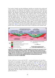
<strong>Uranium</strong> <strong>ore</strong>-<strong>forming</strong> <strong>systems</strong> <strong>of</strong> <strong>the</strong> Lake Frome regionPRESERVATION: Cenozoic age & lack <strong>of</strong> erosion; switch to dryer climate?TIMEE (Q4)NERGYTopographyRadiogenic granitesTectoniccompressionSOURCES <strong>of</strong>metals, fluids,ligands, sulfur(Q3)Fluid focussing: paleochannels; Poontana Inlier faultsPERMEABILITY (Q2, Q4):Cambrian Cenozoic & Beverley sandsbasin faults; Mesozoic Eyre FmAquifer units basin faults; Cadna-owieNamba Fm;Eyre Fm; Cadna-owie Fm<strong>Uranium</strong>: Proterozoicigneous and/or Cenozoicand/or Mesozoic basinsediments.Fluids: Meteoric water orgroundwater or formationwaters.Cenozoic sediments:Organic matterPyriteIlmeniteBacteria?Mesozoic seds:C, Fe 2+ , S 2-Cambrian seds:CH 4 , H 2 S?DEPOSITIONALGRADIENTS(Q5)Craton Regional/basin District Deposit MicroSCALEFigure 1.6: Mineral system model for basin-hosted uranium mineralisation in <strong>the</strong> Lake Fromeregion.A published deposit model for uranium mineralisation in <strong>the</strong> Beverley – Four Mile area is shownin Figure 1.7. This site-specific model is based on <strong>the</strong> conventional generic model for sandstonehostedroll-front type deposits, shown in Figure 1.8, which also shows <strong>the</strong> potential role <strong>of</strong> mobilereductants sourced from oil or gas reservoirs. Figure 1.6 differs in that it allows for multiple <strong>ore</strong><strong>forming</strong>scenarios, for example involving a range <strong>of</strong> depositional gradients or uranium sources.By identifying and mapping <strong>the</strong> mineral system components without bias towards any particularmodel we aim to generate new ‘search spaces’ for uranium exploration in <strong>the</strong> region.Figure 1.7: Schematic cross section <strong>of</strong> <strong>the</strong> Mt Painter Inlier - Lake Frome area, from Brugger et al.(2005).Page 9 <strong>of</strong> 151
<strong>Uranium</strong> <strong>ore</strong>-<strong>forming</strong> <strong>systems</strong> <strong>of</strong> <strong>the</strong> Lake Frome regionFigure 1.8: Diagrammatic section <strong>of</strong> sandstone (yellow unit) hosted uranium system, showing process<strong>of</strong> infiltration <strong>of</strong> oxidised U-bearing groundwaters and formation <strong>of</strong> roll-front and tabular styles <strong>of</strong>uranium deposits. The potential role <strong>of</strong> mobile reductants is also shown. Source: Jaireth et al.(2008a).1.4 REPORT STRUCTUREThis report is structured around <strong>the</strong> mineral system components illustrated in Figures 1.2 and 1.5.Following this Introduction, Chapter 2 addresses aspects <strong>of</strong> <strong>the</strong> uranium source by describing <strong>the</strong>lithostratigraphy <strong>of</strong> Proterozoic basement and Cambrian, Mesozoic and Cenozoic basin sediments.Chapter 3 describes <strong>the</strong> permeability architecture and evolution in terms <strong>of</strong> regional structuralevolution including neotectonics, and geometry <strong>of</strong> aquifer units in <strong>the</strong> Lake Frome region. Basedon compilations <strong>of</strong> existing public-domain data including seismic data, <strong>the</strong>se 3D datasets(viewable as 3D pdf files) highlight <strong>the</strong> geometry <strong>of</strong> basin-controlling faults <strong>of</strong> different ages.Aspects <strong>of</strong> <strong>the</strong> energy driver component <strong>of</strong> <strong>the</strong> mineral system are also discussed in this chapterbecause a key driver <strong>of</strong> fluid flow was topography, which is largely a product <strong>of</strong> tectonicprocesses and climate.Depositional gradients at district to deposit scales are described in Chapter 4. A new method <strong>of</strong>mapping and visualising geology and mineralogy in 3D is introduced, with application to mappingvariations in oxidation-reduction potential within basin sequences (chemical architecture).In Chapter 5 we describe uranium deposits <strong>of</strong> <strong>the</strong> Lake Frome region based on a review <strong>of</strong>published information. These descriptions focus on <strong>the</strong> deposit-scale geology including aspects <strong>of</strong><strong>the</strong> permeability architecture and depositional gradients at this scale.Detailed new petrographic descriptions for <strong>the</strong> Four Mile deposit are presented in Chapter 6. Thiswork addresses <strong>the</strong> depositional gradients at deposit- to micro-scale, and identifies some <strong>of</strong> <strong>the</strong>key mineralogical characteristics representing <strong>the</strong> processes <strong>of</strong> uranium <strong>ore</strong> deposition.In Chapters 2-6 a range <strong>of</strong> sources, permeable pathways, energy drivers, and depositionalgradients are described for uranium mineral <strong>systems</strong> <strong>of</strong> <strong>the</strong> Lake Frome region. It follows thatdiffering combinations <strong>of</strong> <strong>the</strong>se geological components will result in a range <strong>of</strong> hypo<strong>the</strong>ticalscenarios <strong>of</strong> uranium <strong>ore</strong> formation, each with possibly different implications for exploration. Thescenario published by Brugger et al. (2005) is just one <strong>of</strong> several that can be tested for <strong>the</strong> LakeFrome region. Chapter 7 presents <strong>the</strong> results <strong>of</strong> numerical modelling <strong>of</strong> regional- and district-Page 10 <strong>of</strong> 151
<strong>Uranium</strong> <strong>ore</strong>-<strong>forming</strong> <strong>systems</strong> <strong>of</strong> <strong>the</strong> Lake Frome regionscale fluid flow to test <strong>the</strong> scenario <strong>of</strong> Brugger et al. (2005) as well as o<strong>the</strong>r geological scenarios.A prime aim <strong>of</strong> this work is to identify <strong>the</strong> relative importance <strong>of</strong> parameters such as permeabilityfor differing regional geometric scenarios, ra<strong>the</strong>r than to attempt to model in detail <strong>the</strong> formation<strong>of</strong> particular deposits. The results help to clarify which characteristics <strong>of</strong> <strong>the</strong> basin are mostfavourable for sandstone-hosted uranium mineralisation.Finally, Chapter 8 syn<strong>the</strong>sises <strong>the</strong> key results <strong>of</strong> <strong>the</strong> study, and presents exploration criteria toassist in reducing <strong>the</strong> risk in discovery <strong>of</strong> <strong>the</strong> next large uranium deposit in <strong>the</strong> Lake Frome region.Page 11 <strong>of</strong> 151
<strong>Uranium</strong> <strong>ore</strong>-<strong>forming</strong> <strong>systems</strong> <strong>of</strong> <strong>the</strong> Lake Frome region2. <strong>Uranium</strong> sources: lithology and stratigraphyAllison Britt, Roger Skirrow, Simon van der Wielen2.1 LITHOSTRATIGRAPHY OF THE PROTEROZOIC BASEMENTCambrian to Cenozoic basins <strong>of</strong> <strong>the</strong> Lake Frome region overlie Proterozoic basement <strong>of</strong> unusuallyuranium-rich character. These basins are bounded to <strong>the</strong> south by Paleoproterozoicmetasedimentary and metaigneous rocks <strong>of</strong> <strong>the</strong> Willyama Supergroup, deposited up to ~1640 Maand metamorphosed during <strong>the</strong> Olarian Orogeny at ~1600 Ma. This sequence forms a major part<strong>of</strong> <strong>the</strong> Curnamona Province. Whereas <strong>the</strong> metasedimentary strata <strong>of</strong> <strong>the</strong> Willyama Supergroup arenot unusually endowed with uranium, several granitoid suites emplaced between ~1730 and ~1580Ma have elevated uranium contents. These include alkaline I-type granitoid rocks in <strong>the</strong> CrockersWell area that are associated with a number <strong>of</strong> small uranium deposits and occurrences. Thesegranitoids intruded metamorphic rocks <strong>of</strong> <strong>the</strong> Willyama Supergroup at ~1580 Ma (Ludwig andCooper, 1984) and have isotopic compositions suggesting involvement <strong>of</strong> possibly anomalous,metasomatised, mantle (Ru<strong>the</strong>rford et al., 2007). The Radium Hill uranium-radium deposit in <strong>the</strong>sou<strong>the</strong>rn Curnamona Province (McKay and Miezitis, 2001) also appears to be associated with synorpost-orogenic intrusive rocks.The north-south Benagerie Ridge occupies <strong>the</strong> central part <strong>of</strong> <strong>the</strong> Curnamona Province and isentirely concealed by Cambrian and younger sedimentary basins. The geology is poorlyunderstood but is known to include <strong>the</strong> early Mesoproterozoic Benagerie Volcanics, a flat lyingsequence <strong>of</strong> unmetamorphosed dominantly felsic volcanic rocks compositionally similar to <strong>the</strong>Gawler Range Volcanics in <strong>the</strong> Gawler Craton to <strong>the</strong> west. A number <strong>of</strong> small but significant ironoxide copper-gold (IOCG) deposits are known from <strong>the</strong> Benagerie Ridge and sou<strong>the</strong>rn CurnamonaProvince, including <strong>the</strong> Portia and Kalkaroo deposits. The North Portia deposit contains uraninite(Teale and Fanning, 2000), whereas deposits fur<strong>the</strong>r south appear to be less uraniferous (Williamsand Skirrow, 2000).The Mt Painter and Mt Babbage Inliers situated along <strong>the</strong> nor<strong>the</strong>astern margin <strong>of</strong> <strong>the</strong> CurnamonaProvince comprise early Mesoproterozoic metasedimentary and metaigneous rocks with acomplex tectonic history. The effects <strong>of</strong> <strong>the</strong> Cambro-Ordovician Delamerian Orogeny werelocally intense, with granite intrusion and metamorphism up to amphibolite facies.The Mt Painter and Babbage Inliers include granites with some <strong>of</strong> <strong>the</strong> highest uranium contents <strong>of</strong>any igneous rocks in <strong>Australia</strong>. For example, <strong>the</strong> early Mesoproterozoic Yerila Granite in <strong>the</strong>Babbage Inlier contains an average <strong>of</strong> 116 ppm uranium (Neumann et al., 2000). Numerousuranium prospects are present in <strong>the</strong> Mt Painter Inlier, containing uraninite, torbernite, autuniteand o<strong>the</strong>r uranium minerals (Drexel and Major, 1990; McKay and Miezitis, 2001). At <strong>the</strong> Mt Geeprospect breccia-hosted uranium mineralisation with anomalous REE contents and raremolybdenite occurs in <strong>the</strong> hematite-chlorite-rich matrix between granitic clasts. The breccias areunmetamorphosed, and may have formed in <strong>the</strong> Late Ordovician to Silurian (Drexel and Major,1990; McKay and Miezitis, 2001; Elburg et al., 2003), or Permo-Carboniferous (Idnurm andHeinrich, 1993).The Mt Painter and Babbage Inliers and sou<strong>the</strong>rn Curnamona Province represent highlyuraniferous crust, in <strong>the</strong> form <strong>of</strong> both magmatic and hydro<strong>the</strong>rmal enrichments. These arepotentially excellent sources <strong>of</strong> uranium for basin-related uranium mineral <strong>systems</strong>, whe<strong>the</strong>rdirectly via leaching or indirectly via erosion <strong>of</strong> uranium-rich detritus into flanking basins.However, <strong>the</strong> relative importance <strong>of</strong> <strong>the</strong> various potential sources depends partly upon <strong>the</strong>mineralogy <strong>of</strong> <strong>the</strong> uranium-bearing phases and <strong>the</strong> chemical stability <strong>of</strong> <strong>the</strong>se minerals (seeSkirrow et al., 2009, and references <strong>the</strong>rein). Minerals that are relatively soluble in oxidisedfluids, such as uraninite, <strong>of</strong>fer a good source, whereas refractory uranium-bearing phases such asbrannerite (e.g., Crocker Well), davidite (e.g., Mt Victoria) or zircon are unlikely to represent aviable source unless <strong>the</strong> minerals are metamict (Cuney and Kyser, 2008) or partially wea<strong>the</strong>red.Page 12 <strong>of</strong> 151
<strong>Uranium</strong> <strong>ore</strong>-<strong>forming</strong> <strong>systems</strong> <strong>of</strong> <strong>the</strong> Lake Frome regionThe abundance <strong>of</strong> magmatic-hydro<strong>the</strong>rmal and related ‘primary’ uranium mineralisation in <strong>the</strong> MtPainter Inlier and sou<strong>the</strong>rn Curnamona Province may be one key factor in determining <strong>the</strong> fertility<strong>of</strong> <strong>the</strong> Frome region for ‘secondary’ basin-related uranium <strong>systems</strong>.2.2 LITHOSTRATIGRAPHY OF PHANEROZOIC BASINSParts <strong>of</strong> <strong>the</strong> Cambrian Arrowie Basin (Fig. 2.1) are preserved beneath younger basins in <strong>the</strong> LakeFrome region and crop out in <strong>the</strong> nor<strong>the</strong>rn Flinders Ranges. The Paleozoic strata areunconformably overlain by Mesozoic units <strong>of</strong> <strong>the</strong> very extensive Eromanga Basin, which locallyonlaps onto Proterozoic basement. The lobe <strong>of</strong> <strong>the</strong> Eromanga Basin extending southwards into <strong>the</strong>Lake Frome region is known as <strong>the</strong> Frome Embayment.The Mesozoic units are overlain by Cenozoic sediments <strong>of</strong> <strong>the</strong> Lake Eyre Basin. The CallabonnaSub-basin constitutes that part <strong>of</strong> <strong>the</strong> Lake Eyre Basin bounded to <strong>the</strong> west by <strong>the</strong> Flinders Rangesand Mt Painter Inlier, to <strong>the</strong> south by <strong>the</strong> outcropping Curnamona Province, and to <strong>the</strong> east by <strong>the</strong>Barrier Ranges.Figure 2.1: Distribution <strong>of</strong> Cambrian rocks <strong>of</strong> <strong>the</strong> Arrowie Basin in relation to Proterozoic domains inSouth <strong>Australia</strong> and western New South Wales. The Olary and Broken Hill Domains form <strong>the</strong> sou<strong>the</strong>rnpart <strong>of</strong> <strong>the</strong> Curnamona Province. The outline <strong>of</strong> Lake Frome is shown within <strong>the</strong> area <strong>of</strong> <strong>the</strong> Moorowie‘Syncline’ or sub-basin. Source: Gravestock and Cowley (1995).Page 13 <strong>of</strong> 151
<strong>Uranium</strong> <strong>ore</strong>-<strong>forming</strong> <strong>systems</strong> <strong>of</strong> <strong>the</strong> Lake Frome region2.2.1 Paleozoic – Arrowie BasinIn <strong>the</strong> study area <strong>the</strong> Arrowie Basin is represented by <strong>the</strong> Moorowie and Yalkalpo ‘Synclines’ orsub-basins which contain thick unfolded strata to <strong>the</strong> west and east, respectively, <strong>of</strong> <strong>the</strong> BenagerieRidge (Gravestock and Cowley, 1995, Figs. 2.1, 2.2). The Arrowie Basin is comprised <strong>of</strong>shallow marine sedimentary siliciclastic and carbonate deposits. The succession has beensubdivided into three sequences: Є1, a carbonate dominated sequence that progrades intoevaporite facies at <strong>the</strong> top <strong>the</strong> sequence; Є2, a redbed and carbonate sequence, and Є3, a thickpackage <strong>of</strong> red sandstones that coarsen up-sequence (Drexel, et al., 1993). Between sequences Є1and Є2 minor episodic tectonic and volcanic activity occurred.Petroleum exploration in <strong>the</strong> Moorowie sub-basin delineated a number <strong>of</strong> ‘shows’ but nosignificant discoveries have been made.Figure 2.2: Stratigraphic relationship diagram for <strong>the</strong> Arrowie Basin showing <strong>the</strong> correlation betweenlithologies and sequences. Source: Gravestock and Cowley (1995).2.2.2 Mesozoic – Eromanga BasinThe Eromanga Basin is an intracratonic sag basin covering some million square kilometres <strong>of</strong>east-central <strong>Australia</strong> (Fig. 2.3). A detailed stratigraphic framework for <strong>the</strong> Eromanga andadjacent basins was constructed by Gravestock et al. (1986), Krieg (1995) and Radke et al. (2000),among o<strong>the</strong>rs. The Eromanga Basin has been subdivided into three main stratigraphic sequences:a lower non-marine sequence (early Jurassic to earliest Cretaceous), a middle marine sequence(early Cretaceous) and an upper non-marine sequence (late Cretaceous).The lower non-marine sequence consists <strong>of</strong> medium-grained sands deposited in a braided fluvialenvironment, followed by fine-grained lacustrine sands, silts and shales. Volcaniclastic material ism<strong>ore</strong> abundant in <strong>the</strong> lower non-marine succession to <strong>the</strong> north and east <strong>of</strong> <strong>the</strong> Frome Embayment,Page 14 <strong>of</strong> 151
<strong>Uranium</strong> <strong>ore</strong>-<strong>forming</strong> <strong>systems</strong> <strong>of</strong> <strong>the</strong> Lake Frome regionpossibly sourced from volcanism in <strong>the</strong> east (Krieg, et al. 1995). The middle marine sequencecomprises basal sands, <strong>of</strong> which <strong>the</strong> Cadna-owie Formation occurs in <strong>the</strong> Frome Embayment,prograding into deeper water shales and muds. Felsic volcanic detritus from <strong>the</strong> U-rich GawlerRange Volcanics also occurs in <strong>the</strong> Mt Anna Sandstone, equivalent to <strong>the</strong> Cadna-owie Formation,along <strong>the</strong> southwestern margin <strong>of</strong> <strong>the</strong> basin (west <strong>of</strong> Lake Torrens). Of <strong>the</strong> shales and muds, <strong>the</strong>Cretaceous Bulldog Shale is <strong>the</strong> uppermost <strong>of</strong> <strong>the</strong> Eromanga Basin units present in <strong>the</strong> study area.It is described by Ellis (1976) as monotonous blue-grey silty clay. The upper non-marinesequence, <strong>the</strong> Winton Formation, does not occur in <strong>the</strong> Frome Embayment. It comprises athousand-metre thick package <strong>of</strong> sediments (sandstones, shales and siltstones) that was depositedin a low-energy fluvial to lacustrine environment. Detrital feldspars and ferromagnesian mineralsare thought to have been sourced from active volcanoes in eastern <strong>Australia</strong> (Krieg et al., 1995).The Great Artesian Basin (GAB) is synonymous with <strong>the</strong> Eromanga Basin, although <strong>the</strong> aquiferunits are not coincident with <strong>the</strong> sedimentary limits. The main artesian aquifer comprises anumber <strong>of</strong> formations below and including <strong>the</strong> Cadna-owie Formation, whereas <strong>the</strong> upperconfined aquifer occurs within <strong>the</strong> upper non-marine sequence (Krieg et al., 1995). Artesianwaters from <strong>the</strong> GAB debouch onto <strong>the</strong> surface at a number <strong>of</strong> mound springs in <strong>the</strong> Lake Fromeregion.Organic matter is abundant in several units <strong>of</strong> <strong>the</strong> Eromanga Basin, including <strong>the</strong> Bulldog Shale in<strong>the</strong> Frome Embayment. Coal seams are present in <strong>the</strong> lower and upper non-marine successions(e.g., Birkhead Formation, Winton Formation). In <strong>the</strong> Moomba region to <strong>the</strong> north, oil and gashave been recovered from almost all <strong>of</strong> <strong>the</strong> lower non-marine units. While much <strong>of</strong> <strong>the</strong>sehydrocarbons are believed to have migrated upwards from <strong>the</strong> Cooper Basin, some units in <strong>the</strong>lower marine Eromanga Basin contain abundant organic matter and are oil mature (Krieg et al.,1995). It is unclear whe<strong>the</strong>r Mesozoic rocks in <strong>the</strong> Frome Embayment experienced <strong>the</strong> migration<strong>of</strong> hydrocarbons derived ei<strong>the</strong>r from within <strong>the</strong> Eromanga Basin or from <strong>the</strong> underlying Cambrianstrata.Page 15 <strong>of</strong> 151
<strong>Uranium</strong> <strong>ore</strong>-<strong>forming</strong> <strong>systems</strong> <strong>of</strong> <strong>the</strong> Lake Frome regionFigure 2.3: Extents <strong>of</strong> Cooper and Eromanga Basins in South <strong>Australia</strong>. Source:Krieg (1995).2.2.3 Cenozoic – Lake Eyre BasinThe Lake Eyre Basin was created by tectonic subsidence commencing in <strong>the</strong> late Paleocene wi<strong>the</strong>pisodic fluvial and lacustrine sedimentation occurring in <strong>the</strong> basin until <strong>the</strong> present day (Callen etal., 1995). The Eyre Formation is <strong>the</strong> basal unit <strong>of</strong> <strong>the</strong> Lake Eyre Basin and unconformablyoverlies <strong>the</strong> Eromanga Basin. Sedimentation spanned <strong>the</strong> latest Paleocene to <strong>the</strong> Middle Eocene.The Eyre Formation comprises pyritic, carbonaceous mature sand <strong>of</strong> varying grain size rangingPage 16 <strong>of</strong> 151
<strong>Uranium</strong> <strong>ore</strong>-<strong>forming</strong> <strong>systems</strong> <strong>of</strong> <strong>the</strong> Lake Frome regionfrom silt to gravel with small cobbles in places, and was deposited by braided streams (Alley andBenbow, 1995). In <strong>the</strong> Callabonna Sub-basin, <strong>the</strong> Eyre Formation incorporates <strong>the</strong> MurnpeowieFormation, which contains clay, lignite and basal gravels.A network <strong>of</strong> paleochannels filled by Eyre Formation sediments is recognised in <strong>the</strong> Lake Fromeregion, incising <strong>the</strong> underlying Cretaceous units <strong>of</strong> <strong>the</strong> Eromanga Basin or directly intoProterozoic basement in places. These paleochannels are important as hosts to many <strong>of</strong> <strong>the</strong>uranium deposits in <strong>the</strong> region, including <strong>the</strong> Honeymoon, Oban and Goulds Dam deposits (Curtiset al., 1990). In <strong>the</strong> sou<strong>the</strong>rn part <strong>of</strong> <strong>the</strong> Callabonna Sub-basin <strong>the</strong> paleochannels have a generalnor<strong>the</strong>rly trend and indicate sediment transport from south to north. Although <strong>the</strong> Eyre Formationhosts <strong>the</strong> Four Mile deposit (Alliance Resources, 2009, www.allianceresources.com.au) it is notclear whe<strong>the</strong>r a paleochannel is present in this area.There is little evidence for fur<strong>the</strong>r sedimentation in <strong>the</strong> Lake Eyre Basin until <strong>the</strong> late Oligocenewhen widespread gentle folding and uplift rejuvenated <strong>the</strong> Birdsville Track Ridge some 200 km to<strong>the</strong> north <strong>of</strong> <strong>the</strong> Callabonna Sub-basin. This activity split <strong>the</strong> Lake Eyre Basin into <strong>the</strong> Tirari andCallabonna Sub-basins and revived sedimentation which continued to <strong>the</strong> Pliocene. The newsediments comprise <strong>the</strong> Namba Formation which disconformably overlies <strong>the</strong> Eyre Formation.The Namba Formation is equivalent to <strong>the</strong> Etadunna Formation and this name is commonly usedin <strong>the</strong> historical drill hole logs from <strong>the</strong> Lake Frome region, though <strong>the</strong> Etadunna Formation isnow restricted to <strong>the</strong> Tirari Sub-basin.The Namba Formation sediments are described by Alley and Benbow (1995) as grey, green andwhite clays, fine-grained sand and carbonate, and minor conglomerate. The formation wasdeposited in a fluvial lacustrine environment with meandering streams and billabongs. Relief in<strong>the</strong> region is believed to have been low during deposition <strong>of</strong> <strong>the</strong> Namba Formation. The NambaFormation averages 90m thickness, thinning over <strong>the</strong> Benagerie Ridge and thickening up to 170mtowards <strong>the</strong> Barrier and Flinders Ranges. However, in detail some areas show <strong>the</strong> oppositethickening trends, for example in <strong>the</strong> EL5/6 area to <strong>the</strong> east <strong>of</strong> Lake Frome (see Chapter 4 and Fig.4.3). Drill hole logs from <strong>the</strong> Lake Frome region typically record unconsolidated, very fine- t<strong>of</strong>ine-grained angular sands, black carbonaceous clay, green and grey clays, dolomitic mud and, inplaces, lignite. At <strong>the</strong> Beverley deposit <strong>the</strong> Namba Formation comprises three members: a lowerinterval known as <strong>the</strong> Alpha Mudstone which contains plant fragments and carbonised wood; <strong>the</strong>overlying Beverley Sands (grey silt with sandstone lenses) that host uranium mineralisation, and<strong>the</strong> overlying Beverley Clay (Curtis et al., 1990). Sinuous sand-filled depressions in <strong>the</strong> uppersurface <strong>of</strong> <strong>the</strong> Alpha Mudstone host much <strong>of</strong> <strong>the</strong> uranium mineralisation, and are interpreted t<strong>ore</strong>present parts <strong>of</strong> a broadly north-trending paleochannel system (McConachy et al., 2006).2.2.4 QuaternaryQuaternary processes have created <strong>the</strong> present-day fans, claypans, playas, dunes and ephemeralstreams <strong>of</strong> <strong>the</strong> Callabonna Sub-basin. The oldest Quaternary unit, <strong>the</strong> Willawortina Formation,formed as piedmont fans around <strong>the</strong> Flinders and Olary Ranges, with sedimentation commencingin <strong>the</strong> late Cenozoic and continuing until <strong>the</strong> Plio-Pleistocene. The Willawortina Formationcomprises fine and coarse facies (Callen et al., 1995). The fine facies is an upwards fining,cyclical sequence <strong>of</strong> sandy mud and silty dolomite, with distal fan, mudflow and playa-lacustrinecomplexes represented by outcrops <strong>of</strong> green clay and thick, calcareous paleosols (Callen et al.,1995). The coarse facies, represented in drill holes around <strong>the</strong> Beverley uranium deposit,comprises braided fans <strong>of</strong> coarse, framework-supported gravels as well as poorly sorted, matrixsupporteddebris flows (Callen et al., 1995).The Coomb Spring and Millyera Formations were deposited from <strong>the</strong> mid to late Pleistocene(Callen and Benbow, 1995). The beach deposits <strong>of</strong> <strong>the</strong> Coomb Spring Formation occur aroundLake Frome and consist <strong>of</strong> white to yellow, <strong>of</strong>ten coarse-grained, well-sorted sand (Callen andBenbow, 1995). Present-day topographic contours suggest that it was deposited when lake levelswere higher and Lakes Frome and Eyre were possibly joined (Callen and Benbow, 1995). ThesePage 17 <strong>of</strong> 151
<strong>Uranium</strong> <strong>ore</strong>-<strong>forming</strong> <strong>systems</strong> <strong>of</strong> <strong>the</strong> Lake Frome regionCoomb Spring Formation intertongues with <strong>the</strong> flood-plain and lacustrine deposits <strong>of</strong> <strong>the</strong> MillyeraFormation, which consists <strong>of</strong> greenish clay, thin algal limestone and fine-grained white to greenishsand (Callen and Benbow, 1995).Late Pleistocene sedimentation also resulted in <strong>the</strong> deposition <strong>of</strong> <strong>the</strong> Eurinilla Formation, found in<strong>the</strong> nor<strong>the</strong>rn Callabonna Sub-basin and near Lake Frome. It also intertongues with <strong>the</strong> MillyeraFormation and was party deposited in paleochannels formed within <strong>the</strong> Willawortina Formation(Callen and Benbow, 1995). The Eurinilla Formation consists <strong>of</strong> bright red-brown to yellowbrownsand and gravel <strong>of</strong> intermittent streams and <strong>the</strong>ir overbank deposits (Callen and Benbow,1995).The youngest unit in <strong>the</strong> Callabonna Sub-basin is <strong>the</strong> late Pleistocene to Holocene CoonarbineFormation, consisting <strong>of</strong> aeolian sands <strong>of</strong> red-coated, frosted quartz grains, yellow to orangegrains, clay pellets and gypsum flakes with aeolian cross-bedding (Callen and Benbow, 1995).The sands form a striking pattern <strong>of</strong> longitudinal dunes, with wind-eroded claypans alignedobliquely. The dunes are typically up to 15m high (Callen and Benbow, 1995) and trendnorthwards in <strong>the</strong> nor<strong>the</strong>rn part <strong>of</strong> <strong>the</strong> study area. With Lake Frome as an axis, <strong>the</strong>ir orientationprogressively rotates to an east-north-easterly trend in <strong>the</strong> sou<strong>the</strong>rn part <strong>of</strong> <strong>the</strong> sub-basin (Randell,1973; Callen and Benbow, 1995). Older dunes contain calcareous paleosols and a greaterproportion <strong>of</strong> clay compared to <strong>the</strong> younger phases <strong>of</strong> dune formation (Callen and Benbow, 1995).Large transverse dunes also formed along <strong>the</strong> downwind margins <strong>of</strong> playas and claypans and on<strong>the</strong> bed <strong>of</strong> Lake Frome. Gypsum dunes are built upon clay dunes indicating deflation <strong>of</strong> <strong>the</strong> lakefloor clays followed by exposure and deflation <strong>of</strong> <strong>the</strong> groundwater gypsum horizon (Callen andBenbow, 1995).Table 2.1: Quaternary units in <strong>the</strong> Callabonna Sub-basin. After Callen and Benbow (1995).Formation Age Maximum Thickness (m) Depositional EnvironmentCoonarbine Formation Pleistocene-Holocene 50 DunefieldEurinilla Formation Late Pleistocene 10 AlluvialCoomb Spring Formation Mid-Late Pleistocene 8 Lacustrine Sh<strong>ore</strong>lineMillyera Formation Mid-Late Pleistocene 9 Playa-lacustrineWillawortina Formation Plio-Pleistocene 100 Alluvial and lacustrinePage 18 <strong>of</strong> 151
<strong>Uranium</strong> <strong>ore</strong>-<strong>forming</strong> <strong>systems</strong> <strong>of</strong> <strong>the</strong> Lake Frome region3. 3D architecture and permeabilitySimon van der Wielen, Allison Britt, Roger Skirrow3.1 INTRODUCTIONFaults and permeable sedimentary units comprise <strong>the</strong> fundamental permeability architecture foruranium and o<strong>the</strong>r basin-related mineral <strong>systems</strong> in <strong>the</strong> region. This architecture is important infocussing fluids at scales ranging from crustal to basin to deposit. The structural and basinarchitecture is a product ultimately <strong>of</strong> <strong>the</strong> geodynamic and tectono<strong>the</strong>rmal evolution, aspects <strong>of</strong>which are described in <strong>the</strong> first section below. The 3D structural architecture is <strong>the</strong>n documented,based on previous work and on newly compiled 3D datasets such as seismic transects. A series <strong>of</strong>figures <strong>of</strong> <strong>the</strong> architecture are presented as 3D pdf files. Finally, <strong>the</strong> 3D geometry <strong>of</strong> Cenozoicunits including <strong>the</strong> Eyre and Namba formations is presented for a case study area to <strong>the</strong> nor<strong>the</strong>ast<strong>of</strong> Lake Frome. These units represent some <strong>of</strong> <strong>the</strong> key permeability components in uraniummineral <strong>systems</strong> in <strong>the</strong> region.The chemical architecture and mapping methodology is presented in Chapter 4.3.2 TECTONIC AND THERMAL EVOLUTION<strong>Uranium</strong> mineral <strong>systems</strong> <strong>of</strong> <strong>the</strong> Lake Frome region occur within a part <strong>of</strong> <strong>the</strong> <strong>Australia</strong>ncontinental crust that appears to be unusually enriched in heat-producing elements includinguranium. The South <strong>Australia</strong>n Heat Flow Anomaly extends over a broad region between <strong>the</strong> MtPainter Inlier in <strong>the</strong> east and <strong>the</strong> eastern Gawler Craton in <strong>the</strong> west, and includes <strong>the</strong> FlindersRanges (Neumann et al., 2000). A significant proportion <strong>of</strong> <strong>the</strong> heat production is sourced fromupper crustal felsic igneous rocks with elevated uranium, thorium and potassium contents(Neumann et al., 2000). McLaren et al. (2002) contended that a major <strong>the</strong>rmal contribution during<strong>the</strong> Delamerian Orogeny in <strong>the</strong> Mt Painter region originated from this anomalous high-heatproducingcrust and that intense deformation was guided by zones <strong>of</strong> <strong>the</strong>rmally weakened crust.The region <strong>the</strong>n experienced <strong>the</strong> effects <strong>of</strong> <strong>the</strong> Alice Springs Orogeny in <strong>the</strong> period ~310-260 Ma,accompanied by exhumation and cooling (Mitchell et al., 2002). Similarly, Célérier et al. (2005)proposed that <strong>the</strong> present-day topography <strong>of</strong> <strong>the</strong> Flinders Ranges including <strong>the</strong> Mt Painter Inliercan be explained by Paleogene to Cenozoic inversion and faulting focussed on zones <strong>of</strong> <strong>the</strong>rmallyweakened crust. Apatite fission track dating indicates significant exhumation (1.5-2.0 km) andcooling commencing as early as <strong>the</strong> Paleocene (~65 Ma) or late Cretaceous (Mitchell et al., 2002).However, heating above ~100°C appears to have persisted along <strong>the</strong> Paralana Fault until ~20-25Ma, possibly as a result <strong>of</strong> hydro<strong>the</strong>rmal fluid circulation that largely switched <strong>of</strong>f after this time(Foster et al., 1994; Mitchell et al., 2002). O<strong>the</strong>r studies suggest that much <strong>of</strong> <strong>the</strong> present day reliefin <strong>the</strong> Mt Painter Inlier could have been generated since ~4 Ma (Quigley et al., 2007). Increasingstrain during <strong>the</strong> Neogene may be a result <strong>of</strong> plate boundary forcing as <strong>Australia</strong>n platecommenced its rapid northwards drift (Célérier et al., 2005; Sandiford et al., 2005).The <strong>the</strong>me <strong>of</strong> repeated uplift and deformation occurring in parts <strong>of</strong> <strong>the</strong> South <strong>Australia</strong> Heat FlowAnomaly is potentially important in <strong>the</strong> development <strong>of</strong> basin-related uranium mineral <strong>systems</strong>.First, uplifted uranium-rich basement may have provided both a plentiful source <strong>of</strong> uranium forleaching by surficial waters as well as <strong>the</strong> topographic driver for fluid flow into adjacent basins.Second, erosion may have provided uranium-rich detritus to basins flanking <strong>the</strong> uplands, whichare potentially a secondary source <strong>of</strong> uranium. Third, one <strong>of</strong> <strong>the</strong> modes <strong>of</strong> intraplate compressivedeformation proposed for <strong>the</strong> Flinders Ranges (long-wavelength elastic deformation) resulted intopographic lows bordering <strong>the</strong> ranges to <strong>the</strong> east and west, now occupied by Lake Frome andLake Torrens (Célérier et al., 2005). During wetter climatic periods such lake <strong>systems</strong> may haveaccumulated abundant organic matter, which is potentially effective as a reductant to precipitateuranium from oxidised waters (see also Chapter 4).Page 19 <strong>of</strong> 151
<strong>Uranium</strong> <strong>ore</strong>-<strong>forming</strong> <strong>systems</strong> <strong>of</strong> <strong>the</strong> Lake Frome regionNamba FormationFigure 3.1: Summary <strong>of</strong> Late Mesozoic and Cenozoic events in <strong>the</strong> Lake Frome region, includinglithostratigraphy, tectonic evolution, deep wea<strong>the</strong>ring episodes, and possible timing <strong>of</strong> hypo<strong>the</strong>ticaluranium mineral <strong>systems</strong>. See text for sources <strong>of</strong> data and discussion.The timing <strong>of</strong> deformation and uplift is critical for generation <strong>of</strong> a productive uranium mineralsystem. Uplift in <strong>the</strong> late Cretaceous and Paleocene potentially may have been effective in drivingfluid flow in <strong>the</strong> Mesozoic aquifers <strong>of</strong> <strong>the</strong> Eromanga Basin. Increasing intraplate stress andtopography generation in <strong>the</strong> Eocene conceivably would have provided <strong>the</strong> potential energy forfluid flow through <strong>the</strong> Eyre Formation which was being deposited during this period, and througholder aquifers. The commencement <strong>of</strong> <strong>the</strong> latest major period <strong>of</strong> uplift around 6-10 Ma possiblyPage 20 <strong>of</strong> 151
<strong>Uranium</strong> <strong>ore</strong>-<strong>forming</strong> <strong>systems</strong> <strong>of</strong> <strong>the</strong> Lake Frome regiondrove fluids through <strong>the</strong> permeable units <strong>of</strong> <strong>the</strong> previously deposited Namba Formation. Finally,<strong>the</strong> current topographic head is <strong>the</strong> potential energy source for fluid flow through <strong>the</strong> WillawortinaFormation and potentially also into underlying aquifers such as <strong>the</strong> Namba and Eyre Formations.Thus <strong>the</strong> interplay <strong>of</strong> climatic and tectonic evolution may influence <strong>the</strong> region’s potential for largeuranium mineral <strong>systems</strong>. These mineral system scenarios are expl<strong>ore</strong>d in m<strong>ore</strong> detail in Chapter5 (section 5.4), Chapter 7 and Chapter 8.3.3 STRUCTURAL ARCHITECTURE AND BASIN FILL GEOMETRY3.3.1 Data compilation for 3D geological map constructionThe Lake Frome region has been a focus for uranium exploration since <strong>the</strong> late 1960s (Curtis etal., 1990), and extensive historical exploration data exists in various analogue and digital forms.Through <strong>the</strong> compilation and modelling <strong>of</strong> seismic, lithological, hydrological and drill log datawith modern computing s<strong>of</strong>tware it is possible to provide new insights into <strong>the</strong> three-dimensionalstructure and chemical architecture <strong>of</strong> this important uranium province.To better understand <strong>the</strong> fault and lithological architecture within <strong>the</strong> study area a 3D model wasconstructed using gOcad s<strong>of</strong>tware. The following datasets were integrated into <strong>the</strong> Frome 3Dmap:The 9 second AusDEM v2 (<strong>Geoscience</strong> <strong>Australia</strong>, 2002) with 270 m and 90 m pixelresolution, respectively. As both DEMs are national datasets <strong>the</strong>y were converted fromgeographic coordinates (latitude and longitude, Geocentric Datum <strong>of</strong> <strong>Australia</strong> 1994) toeastings and northings (MGA94, zone 54). The DEMs were clipped to cover <strong>the</strong> projectarea. Due to limitations in computer resources, only <strong>the</strong> 9 second AusDEM was convertedinto a gOcad 3D surface. A portion <strong>of</strong> <strong>the</strong> new 1:1,000,000 scale surface geology <strong>of</strong> <strong>Australia</strong> (Raymond, 2009)was extracted for <strong>the</strong> study area and imported into gOcad as curves (Fig. 3.2).Seismic data were obtained from PIRSA as ‘segy’ format and imported into gOcad(Appendix 2 and Fig. 3.2).Drill hole data for <strong>the</strong> study area were compiled from public domain databases held by<strong>the</strong> South <strong>Australia</strong>, New South Wales and Queensland geological survey agencies (Fig.3.2).Cultural and physiographic datasets, such as roads (GEOMET 2391), railways (GEOMET2390), population centres (Gazetteer database, <strong>Geoscience</strong> <strong>Australia</strong>, 2005), landuse(GEOMET 3415), drainage (Lawford, et al., 2007), state boundaries (GEOMET 2383)and physiography (GEOMET 2383) were compiled.Deposit and mineral occurrence information came from two <strong>Geoscience</strong> <strong>Australia</strong>databases: OZMIN mineral deposits database (Ewers et al., 2002) and <strong>the</strong> MINLOCdatabase.Page 21 <strong>of</strong> 151
<strong>Uranium</strong> <strong>ore</strong>-<strong>forming</strong> <strong>systems</strong> <strong>of</strong> <strong>the</strong> Lake Frome regionFigure 3.2: Map showing <strong>the</strong> surface geology (Raymond, 2009), location <strong>of</strong> uranium occurrences,mineral deposits (OZMIN database), drilling and seismic lines within <strong>the</strong> 3D map boundary. The smallvaricoloured circles are <strong>the</strong> drill holes for which redox information has been determined (see Chapter4). Surface geology colours as follows: red, pink and brown tones represent Proterozoic units, bluetones are Paleozoic units, green and tan tones are Mesozoic units, and pale yellow tones representCenozoic units.Components <strong>of</strong> <strong>the</strong> 3D model have been embedded into <strong>the</strong> electronic version <strong>of</strong> this document asa series <strong>of</strong> 3D pdf images (Fig. 3.3 – Arrowie Basin seismic; Fig. 3.4 – Sou<strong>the</strong>rn margin <strong>of</strong> <strong>the</strong>Cooper Basin; Fig. 3.5 – Curnamona Province seismic; Fig. 3.6 – Eromanga Basin seismic andFig. 3.7 – Drillholes, surface geology, DEM, mineral deposits, radiometrics).Workflow and metadata for <strong>the</strong> 3D map are available on request from <strong>the</strong> authors.Page 22 <strong>of</strong> 151
<strong>Uranium</strong> <strong>ore</strong>-<strong>forming</strong> <strong>systems</strong> <strong>of</strong> <strong>the</strong> Lake Frome regionFigure 3.3 (see over): 3D PDF <strong>of</strong> seismic lines over <strong>the</strong> Arrowie Basin. In <strong>the</strong> electronic version <strong>of</strong>this document, click on <strong>the</strong> model to activate interactive viewing. Hold down <strong>the</strong> left mouse button andmove <strong>the</strong> mouse to rotate. Hold down <strong>the</strong> right mouse button and move <strong>the</strong> mouse to zoom in and out.Hold down both left and right mouse buttons and move <strong>the</strong> mouse to pan. Individual objects can beturned on and <strong>of</strong>f by using <strong>the</strong> model tree (<strong>the</strong> model tree objects are summarised in Table 3.1).Lighting and surface rendering can be modified using icon buttons that appear at <strong>the</strong> top <strong>the</strong> model.Table 31: Model tree objects for Figure 3.3.Model ObjectSeismic_Arrowie/Frome_Seismic_A_66-MPSeismic_Arrowie/Frome_Seismic_A_70-CFASeismic_Arrowie/Frome_Seismic_A_70-CFBSeismic_Arrowie/Frome_Seismic_A_70-CFCSeismic_Arrowie/Frome_Seismic_A_70-CFDSeismic_Arrowie/Frome_Seismic_A_70-CFESeismic_Arrowie/Frome_Seismic_A_70-CFFSeismic_Arrowie/Frome_Seismic_A_70-CFHSeismic_Arrowie/Frome_Seismic_A_70-CFJSeismic_Arrowie/Frome_Seismic_A_70-CFL1Seismic_Arrowie/Frome_Seismic_A_70-CFL2Seismic_Arrowie/Frome_Seismic_A_70-CFMSeismic_Arrowie/Frome_Seismic_A_70-CFNSeismic_Arrowie/Frome_Seismic_A_70-CFOSeismic_Arrowie/Frome_Seismic_A_70-CFPSeismic_Arrowie/Frome_Seismic_A_70-CFQSeismic_Arrowie/Frome_Seismic_A_70-CFRSeismic_Arrowie/Frome_Seismic_A_70-CFSSeismic_Arrowie/Frome_Seismic_A_70-CFTSeismic_Arrowie/Frome_Seismic_A_75-JCQSeismic_Arrowie/Frome_Seismic_A_70-CFKSeismic_Arrowie/Frome_Seismic_A_75-JCRSeismic_Arrowie/Frome_Seismic_A_81-CFFSeismic_Arrowie/Frome_Seismic_A_81-QLCSeismic_Arrowie/Frome_Seismic_A_81-QLDSeismic_Arrowie/Frome_Seismic_A_81-QLESeismic_Arrowie/Frome_Seismic_A_81-QLFSeismic_Arrowie/Frome_Seismic_A_81-QLGSeismic_Arrowie/Frome_Seismic_A_81-QLHSeismic_Arrowie/Frome_Seismic_A_82-QNPSeismic_Arrowie/Frome_Seismic_A_82-QNQSeismic_Arrowie/Frome_Seismic_A_82-QNRSeismic_Arrowie/Frome_Seismic_A_82-QNSSeismic_Arrowie/Frome_Seismic_A_82-QNTSeismic_Arrowie/Frome_Seismic_A_82-QNWSeismic_Arrowie/Frome_Seismic_A_82-QNXSeismic_Arrowie/Frome_Seismic_A_82-QNYSeismic_Arrowie/Frome_Seismic_A_82-QNZDescriptionSeismic line 66-MPSeismic line 70-CFASeismic line 70-CFBSeismic line 70-CFCSeismic line 70-CFDSeismic line 70-CFESeismic line 70-CFFSeismic line 70-CFHSeismic line 70-CFJSeismic line 0-CFL1Seismic line 0-CFL2Seismic line 70-CFMSeismic line 70-CFNSeismic line 70-CFOSeismic line 70-CFPSeismic line 70-CFQSeismic line 70-CFRSeismic line 70-CFSSeismic line 70-CFTSeismic line 75-JCQSeismic line 70-CFKSeismic line 75-JCRSeismic line 81-CFFSeismic line 81-QLCSeismic line 81-QLDSeismic line 81-QLESeismic line 81-QLFSeismic line 81-QLGSeismic line 81-QLHSeismic line 82-QNPSeismic line 82-QNQSeismic line 82-QNRSeismic line 82-QNSSeismic line 82-QNTSeismic line 82-QNWSeismic line 82-QNXSeismic line 82-QNYSeismic line 82-QNZPage 23 <strong>of</strong> 151
<strong>Uranium</strong> <strong>ore</strong>-<strong>forming</strong> <strong>systems</strong> <strong>of</strong> <strong>the</strong> Lake Frome regionModel ObjectSeismic_Arrowie/Frome_Seismic_A_82-QRNSeismic_Arrowie/Frome_Seismic_A_82-QRPSeismic_Arrowie/Frome_Seismic_A_82-QRQSeismic_Arrowie/Frome_Seismic_A_82-QRRSeismic_Arrowie/Frome_Seismic_A_84-SPGSeismic_Arrowie/Frome_Seismic_A_84-SPHSeismic_Arrowie/Frome_Seismic_A_84-SPJSeismic_Arrowie/Frome_Seismic_A_84-SPKSeismic_Arrowie/Frome_Seismic_A_84-SPLSeismic_Arrowie/Frome_Seismic_A_84-SPMSeismic_Arrowie/Frome_Seismic_A_84-SPNSeismic_Arrowie/Frome_Seismic_A_84-SPPSeismic_Arrowie/Frome_Seismic_A_84-SPQSeismic_Arrowie/Frome_Seismic_A_84-SPRSeismic_Arrowie/Frome_Seismic_A_84-SPSSeismic_Arrowie/Frome_Seismic_A_84-SPTSeismic_Arrowie/Frome_Seismic_A_84-SPWSeismic_Arrowie/Frome_Seismic_A_84-SPXSeismic_Arrowie/Frome_Seismic_A_84-SPYSeismic_Arrowie/Frome_Seismic_A_84-TJGSeismic_Arrowie/Frome_Seismic_A_84-TJKSeismic_Arrowie/Frome_Seismic_A_84-TNXFrome_BoundaryTopographyDescriptionSeismic line 82-QRNSeismic line 82-QRPSeismic line 82-QRQSeismic line 82-QRRSeismic line 84-SPGSeismic line 84-SPHSeismic line 84-SPJSeismic line 84-SPKSeismic line 84-SPLSeismic line 84-SPMSeismic line 84-SPNSeismic line 84-SPPSeismic line 84-SPQSeismic line 84-SPRSeismic line 84-SPSSeismic line 84-SPTSeismic line 84-SPWSeismic line 84-SPXSeismic line 84-SPYSeismic line 84-TJGSeismic line 84-TJKSeismic line 84-TNXBoundary SurfaceTopography Image draped onto <strong>the</strong> DEM SurfacePage 24 <strong>of</strong> 151
<strong>Uranium</strong> <strong>ore</strong>-<strong>forming</strong> <strong>systems</strong> <strong>of</strong> <strong>the</strong> Lake Frome regionFigure 3.3Page 25 <strong>of</strong> 151
<strong>Uranium</strong> <strong>ore</strong>-<strong>forming</strong> <strong>systems</strong> <strong>of</strong> <strong>the</strong> Lake Frome regionFigure 3.4 (see over): 3D PDF <strong>of</strong> seismic lines over <strong>the</strong> Eromanga Basin. In <strong>the</strong> electronic version <strong>of</strong>this document, click on <strong>the</strong> model to activate interactive viewing. Hold down <strong>the</strong> left mouse button andmove <strong>the</strong> mouse to rotate. Hold down <strong>the</strong> right mouse button and move <strong>the</strong> mouse to zoom in and out.Hold down both left and right mouse buttons and move <strong>the</strong> mouse to pan. Individual objects can beturned on and <strong>of</strong>f by using <strong>the</strong> model tree (<strong>the</strong> model tree objects are summarised in Table 3.2).Lighting and surface rendering can be modified using icon buttons that appear at <strong>the</strong> top <strong>the</strong> model.Table 3.2: Model tree objects for Figure 3.4.Model ObjectFrome_BoundaryTopographySeismic_Eromanga_Frome/Frome_Seismic_E_84-TZWSeismic_Eromanga_Frome/Frome_Seismic_E_82-RBHSeismic_Eromanga_Frome/Frome_Seismic_E_84-XAASeismic_Eromanga_Frome/Frome_Seismic_E_91ER-01Seismic_Eromanga_Frome/Frome_Seismic_E_A85-MA04Seismic_Eromanga_Frome/Frome_Seismic_E_A85-MA05Seismic_Eromanga_Frome/Frome_Seismic_E_A85-MA06Seismic_Eromanga_Frome/Frome_Seismic_E_A85-MA07Deposits and Mineral Occurrences/Frome_OZMINDeposits and Mineral Occurrences/Frome_Mineral_Occurrence_DiamondsDeposits and Mineral Occurrences/Frome_Mineral_Occurrence_GoldDeposits and Mineral Occurrences/Frome_Mineral_Occurrence_IronDeposits and Mineral Occurrences/Frome_Mineral_Occurrence_LeadDeposits and Mineral Occurrences/Frome_Mineral_Occurrence_ManganeseDeposits and MineralOccurrences/Frome_Mineral_Occurrence_MineralSandsDeposits and Mineral Occurrences/Frome_Mineral_Occurrence_NickelDeposits and MineralOccurrences/Frome_Mineral_Occurrence_PlatinumGroupElementsDeposits and Mineral Occurrences/Frome_Mineral_Occurrence_SilverDeposits and Mineral Occurrences/Frome_Mineral_Occurrence_TantalumDeposits and Mineral Occurrences/Frome_Mineral_Occurrence_TinDeposits and Mineral Occurrences/Frome_Mineral_Occurrence_TungstenDeposits and Mineral Occurrences/Frome_Mineral_Occurrence_<strong>Uranium</strong>Deposits and Mineral Occurrences/Frome_Mineral_Occurrence_ZincDeposits and Mineral Occurrences/Frome_Mineral_Occurrence_DiamondsFrome_Surface_Geology_Clip_DrapeFrome_Seismic_Lines_Clip_DrapeGeophysics_EM/Frome_Geophysics_EM-LinesGeophysics_EM/Frome_Geophysics_EM-OutlineDescriptionBoundary surfaceTopography image draped onto <strong>the</strong> DEM surfaceSeismic line 84-TZWSeismic line 82-RBHSeismic line 84-XAASeismic line 91ER-01Seismic line A85-MA04Seismic line A85-MA05Seismic line A85-MA06Seismic line A85-MA07Location <strong>of</strong> mineral depositsLocation <strong>of</strong> diamond occurrencesLocation <strong>of</strong> gold occurrencesLocation <strong>of</strong> iron occurrencesLocation <strong>of</strong> lead occurrencesLocation <strong>of</strong> manganese occurrencesLocation <strong>of</strong> mineral sand occurrencesLocation <strong>of</strong> nickel occurrencesLocation <strong>of</strong> PGE occurrencesLocation <strong>of</strong> silver occurrencesLocation <strong>of</strong> tantalum occurrencesLocation <strong>of</strong> tin occurrencesLocation <strong>of</strong> tungsten occurrencesLocation <strong>of</strong> uranium occurrencesLocation <strong>of</strong> zinc occurrencesLocation <strong>of</strong> diamond occurrences1:1,000,000 surface geology curvesLocation <strong>of</strong> seismic linesProposed location <strong>of</strong> EM linesProposed location <strong>of</strong> GA’s EM surveyPage 26 <strong>of</strong> 151
<strong>Uranium</strong> <strong>ore</strong>-<strong>forming</strong> <strong>systems</strong> <strong>of</strong> <strong>the</strong> Lake Frome regionFigure 3.4Page 27 <strong>of</strong> 151
<strong>Uranium</strong> <strong>ore</strong>-<strong>forming</strong> <strong>systems</strong> <strong>of</strong> <strong>the</strong> Lake Frome regionFigure 3.5 (see over): 3D PDF <strong>of</strong> seismic lines over <strong>the</strong> Cooper Basin. In <strong>the</strong> electronic version <strong>of</strong> thisdocument, click on <strong>the</strong> model to activate interactive viewing. Hold down <strong>the</strong> left mouse button andmove <strong>the</strong> mouse to rotate. Hold down <strong>the</strong> right mouse button and move <strong>the</strong> mouse to zoom in and out.Hold down both left and right mouse buttons and move <strong>the</strong> mouse to pan. Individual objects can beturned on and <strong>of</strong>f by using <strong>the</strong> model tree (<strong>the</strong> model tree objects are summarised in Table 3.3).Lighting and surface rendering can be modified using icon buttons that appear at <strong>the</strong> top <strong>the</strong> model.Table 3.3: Model tree objects for Figure 3.5.Model ObjectSeismic_Cooper/Frome_Seismic_C_75-JCFSeismic_Cooper/Frome_Seismic_C_76-JFYSeismic_Cooper/Frome_Seismic_C_76-JGDSeismic_Cooper/Frome_Seismic_C_76-JGESeismic_Cooper/Frome_Seismic_C_77-JLHSeismic_Cooper/Frome_Seismic_C_79-JSMSeismic_Cooper/Frome_Seismic_C_79-JSNSeismic_Cooper/Frome_Seismic_C_79-JSSSeismic_Cooper/Frome_Seismic_C_82-LQGSeismic_Cooper/Frome_Seismic_C_82-LQSSeismic_Cooper/Frome_Seismic_C_82-LQTSeismic_Cooper/Frome_Seismic_C_82-MBZSeismic_Cooper/Frome_Seismic_C_82-MCESeismic_Cooper/Frome_Seismic_C_82-MCHRSeismic_Cooper/Frome_Seismic_C_82-MCMSeismic_Cooper/Frome_Seismic_C_82-MCNSeismic_Cooper/Frome_Seismic_C_82-MCPSeismic_Cooper/Frome_Seismic_C_82-MCYSeismic_Cooper/Frome_Seismic_C_82-MDTSeismic_Cooper/Frome_Seismic_C_82-MFBSeismic_Cooper/Frome_Seismic_C_83-LYZSeismic_Cooper/Frome_Seismic_C_83-NAPSeismic_Cooper/Frome_Seismic_C_83-NBFSeismic_Cooper/Frome_Seismic_C_83-NBSSeismic_Cooper/Frome_Seismic_C_84-SDZSeismic_Cooper/Frome_Seismic_C_84-SHXSeismic_Cooper/Frome_Seismic_C_84-SJCSeismic_Cooper/Frome_Seismic_C_84-SJHSeismic_Cooper/Frome_Seismic_C_84-SJJSeismic_Cooper/Frome_Seismic_C_84-SJKRSeismic_Cooper/Frome_Seismic_C_84-SWXSeismic_Cooper/Frome_Seismic_C_84-SWYSeismic_Cooper/Frome_Seismic_C_84-SWZSeismic_Cooper/Frome_Seismic_C_85-XKMSeismic_Cooper/Frome_Seismic_C_85-XKPSeismic_Cooper/Frome_Seismic_C_85-XKWSeismic_Cooper/Frome_Seismic_C_85-XKXSeismic_Cooper/Frome_Seismic_C_85-XKYSeismic_Cooper/Frome_Seismic_C_85-XKZSeismic_Cooper/Frome_Seismic_C_85-XLASeismic_Cooper/Frome_Seismic_C_85-XWJSeismic_Cooper/Frome_Seismic_C_85-XWMSeismic_Cooper/Frome_Seismic_C_85-XWPSeismic_Cooper/Frome_Seismic_C_85-XZZModel ObjectSeismic_Cooper/Frome_Seismic_C_85-YANDescriptionSeismic line 75-JCFSeismic line 76-JFYSeismic line 76-JGDSeismic line 76-JGESeismic line 77-JLHSeismic line 79-JSMSeismic line 79-JSNSeismic line 79-JSSSeismic line 82-LQGSeismic line 82-LQSSeismic line 82-LQTSeismic line 82-MBZSeismic line 82-MCESeismic line 82-MCHRSeismic line 82-MCMSeismic line 82-MCNSeismic line 82-MCPSeismic line 82-MCYSeismic line 82-MDTSeismic line 82-MFBSeismic line 83-LYZSeismic line 83-NAPSeismic line 83-NBFSeismic line 83-NBSSeismic line 84-SDZSeismic line 84-SHXSeismic line 84-SJCSeismic line 84-SJHSeismic line 84-SJJSeismic line 84-SJKRSeismic line 84-SWXSeismic line 84-SWYSeismic line 84-SWZSeismic line 85-XKMSeismic line 85-XKPSeismic line 85-XKWSeismic line 85-XKXSeismic line 85-XKYSeismic line 85-XKZSeismic line 85-XLASeismic line 85-XWJSeismic line 85-XWMSeismic line 85-XWPSeismic line 85-XZZDescriptionSeismic line 85-YANPage 28 <strong>of</strong> 151
<strong>Uranium</strong> <strong>ore</strong>-<strong>forming</strong> <strong>systems</strong> <strong>of</strong> <strong>the</strong> Lake Frome regionSeismic_Cooper/Frome_Seismic_C_85-YARSeismic_Cooper/Frome_Seismic_C_85-YBDSeismic_Cooper/Frome_Seismic_C_85-YBESeismic_Cooper/Frome_Seismic_C_87-ASNSeismic_Cooper/Frome_Seismic_C_87-AXGSeismic_Cooper/Frome_Seismic_C_87-BDGRSeismic_Cooper/Frome_Seismic_C_93-EKDSeismic_Cooper/Frome_Seismic_C_93-EKKSeismic_Cooper/Frome_Seismic_C_94-ETGSeismic_Cooper/Frome_Seismic_C_94-EYTSeismic_Cooper/Frome_Seismic_C_94-FGLSeismic_Cooper/Frome_Seismic_C_94-FGPSeismic_Cooper/Frome_Seismic_C_95-FXBSeismic_Cooper/Frome_Seismic_C_95-FXCSeismic_Cooper/Frome_Seismic_C_95-FXDSeismic_Cooper/Frome_Seismic_C_95-FXESeismic_Cooper/Frome_Seismic_C_95-GFASeismic_Cooper/Frome_Seismic_C_95-GFCFrome_BoundaryTopographySeismic line 85-YARSeismic line 85-YBDSeismic line 85-YBESeismic line 87-ASNSeismic line 87-AXGSeismic line 87-BDGRSeismic line 93-EKDSeismic line 93-EKKSeismic line 94-ETGSeismic line 94-EYTSeismic line 94-FGLSeismic line 94-FGPSeismic line 95-FXBSeismic line 95-FXCSeismic line 95-FXDSeismic line 95-FXESeismic line 95-GFASeismic line 95-GFCBoundary SurfaceTopographic image draped onto <strong>the</strong> DEM surfacePage 29 <strong>of</strong> 151
<strong>Uranium</strong> <strong>ore</strong>-<strong>forming</strong> <strong>systems</strong> <strong>of</strong> <strong>the</strong> Lake Frome regionFigure 3.5Page 30 <strong>of</strong> 151
<strong>Uranium</strong> <strong>ore</strong>-<strong>forming</strong> <strong>systems</strong> <strong>of</strong> <strong>the</strong> Lake Frome regionFigure 3.6 (see over): 3D PDF <strong>of</strong> seismic lines over <strong>the</strong> Curnomona Craton. In <strong>the</strong> electronic version<strong>of</strong> this document, click on <strong>the</strong> model to activate interactive viewing. Hold down <strong>the</strong> left mouse buttonand move <strong>the</strong> mouse to rotate. Hold down <strong>the</strong> right mouse button and move <strong>the</strong> mouse to zoom in andout. Hold down both left and right mouse buttons and move <strong>the</strong> mouse to pan. Individual objects can beturned on and <strong>of</strong>f by using <strong>the</strong> model tree (<strong>the</strong> model tree objects are summarised in Table 3.4).Lighting and surface rendering can be modified using icon buttons that appear at <strong>the</strong> top <strong>the</strong> model.Table 3.4: Model tree objects for Figure 3.6.Model ObjectFrome_BoundaryTopographySeismic_Curnamona/Frome_Seismic_CC_96AGSBH1ASeismic_Curnamona/Frome_Seismic_CC_03GACU1Seismic_Curnamona/Frome_Seismic_CC_Blank_08GA-C01Deposits and Mineral Occurrences/Frome_OZMINDeposits and Mineral Occurrences/Frome_Mineral_Occurrence_DiamondsDeposits and Mineral Occurrences/Frome_Mineral_Occurrence_GoldDeposits and Mineral Occurrences/Frome_Mineral_Occurrence_IronDeposits and Mineral Occurrences/Frome_Mineral_Occurrence_LeadDeposits and Mineral Occurrences/Frome_Mineral_Occurrence_ManganeseDeposits and Mineral Occurrences/Frome_Mineral_Occurrence_MineralSandsDeposits and Mineral Occurrences/Frome_Mineral_Occurrence_NickelDeposits and Mineral Occurrences/Frome_Mineral_Occurrence_PlatinumGroupMetalsDeposits and Mineral Occurrences/Frome_Mineral_Occurrence_SilverDeposits and Mineral Occurrences/Frome_Mineral_Occurrence_TantalumDeposits and Mineral Occurrences/Frome_Mineral_Occurrence_TinDeposits and Mineral Occurrences/Frome_Mineral_Occurrence_TungstenDeposits and Mineral Occurrences/Frome_Mineral_Occurrence_<strong>Uranium</strong>Deposits and Mineral Occurrences/Frome_Mineral_Occurrence_ZincFrome_Surface_Geology_Clip_DrapeFrome_Siesmic_Lines_Clip_DrapeGeophysics_EM/Frome_Geophysics_EM-LinesGeophysics_EM/Frome_Geophysics_EM-OutlineDescriptionBoundary SurfaceTopography Image draped onto <strong>the</strong> DEM SurfaceSeismic line 96AGSBH1ASeismic line 03GACU1Blank surface showing <strong>the</strong> position <strong>of</strong> seismic line08GA-C01Location <strong>of</strong> mineral depositsLocation <strong>of</strong> diamond occurrencesLocation <strong>of</strong> gold occurrencesLocation <strong>of</strong> iron occurrencesLocation <strong>of</strong> lead occurrencesLocation <strong>of</strong> manganese occurrencesLocation <strong>of</strong> mineral sands occurrencesLocation <strong>of</strong> nickel occurrencesLocation <strong>of</strong> PGEs occurrencesLocation <strong>of</strong> silver occurrencesLocation <strong>of</strong> tantalum occurrencesLocation <strong>of</strong> tin occurrencesLocation <strong>of</strong> tungsten occurrencesLocation <strong>of</strong> uranium occurrencesLocation <strong>of</strong> zinc occurrences1:1,000,000 surface geology curvesLocation <strong>of</strong> seimic linesProposed location <strong>of</strong> EM linesProposed location GA's EM survey in <strong>the</strong> Lake FromeregionPage 31 <strong>of</strong> 151
<strong>Uranium</strong> <strong>ore</strong>-<strong>forming</strong> <strong>systems</strong> <strong>of</strong> <strong>the</strong> Lake Frome regionFigure 3.6Page 32 <strong>of</strong> 151
<strong>Uranium</strong> <strong>ore</strong>-<strong>forming</strong> <strong>systems</strong> <strong>of</strong> <strong>the</strong> Lake Frome regionFigure 3.7 (see over): 3D PDF <strong>of</strong> drill holes, surface geology, digital elevation model, radiometricsand mineral deposits in <strong>the</strong> study area. In <strong>the</strong> electronic version <strong>of</strong> this document, click on <strong>the</strong> model toactivate interactive viewing. Hold down <strong>the</strong> left mouse button and move <strong>the</strong> mouse to rotate. Holddown <strong>the</strong> right mouse button and move <strong>the</strong> mouse to zoom in and out. Hold down both left and rightmouse buttons and move <strong>the</strong> mouse to pan. Individual objects can be turned on and <strong>of</strong>f by using <strong>the</strong>model tree (<strong>the</strong> model tree objects are summarised in <strong>the</strong> Table 3.5). Lighting and surface renderingcan be modified using icon buttons that appear at <strong>the</strong> top <strong>the</strong> model.Table 3.5: Model tree objects for Figure 3.7.Model ObjectFrome_BoundaryTopographyDeposits and Mineral Occurrences/Frome_OZMINDeposits and Mineral Occurrences/Frome_Mineral_Occurrence_DiamondsDeposits and Mineral Occurrences/Frome_Mineral_Occurrence_GoldDeposits and Mineral Occurrences/Frome_Mineral_Occurrence_IronDeposits and Mineral Occurrences/Frome_Mineral_Occurrence_LeadDeposits and Mineral Occurrences/Frome_Mineral_Occurrence_ManganeseDeposits and Mineral Occurrences/Frome_Mineral_Occurrence_MineralSandsDeposits and Mineral Occurrences/Frome_Mineral_Occurrence_NickelDeposits and Mineral Occurrences/Frome_Mineral_Occurrence_PlatinumGroupMetalsDeposits and Mineral Occurrences/Frome_Mineral_Occurrence_SilverDeposits and Mineral Occurrences/Frome_Mineral_Occurrence_TantalumDeposits and Mineral Occurrences/Frome_Mineral_Occurrence_TinDeposits and Mineral Occurrences/Frome_Mineral_Occurrence_TungstenDeposits and Mineral Occurrences/Frome_Mineral_Occurrence_<strong>Uranium</strong>Deposits and Mineral Occurrences/Frome_Mineral_Occurrence_ZincFrome_Surface_Geology_Clip_DrapeFrome_Seismic_Lines_Clip_DrapeFrome_Seismic_A_84-SPG_Interp_MODELLINGFrome_Seismic_BlankGeophysics_EM/Frome_Geophysics_EM-LinesGeophysics_EM/Frome_Geophysics_EM-OutlineRadiometrics/Radiometrics_KRadiometrics/Radiometrics_ThRadiometrics/Radiometrics_UDrilling/Drilling_Minerals_NSW/Frome_Drilling_Minerals_NSW_pathDrilling/Drilling_Minerals_NSW/Frome_Drilling_Minerals_NSW_derrickDrilling/Drilling_Petroleum_NSW/Frome_Drilling_Petroleum_NSW_pathModel ObjectDescriptionBoundary SurfaceTopography Image draped onto <strong>the</strong> DEM SurfaceLocation <strong>of</strong> mineral depositsLocation <strong>of</strong> diamond occurrencesLocation <strong>of</strong> gold occurrencesLocation <strong>of</strong> iron occurrencesLocation <strong>of</strong> lead occurrencesLocation <strong>of</strong> manganese occurrencesLocation <strong>of</strong> mineral sands occurrencesLocation <strong>of</strong> nickel occurrencesLocation <strong>of</strong> PGEs occurrencesLocation <strong>of</strong> silver occurrencesLocation <strong>of</strong> tantalum occurrencesLocation <strong>of</strong> tin occurrencesLocation <strong>of</strong> tungsten occurrencesLocation <strong>of</strong> uranium occurrencesLocation <strong>of</strong> zinc occurrences1:1,000,000 surface geology curvesLocation <strong>of</strong> seismic linesSeismic line interpretation for line 84-SPGProposed location GA's EM survey in <strong>the</strong> Lake FromeregionProposed location <strong>of</strong> EM linesProposed location GA's EM survey in <strong>the</strong> Lake FromeregionIntegrated potassium band radiometrics and DEM imagedraped onto DEM surfaceIntegrated thorium band radiometrics and DEM imagedraped onto DEM surfaceIntegrated uranium band radiometrics and DEM imagedraped onto DEM surfaceWell paths for New South Wales mineral exploration drillholesCollar location for New South Wales mineral explorationdrill holesWell paths for New South Wales petroleum drill holesDescriptionPage 33 <strong>of</strong> 151
<strong>Uranium</strong> <strong>ore</strong>-<strong>forming</strong> <strong>systems</strong> <strong>of</strong> <strong>the</strong> Lake Frome regionDrilling/Drilling_Petroleum_NSW/Frome_Drilling_Petroleum_NSW_derrickDrilling/Drilling_Petroleum_QLD/Frome_Drilling_Petroleum_Qld_derrickDrilling/Drilling_Petroleum_QLD/Frome_Drilling_Petroleum_Qld_pathDrilling/Drilling_Minerals_SA/Frome_Drilling_Minerals_SA_derrickDrilling/Drilling_Minerals_SA/Frome_Drilling_Minerals_SA_pathDrilling/Drilling_Minerals_SA/Frome_Drilling_Minerals_SA_MarkersDrilling/Drilling_Petroleum_SA/Frome_Drilling_Petroleum_SA_derrickDrilling/Drilling_Petroleum_SA/Frome_Drilling_Petroleum_SA_pathDrilling/Drilling_Petroleum_SA/Frome_Drilling_Petroleum_SA_MarkersCollar location for New South Wales petroleum drill holesCollar location for Queensland petroleum drill holesWell paths for Queensland petroleum drill holesCollar location for South <strong>Australia</strong>n mineral exploration drillholesWell paths for South <strong>Australia</strong>n mineral exploration drillholesStratigraphic markers for South <strong>Australia</strong>n mineralexploration drill holesCollar location for South <strong>Australia</strong>n petroleum drill holesWell paths for South <strong>Australia</strong>n petroleum drill holesStratigraphic markers for South <strong>Australia</strong>n petroleum drillholesPage 34 <strong>of</strong> 151
<strong>Uranium</strong> <strong>ore</strong>-<strong>forming</strong> <strong>systems</strong> <strong>of</strong> <strong>the</strong> Lake Frome regionFigure 3.7Page 35 <strong>of</strong> 151
<strong>Uranium</strong> <strong>ore</strong>-<strong>forming</strong> <strong>systems</strong> <strong>of</strong> <strong>the</strong> Lake Frome region3.4 RESULTS3.4.1 3D structureThe gross structural architecture <strong>of</strong> <strong>the</strong> Lake Frome region was largely established during <strong>the</strong>Paleoproterozoic to Mesoproterozoic basin-<strong>forming</strong> and orogenic events, followed byNeoproterozoic rifting. The Delamerian Orogeny variably affected <strong>the</strong> study area with intensedeformation and metamorphism recorded in <strong>the</strong> sou<strong>the</strong>rn Curnamona Province (Broken Hillregion) and Mt Painter Inlier. The architecture <strong>of</strong> <strong>the</strong> pre-Delamerian Cambrian Arrowie Basin in<strong>the</strong> study area was controlled by broadly north-south trending basin margin and intra-basin faultsincluding <strong>the</strong> Poontana Fracture Zone and faults at <strong>the</strong> margins <strong>of</strong> <strong>the</strong> nor<strong>the</strong>rly trending BenagerieRidge (Figs. 3.7, 3.8). This basement ridge bisects <strong>the</strong> basin into <strong>the</strong> Moorowie and Yalkalpo subbasins.The north-south trending fault sets appear to have been reactivated repeatedly since <strong>the</strong>early Paleozoic, controlling younger sedimentation even as recently as <strong>the</strong> Quaternary.BRFigure 3.7: OZ SEEBASE image <strong>of</strong> depth to pre-Neoproterozoic basement for part <strong>of</strong> sou<strong>the</strong>rn<strong>Australia</strong> including <strong>the</strong> study area (rectangle), showing faults active during a stage (780-735 Ma) <strong>of</strong><strong>the</strong> Neoproterozoic rifting event. Blue tones represent greater depth to pre-Neoproterozoic basementthan pink tones. The Benagerie Ridge (BR) and flanking Moorowie and Yalkalpo sub-basins arevisible in <strong>the</strong> image. Source: FrOG Tech (2006).Page 36 <strong>of</strong> 151
<strong>Uranium</strong> <strong>ore</strong>-<strong>forming</strong> <strong>systems</strong> <strong>of</strong> <strong>the</strong> Lake Frome regionFigure 3.8: Eastern Arrowie SEEBASE image <strong>of</strong> depth to pre-Paleozoic basement for <strong>the</strong> LakeFrome region, with principal faults active during Arrowie Basin formation. Blue tones representgreater depth to pre-Paleozoic basement than reddish tones. The Benagerie Ridge and flanking subbasins(Moorowie and Yalkalpo ‘synclines’) <strong>of</strong> <strong>the</strong> Arrowie Basin are labelled. Source: Teasdale et al.(2001).Page 37 <strong>of</strong> 151
<strong>Uranium</strong> <strong>ore</strong>-<strong>forming</strong> <strong>systems</strong> <strong>of</strong> <strong>the</strong> Lake Frome regionIn <strong>the</strong> Moorowie sub-basin up to 2300 m <strong>of</strong> Cambrian strata occur in <strong>the</strong> north-south striking halfgraben. Based on seismic data a series <strong>of</strong> north-south and nor<strong>the</strong>ast trending faults appear tocontrol thickness variations in <strong>the</strong> Cambrian sequences, and hence <strong>the</strong>se are interpreted to be syndepositionalCambrian structures. One <strong>of</strong> <strong>the</strong>se north-south trending faults identified in <strong>the</strong>seismic data is an east dipping normal fault with a half-graben in <strong>the</strong> hangingwall. There alsoappears to be some later inversion on <strong>the</strong> fault surface (Fig. 3.3, seismic line 84-SPG) thatprobably occurred during <strong>the</strong> Delamerian Orogeny with minor reactivation during recent times.Previous mapping <strong>of</strong> surface geology in <strong>the</strong> study area (e.g., compiled in <strong>the</strong> 1:1m map <strong>of</strong>Raymond, 2009) identified several exposed faults within <strong>the</strong> Mesozoic and Cenozoic sedimentaryunits (Sandiford, 2008, in Heathgate Resources, 2009). Seismic data show that <strong>the</strong> locations <strong>of</strong>mound springs near <strong>the</strong> eastern sh<strong>ore</strong> <strong>of</strong> Lake Frome are controlled by deep-seated long-livedfaults that transect Cenozoic, Mesozoic and Paleozoic strata (Fig. 3.9). A surface expression <strong>of</strong>this fault system is evident in <strong>the</strong> SRTM 90m DEM where it controls <strong>the</strong> lake sh<strong>ore</strong> and adjacentplaya lakes as well as truncating a series <strong>of</strong> low ridges. Figure 3.8 and <strong>the</strong> 3D map (Fig. 3.3) show<strong>the</strong> Benagerie Ridge <strong>forming</strong> a basement high draped by Mesozoic and Cenozoic sediments.Sandiford (2008, in Heathgate Resources, 2009) identified a series <strong>of</strong> faults in <strong>the</strong> vicinity <strong>of</strong> <strong>the</strong>Beverley and Four Mile uranium deposits which have been mapped in 3D (Figures 3.5, 3.6, 3.10,3.11). The Wooltana Range Front Fault is a west dipping thrust fault that outcrops along <strong>the</strong>Wooltana Range. In <strong>the</strong> north <strong>the</strong> Wooltana Range Front Fault is concealed by <strong>the</strong> Paralanaalluvial fan where it has been mapped as <strong>the</strong> Wooltana Fault by Sandiford (2008, in HeathgateResources, 2009). The Wooltana Fault terminates against, or is <strong>of</strong>fset from, <strong>the</strong> Poontana-Parabarana Fault system.The Poontana-Parabarana Fault system has largely been identified in drilling through variations inthickness <strong>of</strong> Cenozoic units on ei<strong>the</strong>r side <strong>of</strong> <strong>the</strong> fault and from seismic data for two lines (84-SPJand 84-SPG) that image <strong>the</strong> fault. As with <strong>the</strong> Wooltana faults; <strong>the</strong> Poontana-Parabarana Faultsystem has been interpreted as a west-dipping thrust fault.The Paralana Fault is a shallow west-dipping thrust fault that has directly controlled <strong>the</strong> deposition<strong>of</strong> <strong>the</strong> Paralana alluvial fan and <strong>the</strong> position <strong>of</strong> <strong>the</strong> Paralana Hot Springs. The Paralana Faultsystem is a deep-seated, long-lived structural zone it has been active since <strong>the</strong> Neoproterozoicwhen it controlled <strong>the</strong> deposition <strong>of</strong> <strong>the</strong> Adelaidean sediments (Preiss, 1987).The Four Mile fault is a splay <strong>of</strong>f <strong>the</strong> main Paralana Fault, located along <strong>the</strong> range front near <strong>the</strong>Four Mile West uranium deposit. Two o<strong>the</strong>r fault segments, <strong>the</strong> Adams Fault and Buxton Fault(Fig. 3.5), as well as <strong>the</strong> Four Mile Fault are all west-dipping thrusts. The kinematics are clearlyevident in several exposures along <strong>the</strong> range front, where Neoproterozoic sedimentary rocks havebeen thrust over Cainozoic sediments (see Localities 11 and 13, Appendix 1).Page 38 <strong>of</strong> 151
<strong>Uranium</strong> <strong>ore</strong>-<strong>forming</strong> <strong>systems</strong> <strong>of</strong> <strong>the</strong> Lake Frome regionFigure 3.9: Surface geology showing <strong>the</strong> location <strong>of</strong> mound springs and Lake Frome in relation t<strong>of</strong>aults. Surface geology colours as follows: red, pink and brown tones represent Proterozoic units, bluetones are Paleozoic units, green and tan tones are Mesozoic units, and pale yellow tones representCenozoic units (from Raymond, 2009). Faults along eastern sh<strong>ore</strong> <strong>of</strong> Lake Frome and to <strong>the</strong> north <strong>of</strong><strong>the</strong> lake are interpreted from <strong>the</strong> SRTM 90m DEM.Page 39 <strong>of</strong> 151
<strong>Uranium</strong> <strong>ore</strong>-<strong>forming</strong> <strong>systems</strong> <strong>of</strong> <strong>the</strong> Lake Frome region4MW4MEBeverleyFigure 3.10: Digital elevation model <strong>of</strong> <strong>the</strong> Four Mile – Beverley area, showing fault traces andlengths. 4M – Four Mile Fault, A – Adams Fault, B – Buxton Fault, Pa – Paralana Fault, Pb –Parabarana Fault, Po – Poontana Fault, W – Wooltana Fault, WRF – Wooltana Range Front Fault.The locations <strong>of</strong> <strong>the</strong> Four Mile East (4ME) and Four Mile West (4MW) uranium mineralised zones,and <strong>the</strong> Beverley deposit, are labelled. Lower elevations shown in green tones, higher elevations inpinkish tones. Source: Sandiford (2008, in Heathgate Resources, 2009).Page 40 <strong>of</strong> 151
<strong>Uranium</strong> <strong>ore</strong>-<strong>forming</strong> <strong>systems</strong> <strong>of</strong> <strong>the</strong> Lake Frome region(A)(B)Figure 3.11: Screen captures <strong>of</strong> <strong>the</strong> 3D map showing faults in <strong>the</strong> vicinity <strong>of</strong> <strong>the</strong> Beverley and FourMile uranium deposits, at ten times vertical exaggeration, looking north-northwest. (A) <strong>Uranium</strong> bandradiometrics draped onto <strong>the</strong> DEM, and surface trace <strong>of</strong> <strong>the</strong> faults. Red tones represent higher U-bandresponses, blue tones are lower U-band responses. (B) 3D fault surfaces and seismic lines.Page 41 <strong>of</strong> 151
<strong>Uranium</strong> <strong>ore</strong>-<strong>forming</strong> <strong>systems</strong> <strong>of</strong> <strong>the</strong> Lake Frome region4. <strong>Uranium</strong> depositional gradients andchemical architectureSimon van der Wielen, Allison Britt4.1 INTRODUCTIONA new method has been developed for 3D mapping <strong>of</strong> key attributes <strong>of</strong> mineral <strong>systems</strong> relevantto <strong>the</strong> uranium potential <strong>of</strong> sedimentary basins. This method has been applied in <strong>the</strong> Lake Fromeregion to map (a) <strong>the</strong> 3D geometry <strong>of</strong> selected stratigraphic units, and (b) variations in <strong>the</strong>oxidation-reduction state <strong>of</strong> <strong>the</strong> rocks (redox). The ‘chemical architecture’ <strong>of</strong> redox variations isfundamentally important in basin-related uranium <strong>systems</strong> as it may represent <strong>the</strong> signature <strong>of</strong> <strong>the</strong>flow <strong>of</strong> oxidised uranium-bearing fluids within <strong>the</strong> basin (e.g., Cuney and Kyser, 2008), and canpotentially provide exploration vectors towards mineralisation. In terms <strong>of</strong> <strong>the</strong> uranium mineralsystem, <strong>the</strong> chemical architecture constitutes parts <strong>of</strong> both <strong>the</strong> depositional gradient and fluidpathway or permeability architecture components <strong>of</strong> <strong>the</strong> system, and is important at district todeposit scales (Fig. 1.2).The method was initially applied to <strong>the</strong> Eromanga Basin (van der Wielen et al., 2009)and <strong>the</strong>n adapted for <strong>the</strong> Lake Frome region, as described below.4.2 METHOD FOR MAPPING AND MODELLING THE GEOLOGICAL AND CHEMICALARCHITECTUREA large PIRSA dataset, covering <strong>the</strong> south <strong>Australia</strong>n portion <strong>of</strong> <strong>the</strong> Eromanga Basin, comprisesvarious historical drilling data including location, stratigraphy, lithology and some 153,700 drilllog descriptions. Geological descriptions <strong>of</strong> rock/sediment colour and mineralogy have been usedas proxies for <strong>the</strong> oxidation-reduction state <strong>of</strong> <strong>the</strong> basin sedimentary fill. To this end, wedeveloped a list <strong>of</strong> words (Table 4.1) that were used to filter <strong>the</strong> drill log entries. The filter wordswere chosen to discriminate between lithological intervals representing oxidised conditions (e.g.,<strong>the</strong> description contained words such as ferruginous, limonite, red, or laterite) from thoserepresenting reduced conditions (e.g., lignite, pyrite, green, blue, black, chlorite).Many <strong>of</strong> <strong>the</strong> filter words were shortened so as to capture multiple versions <strong>of</strong> <strong>the</strong> word. F<strong>ore</strong>xample, filtering for “ferr” captured “ferruginous”, “ferruginization”, “ferruginisation”,“ferruginized”, “ferruginised”, “ferric”, “ferro” and “ferricrete”. Similarly, “iron” captured “ironstained”, “iron staining”, “iron oxide” and “ironstone”.Once <strong>the</strong> filter word had been run against <strong>the</strong> data set, any occurrences <strong>of</strong> that word were flagged.False positive results were <strong>the</strong>n eliminated. For example, <strong>the</strong> word “limonite” would be flagged by<strong>the</strong> program as an oxidised entry, whereas <strong>the</strong> log entry may read “no m<strong>ore</strong> limonite”. Thus, weran a second filter against <strong>the</strong> flagged occurrences using <strong>the</strong> words “no, non, none, not, un” and<strong>the</strong>n manually checked and removed any false positives.The use <strong>of</strong> abbreviations presented a significant challenge. The following example is an entryfrom Drill Hole 229023, 94 to 105 m:Ple gy-br wkly ox vfg mx slty-chty AB wth com fg bk bi+-mt spots & bi vnlts.Vmnr VQ as abv. Tr-vmnr Ma fract fil-vnlt, 1 spk in ox qz vn fragt. Com mnr gyox-wthd py & tr cp or tarn Py?Thus we filtered for as many “shorthand” variants <strong>of</strong> <strong>the</strong> filter words as practical. Hematite, f<strong>ore</strong>xample, was commonly shortened to “hm”, “hem”, “he” and “ht”, and chlorite to “chl”, “cl”,“cht” or “ct”.Page 42 <strong>of</strong> 151
<strong>Uranium</strong> <strong>ore</strong>-<strong>forming</strong> <strong>systems</strong> <strong>of</strong> <strong>the</strong> Lake Frome regionTable 4.1: List <strong>of</strong> redox filter wordsOxidised WordsRedPinkMaroonOrangeYellowSaffronPurpleOchreMustardMottledFerruginousFerricLateriteLateriticLimoniteHematiteGoethiteMartiteMaghemiteSpeculariteManganeseMnIronFeFeOFe 2 O 3OxideFeOxGypsumBlownDuneDuricrustFerricreteReduced WordsGreenBlueBlackOliveKhakiDark GreyFreshGleyPyriteMundicChalcopyriteChalcociteMarcasiteGalenaSphaleritePyrrhotiteMagnetiteSulfur, SulphurSulfides, SulphidesGlauconiteChloriteBiotiteGarnetOlivinePeridotiteActinolitePyroxeneAmphiboleHornblendeLigniteCoalOrganicCarbonaceousGraphiteBitumenCreosotePetrolKeroseneHydrocarbonsH 2 SOdourA third issue was <strong>the</strong> use <strong>of</strong> <strong>the</strong> term “as above” or similar. This was addressed by flagging allinstances <strong>of</strong> <strong>the</strong> words “as above”, “a. a”, “a.a”, “ditto”, “a/a” and “as for”, and where <strong>the</strong> entryhad its own flag from <strong>the</strong> filter list, we assigned <strong>the</strong> same flag.After <strong>the</strong> filtering process, a value was assigned to each drill log entry. Where only oxidisedwords had been flagged, <strong>the</strong> value given was “1”. Where only reduced words had been flagged,<strong>the</strong> value was “-1”. If both oxidised and reduced words were detected, <strong>the</strong>n <strong>the</strong> value assignedwas “0”. If <strong>the</strong> filtering process did not flag <strong>the</strong> entry, <strong>the</strong>n “-99999” was assigned. Thus, eachinterval for each drillhole in <strong>the</strong> dataset was assigned a numeric value and <strong>the</strong>se values, along withlocation coordinates, depths and hole angles were entered into <strong>the</strong> gOcad modelling program.Figure 4.1 shows an example <strong>of</strong> a drill hole log with changes in redox characteristics over narrowintervals within <strong>the</strong> Namba Formation.Page 43 <strong>of</strong> 151
<strong>Uranium</strong> <strong>ore</strong>-<strong>forming</strong> <strong>systems</strong> <strong>of</strong> <strong>the</strong> Lake Frome regionDrill hole C8, EL 6.Logged by J. Wright, Union Corp (<strong>Australia</strong>) Pty Ltd, 5 May 1973.Depth (feet)100105110115120125130135140145150155160165170175180185190195200DescriptionGreen clays underlain by blue-grey clays, non-fissile. RBlue-grey clay series with some green clays. RBlue-grey and green clays in layered series. RBlue-green clays and grey clays. RDark green, blue-grey and blue-green clays. RDark green clays with a little reddish limonitic staining. MRed clays, hematitic staining, and green-black clays, brown clays and grey clays. MRed, black, green clays with limonitic staining. Clays are fissile. MBlack clay layering with a little limonitic staining and green clays. MBlack clay layering with a little limonitic staining and green clays. MBlack clays mostly, with a little brown and green clay layering. RDark green and black clays with yellowish red limonitic staining. A small fraction<strong>of</strong> fine angular sand, fissile clays. MDark green and black fissile clays with some light green clays. RGreen clays and black clays with some limonitic staining. MGrey clay, green clays and black clays in a layered sequence. RGrey clay, green clays and black clays in a layered sequence. RLight and dark green clays with black clay layering. RLight and dark green clays with black clay layering. RKeyGreen and black clay with limonitic staining. MClayGreen and black clay with limonitic staining. MSandFigure 4.1: Drill log <strong>of</strong> Hole C8 from EL 6 showing variability in <strong>the</strong> redox characteristics <strong>of</strong> <strong>the</strong>Namba Formation between 100 and 200 feet depth. R = reduced, M = mixed (reduced and oxidisedcharacteristics).Page 44 <strong>of</strong> 151
<strong>Uranium</strong> <strong>ore</strong>-<strong>forming</strong> <strong>systems</strong> <strong>of</strong> <strong>the</strong> Lake Frome region4.2.1 Datasets for <strong>the</strong> Lake Frome regionDespite <strong>the</strong> size <strong>of</strong> <strong>the</strong> PIRSA dataset, <strong>the</strong> gOcad results based on available digital data recordsshowed that <strong>the</strong>re was very sparse redox information for <strong>the</strong> Lake Frome region. Analogue (hardcopy) records, however, provided valuable additional information and were manually searchedand assigned redox values.The PIRSA drill hole dataset for <strong>the</strong> Lake Frome region, while not exhaustive, was extensive andrecorded <strong>the</strong> hole locations, elevations, depths and <strong>the</strong> report number in which <strong>the</strong> original drillhole information was recorded. Only some <strong>of</strong> <strong>the</strong> historical reports are available in digital form(Table 4.2, Fig. 4.2), from which pertinent data were extracted.As <strong>the</strong> drill log entries were not digital, redox values were derived by manually recording <strong>the</strong>depth values, converting to metres where necessary, and assigning a value based on <strong>the</strong> list <strong>of</strong>filter words developed earlier for <strong>the</strong> Eromanga Basin (van der Wielen et al., 2009). Over 12,000new data points in 441 drill holes were recorded for <strong>the</strong> Lake Frome region. These values were<strong>the</strong>n entered into gOcad to create a three-dimensional map.Table 4.2: Reports used to map redox values in <strong>the</strong> Lake Frome region.Number Year Company # Drill holes # data pointsSML 102 1966 to 1967 Cominco Exploration Pty Ltd 22 342SML 147 1967 Cominco Exploration Pty Ltd 3 43SML 207 1968 to 1970 <strong>Australia</strong>n Gold and <strong>Uranium</strong> Pty Ltd 27 177SML 243 1968 to 1970 Petromin NL 17 231SML 245 1968 to 1970 Petromin NL 40 478SML 461 1970 to 1971 Central Pacific Minerals NL 6 44SML 462 1970 to 1970 Petromin NL 4 83SML 544 1971 to 1973Pacminex Pty Ltd andEsso <strong>Australia</strong> Ltd49 825SML 579 1971 Petrocarb Exploration NL 2 23EL 5 1972 to 1973 Union Corp. (<strong>Australia</strong>) Pty Ltd 23 2209EL 6 1972 to 1973 Union Corp. (<strong>Australia</strong>) Pty Ltd 72 6631EL 41 1973 Nissho-Iwai Co. (Aust.) Pty Ltd 21 198EL 127 1974 to 1975 Tricentrol <strong>Australia</strong> Ltd 27 147EL 217 1975 to 1981EL 614 1975 to 1981Mines Administration Pty Ltd andTeton Exploration Drilling Company Pty LtdMines Administration Pty Ltd andTeton Exploration Drilling Company Pty Ltd20 21822 203EL 1977 1994 to 1996 North Mining Ltd 84 255* SML= Special Mining Lease; EL=Exploration LicencePage 45 <strong>of</strong> 151
<strong>Uranium</strong> <strong>ore</strong>-<strong>forming</strong> <strong>systems</strong> <strong>of</strong> <strong>the</strong> Lake Frome regionFigure 4.2: Locations <strong>of</strong> drill holes used in <strong>the</strong> study <strong>of</strong> chemical architecture in <strong>the</strong> Lake Fromeregion, with digital elevation model (magenta, red – high elevation, blue – low elevation).In addition, we used <strong>the</strong> gOcad program to create a voxet – a solid 3D model – <strong>of</strong> ExplorationLicences (ELs) 5 and 6. These adjacent ELs are situated east <strong>of</strong> <strong>the</strong> Beverley and Four Mileuranium deposits (Fig. 4.2). The drill holes were logged in some detail by <strong>the</strong> same geologists on<strong>the</strong> same campaign with <strong>the</strong> resulting data being <strong>of</strong> high quality. Discrete Smooth Interpolation(Mallet, 1992) was used to produce a 3D grid <strong>of</strong> redox.Page 46 <strong>of</strong> 151
<strong>Uranium</strong> <strong>ore</strong>-<strong>forming</strong> <strong>systems</strong> <strong>of</strong> <strong>the</strong> Lake Frome region4.3 VOXET LITHOLOGY MODEL OF EL5 AND 6The voxet model (Fig. 4.3) shows <strong>the</strong> upper surface <strong>of</strong> <strong>the</strong> Cretaceous Bulldog Shale dipping to<strong>the</strong> west. It is unconformably overlain by <strong>the</strong> Cenozoic Eyre Formation which ranges in thicknessfrom 30 to 80 m. The upper surface <strong>of</strong> <strong>the</strong> Eyre Formation has greater relief than <strong>the</strong> o<strong>the</strong>r unitsurfaces and, like <strong>the</strong> Cretaceous surface, it dips to <strong>the</strong> west. There appears to be a thickening <strong>of</strong><strong>the</strong> Eyre Formation sediments midway across <strong>the</strong> model to form a north-south trending ridge. To<strong>the</strong> west <strong>of</strong> this ridge <strong>the</strong> surface dips m<strong>ore</strong> steeply westwards. The surface <strong>of</strong> <strong>the</strong> Eyre Formationforms a disconformable contact with <strong>the</strong> overlying Namba Formation. The upper surface <strong>of</strong> <strong>the</strong>Namba Formation dips m<strong>ore</strong> gently to <strong>the</strong> west. It is <strong>the</strong> thickest unit in <strong>the</strong> voxet model, rangingup to 120 m thickness at <strong>the</strong> western edge <strong>of</strong> <strong>the</strong> voxet. The uppermost Quaternary unit is rarelym<strong>ore</strong> than 20 m thick. Its upper surface also dips gently westward and has little relief, even wi<strong>the</strong>xaggerated vertical scale.The gentle westerly dips <strong>of</strong> <strong>the</strong> Cretaceous, Eyre and Namba surfaces in <strong>the</strong> area <strong>of</strong> EL5/6 to <strong>the</strong>east <strong>of</strong> Lake Frome are opposite to dips <strong>of</strong> <strong>the</strong>se surfaces in <strong>the</strong> Beverley area (e.g., Curtis et al.,1990, and Fig. 1.7). This may indicate a basinal structure <strong>of</strong> Cenozoic units, which is supportedby seismic data for <strong>the</strong> region (see Fig. 7.2, and fur<strong>the</strong>r discussion <strong>of</strong> significance in section 8.1.3).56.5 km76.5 kmFigure 4.3: Voxet model <strong>of</strong> lithology and topography in <strong>the</strong> EL 5/6 area, east <strong>of</strong> Lake Frome.4.4 3D CHEMICAL ARCHITECTURE4.4.1 Redox Patterns in <strong>the</strong> Lake Frome regionThe 3D map <strong>of</strong> <strong>the</strong> Lake Frome region (Fig. 4.4) shows <strong>the</strong> scattered nature <strong>of</strong> <strong>the</strong> data with <strong>the</strong>most striking feature being <strong>the</strong> variability in <strong>the</strong> redox pattern between areas. Some areas, such asPage 47 <strong>of</strong> 151
<strong>Uranium</strong> <strong>ore</strong>-<strong>forming</strong> <strong>systems</strong> <strong>of</strong> <strong>the</strong> Lake Frome regionSpecial Mining Lease (SML) 245, just south <strong>of</strong> <strong>the</strong> Beverley deposit, appear to be grossly oxidisedwhereas o<strong>the</strong>r areas, such as EL 5/6 and SML 544 (southwest <strong>of</strong> Goulds Dam and west <strong>of</strong>Honeymoon) show much greater variability in redox state. The general pattern, however, showsoxidation close to surface, underlain by a zone <strong>of</strong> mixed oxidised and reduced rocks, and agenerally reduced zone at depth.a)Figure 4.4: 3D map <strong>of</strong> <strong>the</strong> Lake Frome region showing (a) <strong>the</strong> study area, (b) redox characteristics <strong>of</strong>selected drill holes.b)Page 48 <strong>of</strong> 151
<strong>Uranium</strong> <strong>ore</strong>-<strong>forming</strong> <strong>systems</strong> <strong>of</strong> <strong>the</strong> Lake Frome region4.4.2 Voxet Model <strong>of</strong> EL 5 and 6, north-eastern Lake Frome regionThe gross pattern <strong>of</strong> shallow oxidised and deeper reduced zones observed regionally in Figure 4.4appears also to hold for <strong>the</strong> EL5-6 area. However, as shown in Figure 4.5, <strong>the</strong>re are importantvertical and lateral redox variations within this area that are potentially important for uraniummobilisation and deposition. It is also clear that <strong>the</strong>re is considerable vertical variability in redoxover narrow intervals <strong>of</strong> a few metres to 10s <strong>of</strong> metres (Fig. 4.5).The model shows that <strong>the</strong> westerly dipping upper surface <strong>of</strong> <strong>the</strong> Cretaceous Bulldog Shale ismostly reduced with localised areas <strong>of</strong> oxidised and mixed redox. The largest oxidised zonesoccur in <strong>the</strong> upslope areas with smaller zones down slope. The areas <strong>of</strong> mixed redox show asimilar pattern.The redox pattern on <strong>the</strong> upper surface <strong>of</strong> <strong>the</strong> Cenozoic Eyre Formation shows that this surface isalso mostly reduced with localized mixed redox and oxidised zones. The oxidised areas mostlyoccupy <strong>the</strong> roughly north-south trending ridge in <strong>the</strong> centre <strong>of</strong> <strong>the</strong> EL5-6 area, with o<strong>the</strong>rsoccurring upslope to <strong>the</strong> east and partway down <strong>the</strong> westerly slope. The areas <strong>of</strong> mixed redoxhave a m<strong>ore</strong> random distribution.The upper surface <strong>of</strong> <strong>the</strong> gently west-dipping Cenozoic Namba Formation shows <strong>the</strong> greatestvariability in redox values. Roughly half <strong>the</strong> area is oxidised, a third is <strong>of</strong> mixed redox and <strong>the</strong>remainder reduced. The most striking feature <strong>of</strong> <strong>the</strong> voxet model is <strong>the</strong> sinuous broadly northsouthtrending channel-like pattern <strong>of</strong> <strong>the</strong> reduced values, coloured blue in Figure 4.6. It ispossible <strong>the</strong>se features represent parts <strong>of</strong> a paleochannel system within <strong>the</strong> upper NambaFormation, with reduced material occupying parts <strong>of</strong> <strong>the</strong> channel.The Quaternary upper surface dips gently to <strong>the</strong> west and is almost uniformly oxidised with somescattered areas <strong>of</strong> mixed redox and reduced values.56.5 km76.5 kmFigure 4.5: Voxet model <strong>of</strong> redox and topography <strong>of</strong> each lithological surface in <strong>the</strong> EL 5/6 area.Page 49 <strong>of</strong> 151
<strong>Uranium</strong> <strong>ore</strong>-<strong>forming</strong> <strong>systems</strong> <strong>of</strong> <strong>the</strong> Lake Frome regionFigure 4.6: Plan view <strong>of</strong> <strong>the</strong> voxet model showing <strong>the</strong> redox patterns on each lithological surface in<strong>the</strong> EL 5/6 area.4.4.3 Distribution patterns <strong>of</strong> selected materials in ELs 5 and 6In order to better understand <strong>the</strong> causes <strong>of</strong> <strong>the</strong> redox patterns, and relationships between redox,lithology and permeability, information on <strong>the</strong> occurrence <strong>of</strong> particular minerals, rock types andsediment grain size sand was extracted from <strong>the</strong> drill logs. The spatial distribution <strong>of</strong>carbonaceous material, lignite, pyrite, hematite and limonite was mapped in 3D, along with dataon <strong>the</strong> occurrence <strong>of</strong> gravel, pebbles and carbonate. Two-dimensional plan projections <strong>of</strong> <strong>the</strong>results are shown in Figures 4.7 and 4.8. Results for <strong>the</strong> Namba Formation are shown in Figure4.7. At top left <strong>of</strong> <strong>the</strong> figure, <strong>the</strong> redox patterns define a semi-continous zone <strong>of</strong> reduced materials(blue) trending broadly north-south in <strong>the</strong> central-eastern part <strong>of</strong> <strong>the</strong> area, resembling apaleochannel. However, <strong>the</strong> distributions <strong>of</strong> <strong>the</strong> selected redox-sensitive materials in Figure 4.7(carbonaceous material, lignite, pyrite, hematite and limonite) only partly match <strong>the</strong> location <strong>of</strong> <strong>the</strong>possible paleochannel. One possible reason for this apparent lack <strong>of</strong> spatial correlation is that notall materials and criteria listed in Table 4.1 are shown in Figures 4.7 and 4.8. For example, <strong>the</strong>colour criteria in Table 4.1 are not illustrated in Figure 4.7. Carbonaceous material occurs in <strong>the</strong>sou<strong>the</strong>rn part <strong>of</strong> <strong>the</strong> inferred paleochannel, whereas limonite appears to negatively correlate with<strong>the</strong> location <strong>of</strong> some <strong>of</strong> <strong>the</strong> reduced zones. The distribution <strong>of</strong> sand versus gravel potentially maycorrelate with <strong>the</strong> presence <strong>of</strong> paleochannels, but this is not evident in <strong>the</strong> data. Silt and clay (notshown in Fig. 4.7) are <strong>the</strong> dominant constituents <strong>of</strong> <strong>the</strong> Namba Formation, whereas sand issporadic and gravel and pebbles are uncommon.Results for <strong>the</strong> Eyre Formation show a correlation between <strong>the</strong> redox pattern and <strong>the</strong> occurrence <strong>of</strong>carbonaceous material (Fig. 4.8). Pyrite and lignite are less widespread but contribute to <strong>the</strong> broadextent <strong>of</strong> reduced zones in <strong>the</strong> Eyre Formation. Restricted oxidised zones correlate partly with <strong>the</strong>presence <strong>of</strong> hematite and limonite. Sand is ubiquitous within this formation and gravel andpebbles are also common. Carbonate materials are mostly restricted to <strong>the</strong> south-west corner <strong>of</strong><strong>the</strong> area.Page 50 <strong>of</strong> 151
<strong>Uranium</strong> <strong>ore</strong>-<strong>forming</strong> <strong>systems</strong> <strong>of</strong> <strong>the</strong> Lake Frome regionFigure 4.7: Plans <strong>of</strong> <strong>the</strong> occurrence <strong>of</strong> selected materials in <strong>the</strong> Namba Formation and comparisonwith <strong>the</strong> redox pattern at <strong>the</strong> upper surface <strong>of</strong> <strong>the</strong> formation, EL 5/6.Page 51 <strong>of</strong> 151
<strong>Uranium</strong> <strong>ore</strong>-<strong>forming</strong> <strong>systems</strong> <strong>of</strong> <strong>the</strong> Lake Frome regionFigure 4.8: Plans <strong>of</strong> <strong>the</strong> occurrence <strong>of</strong> selected materials in <strong>the</strong> Eyre Formation and comparison with<strong>the</strong> redox pattern at <strong>the</strong> upper surface <strong>of</strong> <strong>the</strong> formation, EL 5/6.Page 52 <strong>of</strong> 151
<strong>Uranium</strong> <strong>ore</strong>-<strong>forming</strong> <strong>systems</strong> <strong>of</strong> <strong>the</strong> Lake Frome region4.5 DISCUSSION4.5.1 Reliability <strong>of</strong> <strong>the</strong> 3D chemical mapsUncertainties in <strong>the</strong> spatial distribution <strong>of</strong> redox characteristics shown in <strong>the</strong> voxet model arisefrom <strong>the</strong> following sources. Quality <strong>of</strong> original observations and descriptions in drill hole logs; Efficiency in <strong>the</strong> filtering methodology in accurately assigning redox values; Data spacing, determined by <strong>the</strong> drill hole spacing; Accuracy in <strong>the</strong> gridding algorithms used in <strong>the</strong> gOcad program in spatially representing<strong>the</strong> redox variation.The broad patterns <strong>of</strong> oxidation and reduction shown in <strong>the</strong> 3D models are considered to reflectreal variations in redox characteristics <strong>of</strong> basin sediments and rocks (e.g., shallower oxidised anddeeper reduced zones). However, in detail <strong>the</strong> results should be used with caution in targetinguranium mineralisation because <strong>of</strong> <strong>the</strong> inherent uncertainties listed above. Areas with close drillhole spacing clearly will yield results with greater reliability than areas <strong>of</strong> widely spaced drilling.4.5.2 Sediments and redoxVertical sections <strong>of</strong> <strong>the</strong> voxet model such as <strong>the</strong> examples shown in Figure 4.9 show thatsignificant changes <strong>of</strong> redox state occur at some stratigraphic and lithological boundaries. Inparticular <strong>the</strong> results show that <strong>the</strong> Eyre Formation is significantly m<strong>ore</strong> oxidised than <strong>the</strong>underlying Bulldog Shale in <strong>the</strong> EL 5-6 area, and <strong>the</strong> Namba Formation is overall m<strong>ore</strong> oxidisedthan <strong>the</strong> Eyre Formation. The Namba Formation exhibits <strong>the</strong> greatest internal variation.Figure 4.9: Examples <strong>of</strong> <strong>the</strong> redox pattern in vertical sections through <strong>the</strong> EL 5/6 voxet model.Also evident in comparing Figures 4.5, 4.6 and 4.9 are <strong>the</strong> complex 3-dimensional shapes <strong>of</strong>oxidised and reduced zones within each stratigraphic formation. Perhaps some <strong>of</strong> <strong>the</strong> mostsignificant features for uranium mineral <strong>systems</strong> are <strong>the</strong> deeper zones <strong>of</strong> oxidation within <strong>the</strong> EyrePage 53 <strong>of</strong> 151
<strong>Uranium</strong> <strong>ore</strong>-<strong>forming</strong> <strong>systems</strong> <strong>of</strong> <strong>the</strong> Lake Frome regionand Namba Formations. In <strong>the</strong> Eyre Formation zones <strong>of</strong> ‘mixed’ redox within reduced rocksappear to form elongate north-south domains mainly along and down-slope (westwards) from <strong>the</strong>medial ridge that is apparent in <strong>the</strong> upper surface <strong>of</strong> <strong>the</strong> Eyre Formation. Given <strong>the</strong> currentwesterly dip <strong>of</strong> <strong>the</strong> Eyre Formation it is plausible that <strong>the</strong>se zones represent oxidation frontsproduced by oxidised waters moving down-dip from east to west within <strong>the</strong> Eyre Formation. Thisgeometry implies that any uranium mineralisation in <strong>the</strong> Eyre Formation in <strong>the</strong> EL 5-6 area thatwas deposited along interfaces between oxidised and reduced rock would occur in north-southoriented zones, mainly in <strong>the</strong> central-western half <strong>of</strong> <strong>the</strong> area. Alternatively, <strong>the</strong> north-southoriented zones may reflect fluid movement along north-south oriented paleochannels within <strong>the</strong>Eyre Formation. Indeed, paleochannels that involved broadly south to north sediment transport arewell known in <strong>the</strong> Eyre Formation fur<strong>the</strong>r south (e.g., Yarramba and Lake Namba Paleochannels).The distributions <strong>of</strong> sand, gravel and pebbles intersected in drill holes (Fig. 4.8) do notdiscriminate between <strong>the</strong>se alternative scenarios, suggesting that closer spaced drilling and/oro<strong>the</strong>r methods <strong>of</strong> defining paleochannels would be required to fur<strong>the</strong>r test <strong>the</strong> 3D model presentedhereinDeeper zones <strong>of</strong> oxidation within <strong>the</strong> Namba Formation, like those in <strong>the</strong> Eyre Formation, alsoappear to be best developed to <strong>the</strong> west <strong>of</strong> <strong>the</strong> ridge in <strong>the</strong> upper surface <strong>of</strong> <strong>the</strong> Eyre Formation.One explanation is that <strong>the</strong> thicker parts <strong>of</strong> <strong>the</strong> Namba Formation to <strong>the</strong> west <strong>of</strong> this ridgerepresent a broad nor<strong>the</strong>rly trending paleochannel that also carried oxidised groundwaters.However, in detail <strong>the</strong> complex geometry <strong>of</strong> <strong>the</strong> interfaces between oxidised and reduced domainswithin <strong>the</strong> Namba Formation makes interpretation <strong>of</strong> potential uranium depositional sites difficultin <strong>the</strong> EL 5-6 area. It is interesting to note a small zone <strong>of</strong> oxidation in <strong>the</strong> Namba Formation to<strong>the</strong> east <strong>of</strong> <strong>the</strong> ridge in <strong>the</strong> upper surface <strong>of</strong> <strong>the</strong> Eyre Formation. This may also represent oxidisedfluid flow in a subsidiary paleochannel, although its orientation is unknown.In <strong>the</strong> uppermost Namba Formation, above <strong>the</strong> small oxidised zone noted above, a zone <strong>of</strong>reduced rocks forms a sinuous north-south channel-like geometry. This feature, noted earlier(Figs. 4.6, 4.7) and enlarged in Figure 4.10, apparently aligns with <strong>the</strong> orientation <strong>of</strong> knownpaleochannels in <strong>the</strong> underlying Eyre Formation (Fig. 4.11). There is, however, no obviouscorrelation with <strong>the</strong> drillhole distributions <strong>of</strong> sands, gravels and pebbles shown in Figure 4.7.Figure 4.10: Plan <strong>of</strong> <strong>the</strong> Namba surface showing <strong>the</strong> redox pattern in EL 5/6. The reduced areas have<strong>the</strong> appearance <strong>of</strong> paleochannels. The interpreted extent <strong>of</strong> reduced material is outlined.Page 54 <strong>of</strong> 151
<strong>Uranium</strong> <strong>ore</strong>-<strong>forming</strong> <strong>systems</strong> <strong>of</strong> <strong>the</strong> Lake Frome regionFigure 4.11: Known distribution <strong>of</strong> paleochannels and paleovalleys in <strong>the</strong> Lake Frome region (afterHou et al., 2007), and <strong>the</strong> redox pattern (from voxet model) on <strong>the</strong> upper surface <strong>of</strong> <strong>the</strong> NambaFormation in <strong>the</strong> EL 5 and 6 area.Page 55 <strong>of</strong> 151
<strong>Uranium</strong> <strong>ore</strong>-<strong>forming</strong> <strong>systems</strong> <strong>of</strong> <strong>the</strong> Lake Frome regionUnion Corporation geologists in <strong>the</strong> 1970s recognised paleochannel stratigraphy in <strong>the</strong> drill holes<strong>of</strong> ELs 5-6 but <strong>the</strong> four-mile grid spacing <strong>of</strong> drilling prevented mapping <strong>of</strong> <strong>the</strong> possible channels(Randell, 1973). Their preferred model invoked a deltaic environment with westward paleo-flowtowards a larger ancestral Lake Frome (in which <strong>the</strong> Namba carbonates and dolomitic ooze in <strong>the</strong>south-western corner <strong>of</strong> <strong>the</strong> tenements were deposited).It is notable that <strong>the</strong> possible eastern paleochannel in <strong>the</strong> upper parts <strong>of</strong> <strong>the</strong> Namba Formationcorrelates well with <strong>the</strong> position and orientation <strong>of</strong> <strong>the</strong> Yarramba Paleochannel in <strong>the</strong> underlyingEyre Formation to <strong>the</strong> south. One interpretation is that a general northwards direction <strong>of</strong> sedimenttransport was via paleochannels was extant during both <strong>the</strong> deposition <strong>of</strong> <strong>the</strong> Eyre Formation andNamba Formation. Similar nor<strong>the</strong>rly transport <strong>of</strong> sediment in <strong>the</strong> Beverley paleochannel seemsprobable, based on branching geometry <strong>of</strong> <strong>the</strong> channel (see Chapter 5). However, it cannot beassumed that groundwater flow during uranium mineralising events followed <strong>the</strong> same directionsas <strong>the</strong> channels because <strong>of</strong> possible neotectonic modifications to paleodips in <strong>the</strong> region.Page 56 <strong>of</strong> 151
<strong>Uranium</strong> <strong>ore</strong>-<strong>forming</strong> <strong>systems</strong> <strong>of</strong> <strong>the</strong> Lake Frome region5. <strong>Uranium</strong> deposits <strong>of</strong> <strong>the</strong> Lake Frome regionSubhash JairethPost-Paleozoic basins <strong>of</strong> <strong>the</strong> Lake Frome region host four known uranium deposits and manyoccurrences and prospects including <strong>the</strong> recently discovered Beverley North (Pepegoona) prospect(Heathgate Resources, announcement September 2009). The Honeymoon and Oban deposits in<strong>the</strong> sou<strong>the</strong>rn part <strong>of</strong> <strong>the</strong> region and Four Mile deposit in <strong>the</strong> northwest are hosted by organic-richsands <strong>of</strong> <strong>the</strong> Paleogene Eyre Formation, whereas Beverley is hosted by organic-rich permeablesand lenses (Beverley Sands) <strong>of</strong> <strong>the</strong> Neogene Namba Formation. Beverley is <strong>the</strong> only uraniumdeposit known to be hosted by <strong>the</strong> Namba Formation. Most deposits in <strong>the</strong> sou<strong>the</strong>rn part <strong>of</strong> <strong>the</strong>Lake Frome region are located within mapped fluviatile paleochannels in <strong>the</strong> Eyre Formation(such as Yarramba, Lake Namba, Billeroo paleochannels, Fig. 4.11). Paleochannels in <strong>the</strong>Beverley and Four Mile area have been poorly defined, although available data suggest that atleast <strong>the</strong> Beverley deposit is associated with a paleochannel in <strong>the</strong> Namba Formation (McConachyet al., 2006).Both <strong>the</strong> Four Mile and Beverley deposits are located within 20 kms <strong>of</strong> uranium-rich rocksoutcropping in <strong>the</strong> Mount Painter Inlier, whereas <strong>the</strong> Honeymoon and Oban deposits in <strong>the</strong> southoccur within 50 km <strong>of</strong> uranium-rich Proterozoic basement <strong>of</strong> <strong>the</strong> Curnamona Province.5.1 BEVERLEY URANIUM DEPOSITThe Beverley uranium deposit is located ~15 km east <strong>of</strong> <strong>the</strong> outcropping Mount Painter Inlier. Itwas <strong>the</strong> first sandstone uranium deposit to be discovered in <strong>the</strong> area, and contains a total resource(production + remaining resource) <strong>of</strong> ~6 million tonnes <strong>of</strong> <strong>ore</strong> at an average grade <strong>of</strong> 0.23 % U 3 O 8which is equivalent <strong>of</strong> 16 300 tonnes <strong>of</strong> U 3 O 8 (<strong>Geoscience</strong> <strong>Australia</strong>, 2009). Since 2000 it hasbeen mined by <strong>the</strong> in-situ leaching technique. Summary descriptions <strong>of</strong> <strong>the</strong> Beverley deposit havebeen published by Brunt (2005), McConachy et al. (2006), Wülser (2005), Marsland-Smith(2005), Curtis et al. (1990), Haynes (1975), and by Heathgate Resources in various on-linereports. Wülser (2009) recently completed a doctoral <strong>the</strong>sis on <strong>the</strong> Beverley deposit. Thefollowing descriptions are based on <strong>the</strong>se publications.5.1.1 Host rocks<strong>Uranium</strong> mineralisation occurs in <strong>the</strong> Beverley Clay, Beverley Sands and Alpha Mudstone units <strong>of</strong><strong>the</strong> Namba Formation (late Oligocene to Miocene), although <strong>the</strong> bulk <strong>of</strong> mineralisation is locatedin <strong>the</strong> lower part <strong>of</strong> <strong>the</strong> Beverley Sands close to <strong>the</strong> contact with <strong>the</strong> Alpha Mudstone (Brunt,2005; McConachy et al., 2006). Mineralised sands are thus sealed from above and below byrelatively impermeable clays units. Provenance studies indicate that both <strong>the</strong> Beverley Sands andBeverley Clays were derived from <strong>the</strong> reworking <strong>of</strong> Early Cretaceous glacio-lacustrine sediments(Wülser, 2009).The Namba Formation is overlain by unconsolidated sands, gravels and clays <strong>of</strong> <strong>the</strong> WillwortinaFormation (Pliocene to Quaternary) which is sourced from <strong>the</strong> Mount Painter Inlier. Within <strong>the</strong>mine area <strong>the</strong> <strong>ore</strong>-bearing Namba Formation is unconformably underlain by <strong>the</strong> CretaceousBulldog Shale (early Aptian to mid Albian) which in turn overlies a fine-grained sandy sequence<strong>of</strong> <strong>the</strong> Cadna-owie Formation (mid-Neocomian to early Aptian). The sediments <strong>of</strong> Cadna-owieFormation and <strong>the</strong> equivalent Parabarana Sandstone were deposited in fluviatile conditions.Sands <strong>of</strong> <strong>the</strong> Eyre Formation which underlies <strong>the</strong> <strong>ore</strong>-bearing Namba Formation is intersected indrill holes outside <strong>the</strong> Beverley deposit. They are composed dominantly <strong>of</strong> carbonaceous andPage 57 <strong>of</strong> 151
<strong>Uranium</strong> <strong>ore</strong>-<strong>forming</strong> <strong>systems</strong> <strong>of</strong> <strong>the</strong> Lake Frome regionpyritic sands, intercalated with clays and gravels interpreted to be deposited in braided riverchannels (Wülser, 2009).5.1.2 Geometry <strong>of</strong> paleochannelsMineralisation at Beverley is interpreted to be hosted by sands which infill Miocene paleochannelsincised into <strong>the</strong> underlying lacustrine Alpha Mudstone (Fig. 5.1, Haynes, 1975; Curtis et al.,1990). The paleochannel and <strong>the</strong> associated NE trending half graben is controlled by <strong>the</strong> Paralana-Wertaloona fault system (Curtis et al., 1990). According to Curtis et al. (1990) an oxidationinterface with anomalous uranium is traceable within <strong>the</strong> Namba Formation along a NE trendingzone measuring 25 x 15 km. Interpretation by Heathgate Resources shows a system <strong>of</strong> branchingpaleochannels (Fig 5.1). Three-dimensional modelling <strong>of</strong> <strong>the</strong> underlying Alpha Mudstone surfacebased on drilling reveals several paleo-highs and lows with <strong>the</strong> depressions interpreted as channels(McConachy et al., 2006). The N-S drainage system is complicated by several cross-cuttingstructures (McConachy et al., 2006). The shape and orientation <strong>of</strong> paleochannels are importantfactors which determine possible provenance <strong>of</strong> infill-sediments, fluid-flow direction at <strong>the</strong> time<strong>of</strong> mineralisation and distribution <strong>of</strong> in-situ organic reductants in <strong>the</strong> sediments. In Figure 4.1 <strong>the</strong>arrows show <strong>the</strong> directions <strong>of</strong> present day groundwater flow. However, <strong>the</strong> geometry <strong>of</strong>paleochannel branching suggests that sediment transport was originally from <strong>the</strong> south.Figure 5.1: Map <strong>of</strong> Beverley uranium deposit (resources outlined) and inferred paleochannels (yellow)within <strong>the</strong> Namba Formation. Source: Heathgate Resources 1998).Page 58 <strong>of</strong> 151
<strong>Uranium</strong> <strong>ore</strong>-<strong>forming</strong> <strong>systems</strong> <strong>of</strong> <strong>the</strong> Lake Frome region5.1.3 In-situ reductantsThe Beverley Sands are generally poor in organic material. The dominantly quartzose sands arefine to medium grained and contain laminae and beds <strong>of</strong> sandy clay, silt and clay and only sparsefragments <strong>of</strong> organic material. The Alpha Mudstone, however, is rich in organic materialrepresented by plant fragments and large pieces <strong>of</strong> carbonised wood. In general organic carbon ingrey sands ranges from 0.05% to 0.5% increasing up to 2% in a few samples (HeathgateResources, 1998).5.1.4 Beverley mineralisation<strong>Uranium</strong> mineralisation at <strong>the</strong> Beverley deposit occurs in predominantly tabular and lenticularzones, mainly at <strong>the</strong> contact with <strong>the</strong> organic rich Alpha Mudstone (Fig. 5.2, Brunt, 2005). Thecombined thickness <strong>of</strong> <strong>ore</strong> zones varies typically from 20 to 30 m. The principal uranium mineralis c<strong>of</strong>finite which fills voids and forms coatings on quartz grains (McConachy et al., 2006). Minoruraninite has been reported but requires confirmation. The uncemented grey sand in <strong>the</strong> <strong>ore</strong> zonealso contains pyrite, marcasite, feldspars, clays (kaolinite and montmorillonite), gypsum andalunite. Alunite and gypsum may be associated with later oxidation which also produced carnotite(Wülser, 2009).The <strong>ore</strong>s contains traces <strong>of</strong> Th, Rb, Sr, Cu, Zn, Mo, V, Se and As, which are typical for sandstoneuranium <strong>systems</strong> (Heathgate Resources, 1998).Figure 5.2: North-south cross section showing uranium mineralisation (red) in <strong>the</strong> Beverley Sand,Namba Formation (modified after Brunt, 2005). Note that mineralisation is located generally at ornear <strong>the</strong> contact with Alpha Mudstone.Page 59 <strong>of</strong> 151
<strong>Uranium</strong> <strong>ore</strong>-<strong>forming</strong> <strong>systems</strong> <strong>of</strong> <strong>the</strong> Lake Frome region5.2 Four Mile depositThe Four Mile deposit was discovered in 2005 and is located 8 km NW <strong>of</strong> <strong>the</strong> Beverley deposit.Mineralisation is located in two separate zones: Four Mile West (15 000 tonnes <strong>of</strong> U3O8 at 0.37%U3O8, <strong>Geoscience</strong> <strong>Australia</strong>, 2009) and Four Mile East (14400 tonnes <strong>of</strong> U3O8 at 0.314% U3O8,<strong>Geoscience</strong> <strong>Australia</strong>, 2009).Figure 5.3: DTM image showing location <strong>of</strong> <strong>the</strong> Beverley and Four Mile deposits. Four Mile East andFour Mile West are located in <strong>the</strong> Four Mile Embayment formed by <strong>the</strong> Paralana Fault in <strong>the</strong> west andPoontana-Wooltana Fault in <strong>the</strong> east. Faults (red lines) from SEEBASE (FrOG Tech, 2005).Figure 5.4: Map showing location <strong>of</strong> uranium mineralisation at Four Mile East and Four Mile Westdeposits (Alliance Resources, 2009).5.2.1 Host rocksPage 60 <strong>of</strong> 151
<strong>Uranium</strong> <strong>ore</strong>-<strong>forming</strong> <strong>systems</strong> <strong>of</strong> <strong>the</strong> Lake Frome regionAccording to Quasar Resources and Alliance Resources mineralisation at <strong>the</strong> Four Mile deposit ishosted by fluviatile sands <strong>of</strong> <strong>the</strong> Upper Eyre Formation within an area defined as <strong>the</strong> Four MileEmbayment (Figs. 5.3, 5.4). The NE trending embayment is confined to a structural zone between<strong>the</strong> Paralana Fault in <strong>the</strong> west and <strong>the</strong> Poontana and Wooltana Fault zone in <strong>the</strong> east. The easternmargin <strong>of</strong> <strong>the</strong> embayment represents a horst-like structure (Poontana Inlier). It is possible that <strong>the</strong>Four Mile Embayment itself represents a Paleogene paleochannel trending NE.The Eyre Formation at <strong>the</strong> Four Mile deposit is generally composed <strong>of</strong> mature sands that are richerin carbonaceous material and pyrite than <strong>the</strong> Beverley Sands. The sands <strong>of</strong> <strong>the</strong> Eyre Formationare interlayered with fine grained silt and coarse grained gravels. The sediments were deposited ina braided river environment. Within <strong>the</strong> Eyre Formation mineralisation tends to be localisedtowards <strong>the</strong> lower contact with a diamictite unit (Alliance Resources, 2009). The diamictiteoverlies fractured basement rocks (possibly Proterozoic rocks <strong>of</strong> <strong>the</strong> Mt Painter Inlier).The Eyre Formation sands are capped by silcrete (
<strong>Uranium</strong> <strong>ore</strong>-<strong>forming</strong> <strong>systems</strong> <strong>of</strong> <strong>the</strong> Lake Frome regionMineralisation is predominantly localised in <strong>the</strong> basal aquifer <strong>of</strong> <strong>the</strong> Eyre Formation that directlyoverlies altered basement. The lower sandy aquifer in <strong>the</strong> Eyre Formation is locally pyrite-rich(average 2.6%, estimated on <strong>the</strong> basis <strong>of</strong> sulfur analysis by Bampton et al. (2001), and averaging7% as cited in Sou<strong>the</strong>rn Cross Resources (2000)) and contains an average 0.3% carbonaceousmatter. The organic material is in <strong>the</strong> form <strong>of</strong> lignite and fragments <strong>of</strong> plant and woody material(Bampton et al., 2001; Skidm<strong>ore</strong>, 2005). The clast-supported sand is interlayered with gravelunits. The upper parts <strong>of</strong> <strong>the</strong> basal sands are enriched in carbonaceous material which includescoarse lignitic wood fragments. Clayey intervals dominate both middle and upper parts <strong>of</strong> <strong>the</strong> EyreFormation in <strong>the</strong> Honeymoon area.Figure 5.5: General stratigraphy at Honeymoon deposit. <strong>Uranium</strong> mineralisation is predominantlylocated in <strong>the</strong> lowermost sandy aquifer in <strong>the</strong> Eyre Formation (Skidm<strong>ore</strong>, 2005).5.3.2 Geometry <strong>of</strong> Yarramba PaleochannelAccording to Skidm<strong>ore</strong> (2005), <strong>the</strong> geometry <strong>of</strong> ~115 km long Yarramba Paleochannel is stronglycontrolled by <strong>the</strong> stratigraphy and structure <strong>of</strong> underlying basement. The orientation <strong>of</strong> <strong>the</strong>northwest- to north-trending paleochannel system is interpreted to have been controlled by faultsactive during deposition <strong>of</strong> <strong>the</strong> Eyre Formation (Skidm<strong>ore</strong>, 2005). Mineralisation at Honeymoon islocated at a major bend in <strong>the</strong> paleochannel where it traverses a basement ridge evident in gravitydata (Fig. 5.6). Graphitic metapelitic rocks in <strong>the</strong> basement ridge may have been m<strong>ore</strong> resistant towea<strong>the</strong>ring and erosion than adjacent metaevaporite-bearing rocks <strong>of</strong> <strong>the</strong> Bimba Formation. TheYarramba prospect (north <strong>of</strong> Honeymoon) occupies a similar position on a bend (see Fig 6.2 inReport by Sou<strong>the</strong>rn Cross Resources (2000)). An important feature <strong>of</strong> <strong>the</strong> main channel is <strong>the</strong>presence <strong>of</strong> branches and tributaries. Some <strong>of</strong> <strong>the</strong>se tributaries have catchments covering basementwith uranium-rich felsic rocks. For example, a drill hole in <strong>the</strong> upstream part <strong>of</strong> a tributary close to<strong>the</strong> Honeymoon deposit intersected syenogranite containing up to 75 ppm uranium (Skidm<strong>ore</strong>,2005).Page 62 <strong>of</strong> 151
<strong>Uranium</strong> <strong>ore</strong>-<strong>forming</strong> <strong>systems</strong> <strong>of</strong> <strong>the</strong> Lake Frome regionFigure 5.6: Bends in <strong>the</strong> main Yarramba paleochannel (white with red arrow). Note severaltributaries draining in to <strong>the</strong> main channel. Honeymoon deposit is located at <strong>the</strong> bend (circled symbolU). Paleochannel is plotted over gravity (0.5 mgal residual gravity contours). NE trending gravity highcoincides with <strong>the</strong> ridge. Honeymoon deposit is located at <strong>the</strong> faulted breach in <strong>the</strong> ridge. N-trendingtributary south <strong>of</strong> Honeymoon and draining in to <strong>the</strong> main channel crosses uranium-rich granites(roughly coinciding with purple areas on <strong>the</strong> gravity). Source: Skidm<strong>ore</strong> (2005).5.3.3 Honeymoon mineralisation, and oxidation-reduction patternsTabular <strong>ore</strong> zones occur at a depth <strong>of</strong> 110 m below surface and average 4.3 m in thickness (Fig.5.7). The mineralisation is in <strong>the</strong> form <strong>of</strong> microscopic c<strong>of</strong>finite closely associated with humic andpyritic material (McKay and Miezitis, 2001; Skidm<strong>ore</strong>, 2005).Much <strong>of</strong> <strong>the</strong> paleochannel infill sediments appear to have been oxidised with only localoccurrences <strong>of</strong> reduced sands. A roll-front type geometry <strong>of</strong> <strong>the</strong> oxidation-reduction interface hasnot been observed at Honeymoon. The influx <strong>of</strong> oxidised waters in <strong>the</strong> aquifer is still activecausing selective dissolution and removal <strong>of</strong> uranium.Page 63 <strong>of</strong> 151
<strong>Uranium</strong> <strong>ore</strong>-<strong>forming</strong> <strong>systems</strong> <strong>of</strong> <strong>the</strong> Lake Frome regionFigure 5.7: Cross section showing uranium mineralisation at <strong>the</strong> Honeymoon deposit. Tabular zonesare located in <strong>the</strong> basal sandy unit <strong>of</strong> <strong>the</strong> Eyre Formation. Locally, mineralisation occupiesdepressions in <strong>the</strong> paleo-relief at <strong>the</strong> base <strong>of</strong> <strong>the</strong> Eyre Formation. Vertical exaggeration 5 times.Source: Skidm<strong>ore</strong> (2005).5.3.4 Factors controlling uranium <strong>ore</strong> deposition at HoneymoonThe <strong>ore</strong> zones at <strong>the</strong> Honeymoon deposit are located at a prominent bend in <strong>the</strong> Yarrambapaleochannel. As mentioned above <strong>the</strong> location <strong>of</strong> this bend is <strong>the</strong> result <strong>of</strong> a combination <strong>of</strong>factors which may include <strong>the</strong> structure and composition <strong>of</strong> <strong>the</strong> bed rock and <strong>the</strong> presence <strong>of</strong> afault zone cutting relatively dense bedrock strata. At this stage it is not clear if <strong>the</strong> <strong>ore</strong> zone’slocation is related to changes in <strong>the</strong> relative permeability <strong>of</strong> sands in a fining-upward sequence <strong>of</strong>point bars, or due to selective concentration <strong>of</strong> detrital organic material in <strong>the</strong> sediments. Finegrainedoverbank sediments that cap <strong>the</strong> sandy sequence are typically rich in organic material(Miall, 1992). Migration <strong>of</strong> channels commonly leads to abandoned channels which are filled withsilt and clay with abundant plant material (LeBlanc, 1972).Studies on <strong>the</strong> distribution <strong>of</strong> organic matter in low-energy meandering streams show that <strong>the</strong>presence <strong>of</strong> abundant woody debris at bends enhances <strong>the</strong> content <strong>of</strong> organic matter in bedmaterial (Daniels, 2006). Thus <strong>the</strong> location <strong>of</strong> <strong>ore</strong> zones at <strong>the</strong> bends <strong>of</strong> paleochannels can beexplained by increased concentration <strong>of</strong> organic reductant in <strong>the</strong> sediments at <strong>the</strong> bends. Thechange in fluid flow rates at bends can also facilitate effective interaction between <strong>the</strong> fluid and<strong>the</strong> organic reductant.An additional factor in localising mineralisation at <strong>the</strong> Honeymoon deposits may be <strong>the</strong> closeproximity <strong>of</strong> uranium-rich granitoids in <strong>the</strong> basement. A north trending tributary <strong>of</strong> <strong>the</strong> YarrambaPaleochannel drains an area <strong>of</strong> buried granitoid with uranium contents <strong>of</strong> ~ 75 ppm. Thus acombination <strong>of</strong> two factors, <strong>the</strong> presence <strong>of</strong> beds enriched in organic material and an hydrologicalconnection with uranium-rich source near <strong>the</strong> bend, may explain <strong>the</strong> position <strong>of</strong> <strong>ore</strong> in <strong>the</strong>Yarramba Paleochannel.Page 64 <strong>of</strong> 151
<strong>Uranium</strong> <strong>ore</strong>-<strong>forming</strong> <strong>systems</strong> <strong>of</strong> <strong>the</strong> Lake Frome region5.4 TIMING OF URANIUM MINERALISATION: HYPOTHESES5.4.1 Maximum ages <strong>of</strong> mineralisationThe depositional ages <strong>of</strong> host rocks provide maximum ages <strong>of</strong> mineralisation. The Four Mile Eastzone and Honeymoon deposit are hosted by <strong>the</strong> Eyre Formation. Sediments <strong>of</strong> <strong>the</strong> Eyre Formationwere deposited in two separate episodes (late Paleocene to late Eocene, i.e. ~55 to 49 Ma; andearly middle Eocene to middle Eocene, i.e., ~45 to 37 Ma) interrupted by a period <strong>of</strong> nondepositionand possibly erosion (Fig. 3.1). Sedimentation <strong>of</strong> <strong>the</strong> Eyre Formation was terminatedby a period <strong>of</strong> uplift and erosion (Middle Eocene to Late Oligocene, i.e. ~37 to 28 Ma).Mineralisation at <strong>the</strong> Beverley deposit is hosted by <strong>the</strong> Beverley Sands in <strong>the</strong> Namba Formation.Palynological studies indicate that <strong>the</strong> age <strong>of</strong> <strong>the</strong> Namba Formation is between ~ 24 Ma and 4-6Ma (Martin, 1990, in Wülser, 2009, page 38).In most sandstone uranium <strong>systems</strong> <strong>the</strong> sandstone aquifers hosting mineralisation arehydrologically constrained between aquitards or aquicludes, and it is thought that mineralisationforms after <strong>the</strong> deposition <strong>of</strong> <strong>the</strong> upper aquiclude/aquitard (Dahlkamp, 1993). In <strong>the</strong> Lake Fromeregion <strong>the</strong> Eyre Formation contains an alternating series <strong>of</strong> interlayed aquifer (sand, silt) andaquitard (shale) units (e.g., Fig. 5.5). Hence, <strong>the</strong> maximum age <strong>of</strong> uranium mineralisation hostedby <strong>the</strong> Eyre Formation is that <strong>of</strong> <strong>the</strong> shaley/clay intervals overlying mineralisation in thisFormation. These are potentially as old as ~55 Ma. Alternatively, thick regionally distributedaquitards/aquicludes in <strong>the</strong> hangingwall <strong>of</strong> mineralisation may have been an important control ontiming <strong>of</strong> mineralisation. The Alpha Mudstone or Beverley Clay (Namba Formation) both couldhave functioned as regional seals. In this case, uranium mineralisation in <strong>the</strong> Eyre Formationwould have post-dated deposition <strong>of</strong> <strong>the</strong> Alpha Mudstone (late Oligocene to early Miocene, i.e.~28 to 20 Ma) or <strong>the</strong> Beverley Clay (late Miocene, ~10-6 Ma).Similarly, <strong>the</strong> Beverley Clay may have been a regional seal during formation <strong>of</strong> <strong>the</strong> Beverleydeposit. In this case, mineralisation at Beverley would have formed after ~6 Ma.In summary, based on depositional ages <strong>of</strong> host rocks and aquitards/aquicludes, <strong>the</strong> maximumages <strong>of</strong> mineralisation hosted by <strong>the</strong> Eyre Formation and Beverley Sands are ~55 Ma and ~6 Ma,respectively.5.4.2 Mineralisation timing constraints from uplift and cooling historyThe periods <strong>of</strong> uplift and erosion could be significant for <strong>the</strong> generation <strong>of</strong> sandstone uranium<strong>systems</strong> by creating highland topography in <strong>the</strong> region. Uplift <strong>of</strong> basement potentially can triggergravity-driven shallow-level groundwater flow into aquifer units surrounding <strong>the</strong> basement uplift,a concept supported by our numerical modelling (Chapter 7). These conditions also may befavourable for <strong>the</strong> leaching <strong>of</strong> uranium from uranium-rich source rocks in <strong>the</strong> basement. Thus, anunderstanding <strong>of</strong> uplift and cooling history may provide constraints on <strong>the</strong> timing <strong>of</strong>mineralisation.As noted in section 3.2 and illustrated in Figure 3.1, <strong>the</strong>rmochronological and o<strong>the</strong>r studies haverevealed three major episodes <strong>of</strong> regional cooling and corresponding uplift since <strong>the</strong> late Mesozoicin <strong>the</strong> Lake Frome region and Mt Painter Inlier in particular (Foster et al., 1994; Mitchell et al.,2002; Célérier et al., 2005; Quigley et al., 2007). Some <strong>of</strong> this uplift has occurred on <strong>the</strong> ParalanaFault Zone, located at <strong>the</strong> eastern margin <strong>of</strong> <strong>the</strong> Mount Painter Inlier. The fault system wasinitiated in <strong>the</strong> Mesoproterozoic and has been repeatedly reactivated. Early in <strong>the</strong> development <strong>of</strong>Neoproterozoic rifting it was active as an extensional or transtensional fault, and may have beenreactivated as a steep reverse fault in <strong>the</strong> Cenozoic and/or Quaternary (Preiss, 1995), commencingin <strong>the</strong> early Paleocene or even in <strong>the</strong> late Cretaceous (Mitchell et al., 2002). Observations <strong>of</strong> tiltedgravel deposits suggest that major uplift <strong>of</strong> <strong>the</strong> nor<strong>the</strong>rn Flinders Ranges occurred during <strong>the</strong> LatePliocene or Early Pleistocene (Foster et al., 1994). Using cosmogenic 10 Be erosion-rate estimatesPage 65 <strong>of</strong> 151
<strong>Uranium</strong> <strong>ore</strong>-<strong>forming</strong> <strong>systems</strong> <strong>of</strong> <strong>the</strong> Lake Frome regionQuigley et al. (2007) suggested that current rugged topographic relief in <strong>the</strong> nor<strong>the</strong>rn FlindersRanges could have formed in <strong>the</strong> past 4 million years. Seismic activity in <strong>the</strong> area indicates that<strong>the</strong> Paralana Fault is still active with reverse movement (Sprigg, 1984).If three major episodes <strong>of</strong> uplift and exhumation occurred since <strong>the</strong> late Mesozoic, as appearslikely from available evidence, <strong>the</strong>n we may infer that <strong>the</strong>re is potential for three periods <strong>of</strong> fluidflow from uplifted regions into <strong>the</strong> surrounding basins. Each <strong>of</strong> <strong>the</strong>se fluid flow episodes mayhave resulted in uranium mineralisation (Fig. 3.1), although this hypo<strong>the</strong>sis remains to be tested.The Beverley deposit is interpreted to have formed during <strong>the</strong> third episode (i.e., since ~6 Ma),whereas deposits hosted by <strong>the</strong> Eyre Formation (e.g., Four Mile, Honeymoon) may have formedei<strong>the</strong>r in <strong>the</strong> second (late Eocene – early Oligocene) or third episodes <strong>of</strong> uplift and fluid flow. Nosignificant uranium mineralisation has been described in <strong>the</strong> literature within Mesozoic sedimentsin <strong>the</strong> region. Our syn<strong>the</strong>sis <strong>of</strong> available data suggests <strong>the</strong>re is potential for fluid flow driven bylate Cretaceous uplift in <strong>the</strong> region and hence <strong>the</strong> possibility <strong>of</strong> late Mesozoic – Paleoceneuranium mineralisation. However, <strong>the</strong> presence or absence <strong>of</strong> o<strong>the</strong>r components <strong>of</strong> a fertilemineral system (Fig. 1.2) will determine whe<strong>the</strong>r any such mineralisation is <strong>of</strong> economicsignificance.Present day groundwater flow in <strong>the</strong> Beverley Sands, in conjunction with evidence fordisequilibrium <strong>of</strong> radioactive parent and daughter isotopes (Wülser, 2009), suggests thatmineralisation at Beverley may be still in <strong>the</strong> process <strong>of</strong> formation, or at least re-mobilisation.Similarly, flowing groundwaters in <strong>the</strong> Yarramba Paleochannel may be actively <strong>forming</strong> orredistributing uranium mineralisation in <strong>the</strong> Honeymoon deposit.Page 66 <strong>of</strong> 151
<strong>Uranium</strong> <strong>ore</strong>-<strong>forming</strong> <strong>systems</strong> <strong>of</strong> <strong>the</strong> Lake Frome region6. Four Mile uranium deposit: mineralogyAnthony Sch<strong>of</strong>ield, Mäité Le Gleuher, Andrew Cross, Subhash Jaireth6.1 INTRODUCTIONThe Four Mile U deposit, including <strong>the</strong> Four Mile East and West zones, is hosted within <strong>the</strong> latePaleocene to middle Eocene Eyre Formation (Heathgate Resources, 2009). The Eyre Formationconsists <strong>of</strong> carbonaceous sand, with minor clay lenses and abundant organic material (Callen,1990). Although this deposit represents <strong>the</strong> most significant recent U discovery in <strong>Australia</strong>, nopublished mineralogical and petrological information exists. This chapter will discuss preliminaryresults from a petrographic investigation <strong>of</strong> material from <strong>the</strong> Four Mile East zone, and will brieflycompare <strong>the</strong>se with observations from <strong>the</strong> Beverley uranium deposit. It is intended to provide aframework for future geochronological studies by placing <strong>the</strong> U-hosting mineralogy into itstextural and paragenetic context.6.2 SAMPLES AND ANALYTICAL PROCEDURESThe samples used in this investigation were obtained with permission from <strong>the</strong> <strong>Australia</strong>n NuclearScience and Technology Organisation (ANSTO). Twenty-eight samples were collected from <strong>the</strong>Four Mile East zone, spanning both mineralised and non-mineralised zones. The samples aretaken from drill holes AKC026 (1 sample), AKC028 (1 sample), AKC029 (20 samples). AKC030(2 samples), AKC032 (1 sample) and AKC035 (1 sample). Five polished scanning electronmicroscope (SEM) mounts prepared by ANSTO were obtained from <strong>the</strong> Beverley deposit foranalysis.Optical and scanning electron microscopy (SEM), and electron microprobe analysis wasundertaken on <strong>the</strong> samples. Electron microprobe analysis was performed using a Cameca SX100instrument at <strong>the</strong> Research School <strong>of</strong> Earth Sciences, <strong>Australia</strong>n National University. SEMexamination <strong>of</strong> <strong>the</strong> sample thin sections was made using a Cambridge S360 instrument fitted witha Tracor Nor<strong>the</strong>rn energy dispersive X-ray analyser (EDXA) and a Zeiss UltraPlus analytical fieldemission SEM (FESEM) fitted with an INCA Energy 450 EDXA, both located at <strong>the</strong> ResearchSchool <strong>of</strong> Biological Sciences, <strong>Australia</strong>n National University. A JEOL 6490LV SEM fitted witha JEOL JED-200 EDXA located at <strong>Geoscience</strong> <strong>Australia</strong> was used for fur<strong>the</strong>r observations.X-ray diffraction analyses <strong>of</strong> 21 crushed and unoriented bulk samples were recorded with aSiemens D500 diffractometer operating at 40 mA and 40 kV using Cu Kα radiation, with acounting time <strong>of</strong> 2 seconds per 0.02º 2θ. Twenty two bulk samples from inside and outside <strong>the</strong> <strong>ore</strong>zone were selected for XRD analysis. Four extra subsamples consisting <strong>of</strong> macroscopicallydifferent material in a uranium-rich sample from AKC029 were also analysed.6.3 MINERALOGY6.3.1 Detrital phasesOn XRD patterns, <strong>the</strong> signal is dominated by quartz and kaolinite. Angular to subrounded detritalquartz grains up to 0.5 mm constitute <strong>the</strong> most abundant mineral across all <strong>of</strong> <strong>the</strong> samples. Somequartz grains display embayed boundaries, suggesting that a degree <strong>of</strong> quartz dissolution hasoccurred. Quartz dissolution is much m<strong>ore</strong> intense in regions <strong>of</strong> high organic content. No quartzprecipitation was observed however. Minor sericitised, subrounded detrital feldspars <strong>of</strong> up to 250μm comprise <strong>the</strong> o<strong>the</strong>r framework mineral observed in <strong>the</strong> samples. O<strong>the</strong>r detrital mineralsPage 67 <strong>of</strong> 151
<strong>Uranium</strong> <strong>ore</strong>-<strong>forming</strong> <strong>systems</strong> <strong>of</strong> <strong>the</strong> Lake Frome regionobserved as an accessory phase are chalcopyrite, zircon, xenotime, monazite, muscovite andilmenite. It is also likely that some detrital apatite is also present.Detrital ilmenite contains about 3% MgO and traces <strong>of</strong> Mn, and is mostly altered to a Ti-richproduct and pyrite to a variable extent (Fig. 6.1). The cryptocrystalline and porous Ti-rich (>70%TiO 2 ) alteration product, or leucoxene, consists <strong>of</strong> Ti-oxides (brookite or anatase) associated withunaltered ilmenite remnants. The Ti-rich alteration product is depleted in Mg and enriched in Vand U, which are not present in <strong>the</strong> original ilmenite (Fig. 6.1). This suggests precipitation <strong>of</strong> a U-V mineral in <strong>the</strong> p<strong>ore</strong> spaces <strong>of</strong> leucoxene, or <strong>the</strong> adsorption <strong>of</strong> <strong>the</strong>se elements onto <strong>the</strong> surface <strong>of</strong>anatase. Iron released during <strong>the</strong> alteration <strong>of</strong> <strong>the</strong> ilmenite grains to Ti-oxides is incorporated intopyrite, which replaced <strong>the</strong> ilmenite along <strong>the</strong> rims and fissures <strong>of</strong> <strong>the</strong> grain, indicating that <strong>the</strong>alteration took place under reducing conditions (Weibel and Friis, 2007). The alteration rim (A)around <strong>the</strong> pyrite is enriched in S and V, and Mg was leached away from <strong>the</strong> alteration site.TiMgVFigure 6.1: (a) SEM micrograph (secondary electron image) <strong>of</strong> an ilmenite grain partiallyreplaced by pyrite and leucoxene (Ti-rich). (b), (c) and (d): Ti, Mg and V distribution maps,respectively, <strong>of</strong> <strong>the</strong> same area as (a), determined by SEM. Ilmenite and leucoxene can bedistinguished by <strong>the</strong>ir anti<strong>the</strong>tic V and Mg distribution: Mg is released during ilmenitealteration and is not retained in <strong>the</strong> leucoxene alteration products which are enriched in Vand U. A = alteration rim.Kaolinite is <strong>the</strong> dominant mineral found in <strong>the</strong> clay matrix. It is interpreted to be <strong>of</strong> generallydetrital origin, and occurs as platy crystals. Illite is also interpreted to be present in <strong>the</strong> matrix,given <strong>the</strong> presence <strong>of</strong> K in energy dispersive spectra (EDS). Much <strong>of</strong> <strong>the</strong> matrix is organic-rich.Typically, this gives <strong>the</strong> samples a brown stained appearance in plane transmitted light, whichobscures much information. Small (1-2 μm) pyrite crystals are also prominent in <strong>the</strong> matrix, andthis will be discussed fur<strong>the</strong>r below.Page 68 <strong>of</strong> 151
<strong>Uranium</strong> <strong>ore</strong>-<strong>forming</strong> <strong>systems</strong> <strong>of</strong> <strong>the</strong> Lake Frome regionThe content <strong>of</strong> organic material is high in mineralised samples, resulting in a dark grey to blackappearance in hand sample. Most <strong>of</strong> <strong>the</strong> organic matter is represented by finely disseminatedmaterial in <strong>the</strong> matrix, but larger clasts <strong>of</strong> organic material are distributed unevenly throughout <strong>the</strong>samples. In organic-rich parts <strong>of</strong> samples, mineral grain size is typically finer, and quartzdissolution is m<strong>ore</strong> intense. U-bearing minerals are rare amongst organic clasts, and are <strong>of</strong> a veryfine grain size where <strong>the</strong>y occur.6.3.2 Post-depositional phasesA wide range <strong>of</strong> sulfide, oxide, silicate and phosphate minerals were precipitated within <strong>the</strong> EyreFormation host rocks after sedimentation. The occurrence <strong>of</strong> secondary pyrite, phosphate anduranium-bearing phases is described below.6.3.2.1 PyritePyrite is a common post-depositional mineral in <strong>the</strong> Four Mile samples, and is evident on XRDscans. Four types <strong>of</strong> pyrite are recognised in <strong>the</strong> sample (Fig. 6.2). The earliest phase <strong>of</strong> pyritegrowth is represented by framboidal pyrite aggregates. These are most likely bacterial in origin,and formed during or shortly after <strong>the</strong> deposition <strong>of</strong> <strong>the</strong> original sediment. A second phase <strong>of</strong>pyrite crystallisation is represented by euhedral pyrite growth, commonly occurring as cement.This is commonly seen to overprint <strong>the</strong> earlier framboidal pyrite, indicating a later place in <strong>the</strong>paragenetic sequence. They are generally terminated with a perfect crystal face, suggesting that<strong>the</strong> cement grew in open space between grains. These cements are generally (although notuniversally) associated with euhedral marcasite. The relationship between pyrite and marcasite isdifficult to determine, although it appears that, in general, marcasite occurs as a c<strong>ore</strong> to pyrite.Thus, <strong>the</strong>re is a transition in FeS 2 mineralogy with time. A third phase <strong>of</strong> pyrite is evident asovergrowth rims on <strong>the</strong> euhedral pyrite. The fourth type <strong>of</strong> pyrite occurs as tiny euhedral crystalsin <strong>the</strong> clay matrix. It is not possible to distinguish a chronology between <strong>the</strong> pyrite in <strong>the</strong> matrixand <strong>the</strong> large authigenic pyrite and rims, and <strong>the</strong> matrix pyrite may have formedcontemporaneously or independently <strong>of</strong> ei<strong>the</strong>r.There is a strong association between <strong>the</strong> authigenic pyrite and ilmenite/Ti-oxide, with authigenicpyrite frequently observed to nucleate around detrital grains <strong>of</strong> Ti-oxides, and sometimes replace<strong>the</strong>m. Pyrite is also intimately associated in places with phosphate and uraninite (see below).6.3.2.2 Phosphate mineralsTwo main types <strong>of</strong> phosphates have been identified:1. Hydrated LREE-rich phosphates (rhabdophane and ningyoite); and2. Aluminous hydroxy phosphates.Hydrated LREE-rich phosphates Phosphates <strong>of</strong> <strong>the</strong> rhabdophane group have been detected in 11samples. Minerals <strong>of</strong> this group have <strong>the</strong> general formula <strong>of</strong> XPO4.nH2O where X can be REE, Y,Ca, Pb, Th and U (Jones et al., 1996). Two types <strong>of</strong> <strong>the</strong>se rare earths phosphates have beendistinguished by <strong>the</strong>ir chemical compositions, XRD spectra and habits. The most common is a La-Ce-Ba rhabdophane, which forms micrometric, diffuse, cloudy aggregates scattered amongst <strong>the</strong>matrix in both <strong>the</strong> organic-rich and mineralised segments (Figs. 6.3 and 6.4). A second type <strong>of</strong>hydrated LREE phosphate occurs as pseudomorphs <strong>of</strong> a detrital mineral, possibly apatite. It hasbeen identified as ningyoite, a U-Ca-Ce-La-Nd hydrated phosphate (Figs. 6.5, 6.6 and 6.7).Page 69 <strong>of</strong> 151
<strong>Uranium</strong> <strong>ore</strong>-<strong>forming</strong> <strong>systems</strong> <strong>of</strong> <strong>the</strong> Lake Frome regionFigure 6.2: SEM micrograph (backscattered electron image) showing <strong>the</strong> four types <strong>of</strong> pyriteencountered in samples from Four Mile East. Note that several quartz grains appear to haveembayed boundaries. Py1 = early framboidal pyrite, Py2 = euhedral pyrite, Py3 = pyriteovergrowth rims, Py4 = euhedral pyrite in matrix, Qtz = quartz, R = rutile.Figure 6.3: FESEM micrograph (secondary electron image) showing phosphate minerals in <strong>the</strong>organic-rich material. Aggregates <strong>of</strong> submicrometric rhabdophane crystals (phosphates) are scatteredin a matrix <strong>of</strong> corroded micrometric quartz grains and randomly oriented kaolinite plates.Page 70 <strong>of</strong> 151
<strong>Uranium</strong> <strong>ore</strong>-<strong>forming</strong> <strong>systems</strong> <strong>of</strong> <strong>the</strong> Lake Frome regionFigure 6.4: XRD diffraction pattern <strong>of</strong> <strong>the</strong> organic-rich material. Fl-Cr = fl<strong>ore</strong>ncitecrandallite,K = kaolinite, Ma = marcasite, Qtz = quartz, Py = pyrite, Py-U = pyrite +uraninite, R = rhabdophane.Figure 6.5: FESEM micrograph (secondary electron image) showing radiating ningyoitecrystals replacing an elongate precursor grain (apatite?) grain, and scattered rhabdophanecrystal aggregates.Page 71 <strong>of</strong> 151
<strong>Uranium</strong> <strong>ore</strong>-<strong>forming</strong> <strong>systems</strong> <strong>of</strong> <strong>the</strong> Lake Frome regionFigure 6.6: EDAX spectrum collected from ningyoite pseudomorphing apatite(?) and <strong>the</strong>surrounding kaolinitic matrix, in organic-rich material.Figure 6.7: XRD diffraction pattern <strong>of</strong> uraninite-rich material showing <strong>the</strong> presence <strong>of</strong> pyriteassociated with marcasite, uraninite and phosphates. Phosphates are less abundant than in<strong>the</strong> organic-rich material. Fl-Cr = fl<strong>ore</strong>ncite-crandallite, K = kaolinite, Ma = marcasite, N =ningyoite, Qtz = quartz, Py = pyrite, Py-U = pyrite + uraninite, R = rhabdophane.Page 72 <strong>of</strong> 151
<strong>Uranium</strong> <strong>ore</strong>-<strong>forming</strong> <strong>systems</strong> <strong>of</strong> <strong>the</strong> Lake Frome regionAluminous hydroxy phosphates Aluminous hydroxy phosphates <strong>of</strong> <strong>the</strong> crandallite group arepresent in four <strong>of</strong> <strong>the</strong> analysed samples. The general formula <strong>of</strong> <strong>the</strong> minerals <strong>of</strong> this group isAB3(XO4)2(OH)6.H (Schwab et al., 1990). The XRD and EDAX data indicate that it is aphosphate <strong>of</strong> <strong>the</strong> fl<strong>ore</strong>ncite-crandallite series containing LREE, Ba and Ca. The A position is filledby Ce, La, Ba and Ca, <strong>the</strong> B position by Al or Fe and X by P or S. Figure 6.8 shows <strong>the</strong>phosphates <strong>forming</strong> along cleavages in kaolinite (also evident in XRD spectra, see Fig. 6.7). Thenearby uraninite also <strong>forming</strong> along kaolinite cleavages does not contain LREE or Ba.6.3.2.3 O<strong>the</strong>r secondary mineralsSphalerite was observed in minor quantities in one sample. Titanium-oxides (most likely lowtemperatureforms, possibly anatase or lucoxene) may be considered a secondary phase, as <strong>the</strong>yare commonly seen to replace detrital ilmenite.Figure 6.8: FESEM micrograph (backscattered electron image) showing kaolinite with uraniniteand a La-Ce-Ba-Ca aluminous hydroxy phosphate <strong>forming</strong> along cleavages.6.3.3 <strong>Uranium</strong>-hosting mineralogy6.3.3.1 UraniniteUraninite is <strong>the</strong> dominant U-hosting mineral in all Four Mile East samples. Electron microprobeanalysis <strong>of</strong> uraninite grains contain up to 68 wt. % U. The rare earth elements including La, Ce,Nd, Sm, Gd, and Dy, which substitute for U 4+ in <strong>the</strong> uraninite crystal structure (Janeczek andEwing, 1992), are present at concentrations <strong>of</strong> up to 3.6 wt. %. Of <strong>the</strong> REE, Dy is particularlyabundant, constituting up to 2.1 wt. % <strong>of</strong> <strong>the</strong> uraninite. By comparison, Ca, which also substitutesfor U 4+ , is relatively low (average <strong>of</strong> 1.3 wt. %). Arsenic and S reach concentrations <strong>of</strong> 1.3 wt. %and 1.5 wt. %, respectively.Page 73 <strong>of</strong> 151
<strong>Uranium</strong> <strong>ore</strong>-<strong>forming</strong> <strong>systems</strong> <strong>of</strong> <strong>the</strong> Lake Frome regionFigure 6.9: FESEM micrograph (backscattered electron image) showing <strong>the</strong> commonoccurrence <strong>of</strong> uraninite at <strong>the</strong> Four Mile East deposit. Note that uraninite and pyrite areintimately associated in <strong>the</strong> matrix. Qtz = quartz.Figure 6.10: SEM micrograph (backscattered electron image) showing uraninite replacingearly framboidal pyrite. Py = pyrite, Qtz = quartz.Page 74 <strong>of</strong> 151
<strong>Uranium</strong> <strong>ore</strong>-<strong>forming</strong> <strong>systems</strong> <strong>of</strong> <strong>the</strong> Lake Frome regionIndividual grains <strong>of</strong> uraninite observed in <strong>the</strong> Four Mile samples are small, reaching a maximum<strong>of</strong> ~30 μm (although typically
<strong>Uranium</strong> <strong>ore</strong>-<strong>forming</strong> <strong>systems</strong> <strong>of</strong> <strong>the</strong> Lake Frome regionFigure 6.12: FESEM micrograph (secondary electron image) showing <strong>the</strong> relationship between earlyconcentrically zoned framboidal pyrite (replaced by uraninite), euhedral pyrite, uraninite andkaolinite. Note that uraninite pseudomorphs <strong>of</strong> framboidal pyrite appear to be overgrown by <strong>the</strong>euhedral pyrite, which also includes some uraninite. U = uraninite, Kaol = kaolinite, Py = pyrite.6.3.3.2 O<strong>the</strong>r uranium mineralsDespite <strong>the</strong> high grade <strong>of</strong> mineralisation, o<strong>the</strong>r U minerals are rare in <strong>the</strong> Four Mile East deposit.A rare U-V mineral was detected. It is probable that this mineral is carnotite(K(UO 2 ) 2 Si 2 O 7 .6H 2 O). Ano<strong>the</strong>r minor U-bearing phase containing S was also observed. A preciseidentification is not possible at this stage, although uranopilite ((UO 2 )6[(OH)10SO 4 ].12H 2 O) is apotential candidate. Alternatively this mineral may represent <strong>the</strong> replacement <strong>of</strong> pyrite byuraninite, with remnant S remaining in <strong>the</strong> crystal structure, although no Fe is present. C<strong>of</strong>finitemay also be present in minor quantities, although this is inconclusive.6.3.3.3 <strong>Uranium</strong>-bearing phosphatesThe hydrated LREE-rich phosphates (rhabdophane and ningyoite) contain significant U, withningyoite containing m<strong>ore</strong> U than rhabdophane. Ningyoite has been observed only in <strong>the</strong> U-mineralised samples. Thus <strong>the</strong>re appears to be a positive correlation between <strong>the</strong> presence <strong>of</strong> U-rich phosphates and uraninite. Fur<strong>the</strong>r work is required to confirm this observation.6.4 COMPARISON WITH THE BEVERLEY URANIUM DEPOSITThe Beverley uranium mine is situated approximately 8 km from <strong>the</strong> Four Mile deposit. Despite<strong>the</strong>ir proximity, <strong>the</strong>re are important mineralogical differences, <strong>the</strong> most significant <strong>of</strong> which is <strong>the</strong>U-hosting mineralogy. In contrast to <strong>the</strong> uraninite-dominant assemblage at Four Mile, uranium at<strong>the</strong> Beverley deposit is hosted almost entirely by c<strong>of</strong>finite (U(SiO 4 ) 1-x (OH) 4x ) with only veryminor uraninite reported. The c<strong>of</strong>finite is present as fine disseminations amongst <strong>the</strong> clay-richmatrix. In some cases, c<strong>of</strong>finite mineralisation is preferentially concentrated around grains <strong>of</strong>detrital ilmenite (Fig. 6.13).Page 76 <strong>of</strong> 151
<strong>Uranium</strong> <strong>ore</strong>-<strong>forming</strong> <strong>systems</strong> <strong>of</strong> <strong>the</strong> Lake Frome regionFur<strong>the</strong>r differences between <strong>the</strong> Four Mile and Beverley deposits are evident in <strong>the</strong> minor mineralassemblage. The samples studied from Beverley contain malachite, arsenopyrite and probablesphalerite. In addition, unidentified Fe-Ni-Cr and Cu-Zn minerals were also observed. Barite ispresent as inclusions in quartz grains at Beverley. Pyrite is not as prevalent at Beverley comparedwith Four Mile, and no phosphate minerals were observed.Figure 6.13: SEM micrograph (backscattered electron image) <strong>of</strong> a typical occurrence <strong>of</strong>c<strong>of</strong>finite at <strong>the</strong> Beverley deposit. Ilm = ilmenite, Qtz = quartz.6.5 DISCUSSIONThe paragenetic context <strong>of</strong> uranium mineralisation at <strong>the</strong> Four Mile East deposit has yet to beestablished in detail. Secondary processes affecting <strong>the</strong> unconsolidated to weakly consolidatedsediments <strong>of</strong> <strong>the</strong> host Eyre Formation may include early diagenesis, wea<strong>the</strong>ring, and lowtemperaturehydro<strong>the</strong>rmal alteration. In this reconnaissance study it has not been possible todistinguish <strong>the</strong> effects <strong>of</strong> <strong>the</strong>se possible secondary processes.Never<strong>the</strong>less, a working hypo<strong>the</strong>sis for <strong>the</strong> paragenetic sequence has been developed (Fig. 6.14).The major detrital phases are quartz, feldspar, and ilmenite. The timing <strong>of</strong> very fine kaoliniteinterstitial to framework grains appears to be early in <strong>the</strong> paragenetic sequence, as it is replaced byuraninite and phosphate minerals. Kaolinite may have been detrital or washed in, partially fillinginterstices.Page 77 <strong>of</strong> 151
<strong>Uranium</strong> <strong>ore</strong>-<strong>forming</strong> <strong>systems</strong> <strong>of</strong> <strong>the</strong> Lake Frome regionFigure 6.14: Provisional paragenetic sequence for <strong>the</strong> Four Mile East deposit, based onreconnaissance petrography. Heavy lines – abundant; thin lines – minor; dashed lines – traceamounts.Our observations indicate that uraninite replaced and possibly overgrew early framboidal pyrite(Py1) <strong>of</strong> presumably bacterial origin. Uraninite also appears to have replaced some kaolinitealong its cleavages, in association with phosphate minerals. Whereas euhedral pyrite (Py2) in <strong>the</strong>matrix <strong>of</strong> <strong>the</strong> sediment appears to have overgrown uraninite pseudomorphs <strong>of</strong> framboidal pyrite(Fig. 6.11), o<strong>the</strong>r Py2 hosts small inclusions <strong>of</strong> uraninite. This suggests ei<strong>the</strong>r that (a) <strong>the</strong>re weretwo separate phases <strong>of</strong> uraninite growth, or (b) that uraninite and Py2 were broadly coeval, andthat only some Py2 included U minerals. For simplicity, scenario (b) is favoured. The timing <strong>of</strong>very fine overgrowths <strong>of</strong> Py3 on Py2 euhedra relative to extremely fine Py4 in <strong>the</strong> matrix isunclear.Detrital grains <strong>of</strong> ilmenite with low U contents are replaced by U-V-rich Ti-oxide alterationproducts (brookite and/or anatase). Whereas <strong>the</strong> V may have been sourced from <strong>the</strong> ilmenite, <strong>the</strong>elevated levels <strong>of</strong> U in <strong>the</strong> Ti-oxide alteration products suggest that <strong>the</strong> alteration <strong>of</strong> ilmeniteoccurred in <strong>the</strong> presence <strong>of</strong> a U-bearing fluid.Textures <strong>of</strong> relict detrital quartz suggest that quartz was corroded, particularly where <strong>the</strong> organicmatter content is higher, although <strong>the</strong> timing <strong>of</strong> this process is unclear. Quartz dissolution, as wellas <strong>the</strong> apparent lack <strong>of</strong> significant amounts <strong>of</strong> <strong>the</strong> U-silicate c<strong>of</strong>finite, and replacement <strong>of</strong> kaoliniteby uraninite and phosphate minerals, toge<strong>the</strong>r point to <strong>the</strong> presence <strong>of</strong> silica-undersaturated fluids,at least locally. This would appear to contrast with <strong>the</strong> Beverley deposit where c<strong>of</strong>finite iscommon, <strong>the</strong>re is little evidence for quartz dissolution in <strong>the</strong> few samples studied, and silcreteoccurs only a few metres or tens <strong>of</strong> metres above <strong>ore</strong> zones.The intimate association <strong>of</strong> uraninite with REE phosphate minerals, both replacing kaolinite,toge<strong>the</strong>r with <strong>the</strong> high P content <strong>of</strong> uraninite as shown by electron microprobe data, suggest thatPage 78 <strong>of</strong> 151
<strong>Uranium</strong> <strong>ore</strong>-<strong>forming</strong> <strong>systems</strong> <strong>of</strong> <strong>the</strong> Lake Frome regionU, P and REE may have been precipitated simultaneously from <strong>the</strong> <strong>ore</strong> fluid(s). This is supportedby <strong>the</strong> high U contents <strong>of</strong> some <strong>of</strong> <strong>the</strong> phosphate minerals. The PO 4 3- ligand is highly effective intransporting U 6+ at a range <strong>of</strong> temperatures and pH values provided that <strong>the</strong> fluids are relativelyoxidised (see Cuney and Kyser, 2008 and references <strong>the</strong>rein). Thus, P-rich fluids potentially maytransport U 6+ at relatively high concentrations, although o<strong>the</strong>r ligands such as carbonate ions andhydroxyl ions also may be important (see reviews by Cuney and Kyser, 2008; Skirrow et al.,2009). Deposition may have occurred via reduction, for example through reaction with reducedcarbon or iron already present in <strong>the</strong> sediment, or in mobile form (e.g. aqueous or gaseous CH 4 ,H 2 S). Alternatively, <strong>the</strong> formation <strong>of</strong> phosphate minerals may destabilise U in <strong>the</strong> fluid. Thesource <strong>of</strong> P in <strong>the</strong> fluids is unknown, but may have been ei<strong>the</strong>r local organic matter, apatite in <strong>the</strong>sediments, or from distal sources carried by groundwaters or hydro<strong>the</strong>rmal fluids. On <strong>the</strong> o<strong>the</strong>rhand <strong>the</strong> source <strong>of</strong> <strong>the</strong> REE is unlikely to be <strong>the</strong> immediate host sediments <strong>of</strong> <strong>the</strong> NambaFormation, which are typically composed <strong>of</strong> quartz, feldspar, kaolinite, and minor heavy minerals.The presence <strong>of</strong> REE-rich minerals would appear to demand REE transport from sources beyond<strong>the</strong> immediate host sequence, such as <strong>the</strong> REE-rich igneous rocks <strong>of</strong> <strong>the</strong> Willyama Supergroupand/or Mt Painter Inlier.The ubiquitous presence <strong>of</strong> high levels <strong>of</strong> organic matter in mineralised samples <strong>of</strong> <strong>the</strong> EyreFormation is most likely <strong>the</strong> primary control on U deposition in <strong>the</strong> Four Mile East deposit.Reduced Fe minerals, such as pyrite and ilmenite, are also probable sites <strong>of</strong> uranium reduction anddeposition. It is interesting to note that <strong>the</strong> REE-rich rhabdophane contains Ba, an elementnormally transported only in reduced fluids. The possibility <strong>of</strong> fluid mixing between oxidised U-rich waters and a reduced fluid warrants fur<strong>the</strong>r investigation as a U-depositional mechanism at<strong>the</strong> Four Mile deposit. This process has potential to result in high grades <strong>of</strong> uraniummineralisation, perhaps higher than simply through fluid-rock reaction.6.6 CONCLUSIONSBased on reconnaissance studies <strong>of</strong> a limited number <strong>of</strong> samples, uranium mineralisation at <strong>the</strong>Four Mile East deposit is overwhelmingly composed <strong>of</strong> uraninite. This is in contrast to <strong>the</strong> nearbyBeverley uranium deposit, where c<strong>of</strong>finite is <strong>the</strong> dominant uranium phase. A precise parageneticsequence is difficult to constrain for <strong>the</strong> fine grained secondary minerals including uraninite.However, it is inferred that uraninite formed contemporaneously with a second phase <strong>of</strong> pyrite(Py2) and REE phosphate minerals. O<strong>the</strong>r uranium minerals present in <strong>the</strong> Four Mile deposit(carnotite and uranopilite) are oxidised uranium minerals, and probably represent a later stage <strong>of</strong>uranium remobilisation.Although <strong>the</strong> Four Mile deposit is high grade, <strong>the</strong> composition <strong>of</strong> uraninite is unusual. Inparticular, high Fe and Ti contents are anomalous, and may be related to <strong>the</strong> association betweenTi-oxides and uraninite. The uraninite also contains elevated levels <strong>of</strong> P and REE including Dy.These observations will assist in future geochronological studies. In particular, <strong>the</strong> differencesbetween Beverley and Four Mile are curious given <strong>the</strong> proximity <strong>of</strong> <strong>the</strong> two deposits and previousassumptions <strong>of</strong> similar origin.Page 79 <strong>of</strong> 151
<strong>Uranium</strong> <strong>ore</strong>-<strong>forming</strong> <strong>systems</strong> <strong>of</strong> <strong>the</strong> Lake Frome region7. Numerical modelling <strong>of</strong> regional fluid<strong>systems</strong> and uranium mineralisationEvgeniy N. Bastrakov, Subhash Jaireth7.1 INTRODUCTIONTo test geological scenarios for <strong>the</strong> formation <strong>of</strong> basin-related uranium <strong>systems</strong> within <strong>the</strong> LakeFrome region, we have undertaken integrated numerical modelling <strong>of</strong> fluid flow, heat, and masstransport. To this end we used <strong>the</strong> Desktop Modelling Toolkit (DMT) and <strong>the</strong> PmdPyRT codedeveloped by <strong>the</strong> Computational <strong>Geoscience</strong> group at CSIRO Exploration and Mining Division(Cleverley et al., 2006; Cleverley, 2008).7.2 OBJECTIVES AND METHODOLOGY7.2.1 Objectives <strong>of</strong> <strong>the</strong> studyThis chapter presents <strong>the</strong> results <strong>of</strong> numerical modelling <strong>of</strong> regional- and district-scale fluid flowfor a number <strong>of</strong> possible geological scenarios <strong>of</strong> uranium mineral <strong>systems</strong> in <strong>the</strong> Lake Fromeregion, based on data in <strong>the</strong> public domain. The primary objective <strong>of</strong> this work is to evaluateseveral scenarios for <strong>the</strong> origin <strong>of</strong> uranium mineralisation by modelling <strong>the</strong> fluid flow regimes thatoperate in simplified 2D models <strong>of</strong> <strong>the</strong> geology representing differing basin architectures. Thiswas complimented by auxiliary geochemical modelling calculations, reported below. Thenumerical modelling can test hypo<strong>the</strong>ses about <strong>the</strong> key parameters <strong>of</strong> <strong>the</strong> mineral system and <strong>the</strong>irappropriate values: permeability architecture (e.g., role <strong>of</strong> faults and sediment permeability),energy drivers (e.g., role <strong>of</strong> topography and radiogenic heat), and depositional gradients (e.g., role<strong>of</strong> reductants). This information, when combined with o<strong>the</strong>r results in this study, can be used totest particular models <strong>of</strong> <strong>ore</strong> formation, and allows predictions <strong>of</strong> <strong>the</strong> geological settingsfavourable for undiscovered uranium mineralisation in <strong>the</strong> region.7.2.2 Geological constraintsThe Beverley, Four Mile East and Four Mile West uranium deposits contain m<strong>ore</strong> than 75% <strong>of</strong>known uranium resources in <strong>the</strong> Lake Frome region and <strong>the</strong> local geology <strong>of</strong> <strong>the</strong> deposits isrelatively well understood from drilling and seismic studies. Thus, we focussed our attention on ageological cross-section within <strong>the</strong> immediate vicinity <strong>of</strong> <strong>the</strong> Beverley and Four Mile deposits(Figs. 7.1, 7.2).Heathgate Resources (1998) and Brugger et al. (2005) counted 5 aquifer <strong>systems</strong> within <strong>the</strong> area<strong>of</strong> interest (Figure 7.3): (1) fractured Proterozoic granitic and metamorphic rocks <strong>of</strong> <strong>the</strong> Mt PainterInlier (MPI); (2) Cretaceous sandstones <strong>of</strong> <strong>the</strong> Cadna-owie Formation; (3) Cenozoic sands <strong>of</strong> <strong>the</strong>Eyre Formation; (4) Cenozoic sands, clays, and silts <strong>of</strong> <strong>the</strong> Namba Formation; and (5) Cenozoicand Quaternary conglomerates and sands <strong>of</strong> Willawortina Formation. Within <strong>the</strong> FromeEmbayment, <strong>the</strong> Cadna-owie Formation serves as a discharge area for <strong>the</strong> Great Artesian Basin(GAB). Water discharges from <strong>the</strong> GAB aquifer system through diffuse upwards leakage and frompoint mound springs (Radke et al., 2000).Page 80 <strong>of</strong> 151
<strong>Uranium</strong> <strong>ore</strong>-<strong>forming</strong> <strong>systems</strong> <strong>of</strong> <strong>the</strong> Lake Frome regionFigure 7.1: Lake Frome region with <strong>the</strong> position <strong>of</strong> <strong>the</strong> seismic line used to create <strong>the</strong> 2D geologicalmodel for fluid flow modelling, superimposed on <strong>the</strong> digital elevation model <strong>of</strong> <strong>the</strong> Lake Frome area(grey), with a coloured drape <strong>of</strong> radiometrics (uranium channel). The Paralana Fault and <strong>the</strong> FourMile and Beverley deposits are shown for reference. Silver circles and green squares depict <strong>the</strong>position <strong>of</strong> uranium and o<strong>the</strong>r mineral occurrences, respectively. Vertical scale exaggeration 10 times.The length <strong>of</strong> <strong>the</strong> east-west seismic line is 130 km.BAWillawortinaFormationNamba FormationEyre FormationBulldog ShaleNeoproterozoicAdelaideanCadna-owieFormationMtPainterParalanaFLTZ25 kmFigure 7.2: Seismic data for <strong>the</strong> western part <strong>of</strong> <strong>the</strong> line shown in Figure 7.1, with preliminarygeological interpretation (blue linework). A – area for fluid flow modelling; B – part <strong>of</strong> <strong>the</strong> modelshown in Figures 7.4 to 7.8. Vertical scale exaggeration 10 times.Page 81 <strong>of</strong> 151
<strong>Uranium</strong> <strong>ore</strong>-<strong>forming</strong> <strong>systems</strong> <strong>of</strong> <strong>the</strong> Lake Frome regionBeverley deposit settingFour MiledepositsettingFigure 7.3: Schematic diagram <strong>of</strong> <strong>the</strong> conceptual geological model used for geochemical modelling <strong>of</strong><strong>the</strong> Paralana Hot Springs and sandstone-hosted uranium mineralisation in <strong>the</strong> Beverley – Four Miledistrict. The blue to red arrows show <strong>the</strong> heating and cooling cycle <strong>of</strong> fluid related to <strong>the</strong> ParalanaHot Springs; <strong>the</strong> black arrows show <strong>the</strong> fluid flow in <strong>the</strong> present-day aquifers; <strong>the</strong> red zones showhypo<strong>the</strong>tical zones <strong>of</strong> uranium mineralisation. Modified after Brugger et al. (2005) and HeathgateResources (1998; 2009). The schematic settings <strong>of</strong> <strong>the</strong> Four Mile and Beverley deposits are indicated.Geological constraints important for understanding <strong>the</strong> results <strong>of</strong> modelling are:1. The Beverley and Four Mile East deposits are hosted by sands <strong>of</strong> Paleogene and Neogeneages, respectively.2. The Beverley <strong>ore</strong>body is hosted by fluvial sands and shales <strong>of</strong> <strong>the</strong> Namba Formation. Most <strong>of</strong><strong>the</strong> mineralisation is confined to <strong>the</strong> Beverley Sands which are underlain and overlain by <strong>the</strong>Alpha Mudstone and Beverley Clay, respectively.3. At Four Mile East mineralisation is hosted by fluvial sands <strong>of</strong> <strong>the</strong> Eyre Formation.4. As Beverley and Four Mile East deposits are hosted by sands <strong>of</strong> different ages, mineralisationat <strong>the</strong> two deposits has ei<strong>the</strong>r resulted from one late Miocene event (corresponding to <strong>the</strong>maximum age <strong>of</strong> Beverley mineralisation) or two separate events (for example, late Paleogenefor Four Mile East and late Miocene for Beverley, although o<strong>the</strong>r timing scenarios arepossible – see Chapter 5).5. Provenance studies on sands hosting Beverley mineralisation show that <strong>the</strong> sands werederived from <strong>the</strong> reworking <strong>of</strong> Early Cretaceous glacial or glacio-lacustrine sediments(possibly in proximity to Mount Painter Inlier) originally sourced from Eastern <strong>Australia</strong>(Sprigg, 1986; Wülser et al., 2005).6. The Paralana Fault system was initiated in <strong>the</strong> Mesoproterozoic but underwent periodicreactivation, <strong>the</strong> latest <strong>of</strong> which was as young as ~4 to 5 Ma (Preiss, 1995; Quigley et al.,2007). The present-day relief is thought to have resulted from this latest tectonic activity.Page 82 <strong>of</strong> 151
<strong>Uranium</strong> <strong>ore</strong>-<strong>forming</strong> <strong>systems</strong> <strong>of</strong> <strong>the</strong> Lake Frome regionThe principle aim <strong>of</strong> <strong>the</strong> fluid-flow and chemical modelling was to test hypo<strong>the</strong>ses <strong>of</strong> uraniummobilisation, transport and deposition based on <strong>the</strong> well-known 2D model suggested by HeathgateResources (1998) and discussed fur<strong>the</strong>r by Brugger et al. (2005), Jaireth et al. (2008b) and o<strong>the</strong>rs(Figure 7.3). The latter implies removal <strong>of</strong> uranium from <strong>the</strong> Mt Painter source rocks and itstransport into reduced Paleogene and Neogene sands.Previous numerical modelling work includes (a) hydrogeological modelling <strong>of</strong> present-day fluidflow in <strong>the</strong> Lake Frome region, undertaken as part <strong>of</strong> <strong>the</strong> approval process for mining operations atFour Mile East (Jeuken, 2008) and (b) reactive-transport modelling for a highly simplified paleouraniumsystem (Fisher et al., 2008). In <strong>the</strong> current study we have placed special emphasis on <strong>the</strong>role played by basin-basement architecture (such as role <strong>of</strong> faults and pale<strong>ore</strong>lief). Importantly,our models attempt to simulate past ra<strong>the</strong>r than current geological scenarios for <strong>the</strong> formation <strong>of</strong>uranium mineralisation. We have selected a period in <strong>the</strong> Miocene at ~6 Ma, that is permissive <strong>of</strong>contemporaneous formation <strong>of</strong> uranium mineralisation within <strong>the</strong> Eyre and Namba formations(see Chapter 5 and Fig. 3.1 for details). The present-day growndwater flow pattern in <strong>the</strong> GreatArtesian Basin was initiated only after ~2 to 5 Ma (Radke et al., 2000; Bethke and Johnson, 2008).Specifically, we aimed to test two hydrogeological regimes created by two scenarios <strong>of</strong> basinbasementarchitecture controlled by tectonic activity on <strong>the</strong> Paralana Fault system:1. Pre-Paralana Fault architecture, with relatively subdued relief in <strong>the</strong> Mount Painter area;2. Post-Paralana Fault architecture, with relatively high relief in <strong>the</strong> Mount Painter area.Thus, <strong>the</strong> main objectives <strong>of</strong> modelling are as follows.Investigate <strong>the</strong> feasibility <strong>of</strong> <strong>the</strong> widely publicized model <strong>of</strong> easterly fluid flow from <strong>the</strong>Mt Painter Inlier into <strong>the</strong> Cenozoic basins, suggested by Heathgate Resources (1998, Fig.7.3).Examine <strong>the</strong> effect <strong>of</strong> variations <strong>of</strong> parameters such as permeability, topographic head,fault architecture, and wea<strong>the</strong>ring <strong>of</strong> basement areas, for each <strong>of</strong> <strong>the</strong> two architectures as<strong>the</strong>se affect <strong>the</strong> potential sites <strong>of</strong> uranium mineralisation in <strong>the</strong> basins.From a geological point <strong>of</strong> view, <strong>the</strong> numerical modelling has <strong>the</strong> following limitations:The models discussed below examine <strong>the</strong> fluid flow only in two-dimensional space. F<strong>ore</strong>xample, our models do not account for <strong>the</strong> components <strong>of</strong> <strong>the</strong> fluid flow oblique ornormal to <strong>the</strong> model section (e.g., <strong>the</strong>y cannot account for fluid flow along north-southtrending paleochannels).The models deal only with saturated fluid flow (i.e., no vadose zone is present in <strong>the</strong>models).The modelled section does not take into account second-order lithological andpermeability contrasts within a lithological rock sequence/aquifer. For example, <strong>the</strong>Namba Formation is an alternating sequence <strong>of</strong> multiple sand and shaly packages. Thesame is true for <strong>the</strong> Eyre Formation.The modelling s<strong>of</strong>tware permits integration <strong>of</strong> fluid flow, heat, mass transport and, optionally,chemical reaction processes in reactive-transport models. We have chosen to use non-reactivetracers to track <strong>the</strong> paths <strong>of</strong> chemical components ra<strong>the</strong>r than integrating chemistry and fluid flow,Page 83 <strong>of</strong> 151
<strong>Uranium</strong> <strong>ore</strong>-<strong>forming</strong> <strong>systems</strong> <strong>of</strong> <strong>the</strong> Lake Frome regionpartly due to computational limitations in running large reactive-transport models. However, tobetter understand some <strong>of</strong> <strong>the</strong> chemical processes, a separate chemical modelling exercise wasundertaken (see Geochemical Modelling, below).7.2.3 Building simplified 2D geological models for fluid flow modelling7.2.3.1 Geometrical modelsThe modelling is based on a simplified geological cross-section interpreted from <strong>the</strong> seismicsurvey data close to <strong>the</strong> mineralised area (Fig. 7.2). Details <strong>of</strong> <strong>the</strong> lithostratigraphy andarchitecture are presented in Chapters 2 and 3, and uranium deposit descriptions are given inChapter 5.The model section consists <strong>of</strong> 7 stratigraphic units (Figure 7.4) and up to 3 basement faultspropagating into <strong>the</strong> overlying Mesozoic and Cenozoic units: <strong>the</strong> Paralana Fault system and <strong>the</strong>western and eastern faults that define <strong>the</strong> horst structure within <strong>the</strong> Proterozoic basement and <strong>the</strong>overlying basin. The complex Paralana Fault system was simplified in <strong>the</strong> model as a single faultzone, and hereafter is termed <strong>the</strong> Paralana Fault.The interpreted boundaries <strong>of</strong> <strong>the</strong> geologic units were imported from GoCad into <strong>the</strong> Gmshs<strong>of</strong>tware, a three-dimensional finite-element mesh generator program (Geuzaine and Remacle,2009), and fur<strong>the</strong>r manually edited to simplify <strong>the</strong> initial geometrical model and create itsvariations. The simplified models were subsequently meshed into unstructured triangular finiteelements. Unstructured triangular meshes allow realistic representation <strong>of</strong> geological features witharbitrary shapes, including narrow wedges <strong>of</strong> geological units (Cleverley et al., 2006).Initial model runs have demonstrated that most <strong>of</strong> <strong>the</strong> fluid flow occurred within <strong>the</strong> ~2 x 40 kmblock (Fig. 7.2). Thus, to speed up <strong>the</strong> calculations and focus <strong>the</strong> research effort on <strong>the</strong> arearelevant to mineralisation <strong>the</strong> geometrical model was constrained to this area containingapproximately 50,000 mesh elements. Depending on <strong>the</strong> particular purpose <strong>of</strong> <strong>the</strong> model variation,this basic cross-section was modified fur<strong>the</strong>r (Figs 7.4 to 7.9).7.2.3.2 Physical propertiesThe assigned permeabilities for each rock unit are explicitly shown in Figures 7.4A to 7.9A in logunits. Generally, we have assumed that <strong>the</strong> Mt Painter Inlier block represents <strong>the</strong> mostimpermeable rock unit compared to o<strong>the</strong>r lithologies in <strong>the</strong> modelled section, and we haveassumed a single permeability value for <strong>the</strong> entire MPI. The exception is <strong>the</strong> group <strong>of</strong> models forwhich we specified a layer <strong>of</strong> wea<strong>the</strong>red and fractured granite above <strong>the</strong> fresh coherent rock (Figs.7.8, 7.9), with <strong>the</strong> fractured layer having a permeability two orders <strong>of</strong> magnitude higher than <strong>the</strong>coherent rock. According to Domenico and Swartz (1998) and Freeze and Cherry (1979),permeabilities <strong>of</strong> fractured igneous and metamorphic units (directly proportional to hydraulicconductivities) can be up to four to five magnitudes higher than <strong>the</strong>ir unfractured counterparts.In most <strong>of</strong> <strong>the</strong> models we have presumed that permeabilities <strong>of</strong> <strong>the</strong> fault zones were two to threeorders <strong>of</strong> magnitude higher than permeabilities <strong>of</strong> <strong>the</strong> immediate host units, with <strong>the</strong> exception <strong>of</strong> aspecial case presented in Figure 7.9. The Cadna-owie, Eyre, and Willawortina Formations areconsidered to be largely sand units; thus, <strong>the</strong>ir permeabilities are two orders <strong>of</strong> magnitude higherthan <strong>the</strong> Bulldog Shale and <strong>the</strong> Namba Formation. To compensate for <strong>the</strong> current inability <strong>of</strong> <strong>the</strong>PmdPyRT code to handle unsaturated fluid flow, and to speed up calculations, permeability <strong>of</strong> <strong>the</strong>Willawortina Formation was artificially suppressed relative to <strong>the</strong> permeabilities <strong>of</strong> <strong>the</strong> Cadnaowieand Eyre Formations (Figures 7.4 to 7.9).Page 84 <strong>of</strong> 151
<strong>Uranium</strong> <strong>ore</strong>-<strong>forming</strong> <strong>systems</strong> <strong>of</strong> <strong>the</strong> Lake Frome regionWe have not considered changes in permeabilities and porosities that might have resulted from <strong>the</strong>reaction between fluids and rocks (cf. Cleverley, 2008).7.2.3.3 Boundary conditions and model variationsThe model was uniformly saturated with fluid, with uninterruptible fluid supply at <strong>the</strong> top <strong>of</strong> <strong>the</strong>model. The top <strong>of</strong> <strong>the</strong> model was fixed at atmospheric pressure (~1 MPa) and 25°C. The initialpressure-temperature conditions were based on hydrostatic pressures and a geo<strong>the</strong>rmal gradient <strong>of</strong>60°/km (drillhole Paralana 1B recorded 109°C at ~1,807 m; Petra<strong>the</strong>rm, 2007). The base <strong>of</strong> <strong>the</strong>model was maintained at constant temperature, determined by <strong>the</strong> initial geo<strong>the</strong>rmal gradient. Noadditional heat flow was specified at <strong>the</strong> base or sides <strong>of</strong> <strong>the</strong> model. For <strong>the</strong> MPI we havespecified a radiogenic heat production <strong>of</strong> 0.00308 x 10 6 W/kg (Neumann, pers. comm., 2008), butthis heat production has not noticeably perturbed <strong>the</strong> average geo<strong>the</strong>rmal gradient for <strong>the</strong> initialtemperature conditions. The sides <strong>of</strong> <strong>the</strong> model were open, and <strong>the</strong> base <strong>of</strong> <strong>the</strong> model was closedwith respect to fluid flow.The main set <strong>of</strong> models was run without fluid overpressure within <strong>the</strong> Cadna-owie Formation(Figs. 7.4 to 7.8). However, it is well known that groundwaters in <strong>the</strong> Cadna-owie Formation arecurrently overpressured, as evident from <strong>the</strong> presence <strong>of</strong> active mound springs in <strong>the</strong> region andartesian water in aquifers <strong>of</strong> <strong>the</strong> GAB (e.g., Radke et al., 2000). To illustrate <strong>the</strong> impact <strong>of</strong> thisphenomenon on <strong>the</strong> overall structure <strong>of</strong> <strong>the</strong> fluid flow model within Pliocene-Pleistocene epochs, aseparate model was created with fluid overpressure (Fig. 7.9) within <strong>the</strong> Cadna-owie Formation,accounting for <strong>the</strong> westward fluid flow at ~1 m y 1 .Routine models were run without reactive-transport but with an added tracer (a non-reactivecomponent dissolved in hydro<strong>the</strong>rmal fluids) to investigate <strong>the</strong> hydrodynamics <strong>of</strong> <strong>the</strong> system inresponse to changes in geometrical (<strong>the</strong> topography and structure) and permeability parameters. In<strong>the</strong> case <strong>of</strong> “single-domain” MPI models, <strong>the</strong> tracer was initially distributed exclusively within <strong>the</strong>coherent MPI rocks on both sides <strong>of</strong> <strong>the</strong> Paralana Fault (Figs. 7.4D to 7.7D); within <strong>the</strong> “layereddomain”models, <strong>the</strong> tracer was introduced exclusively within <strong>the</strong> wea<strong>the</strong>red layer (Figs. 7.7D,7.8D). In both cases, <strong>the</strong> initial concentration <strong>of</strong> tracer within <strong>the</strong> fluid was specified at <strong>the</strong> 10mol kg 1 level. The geochemical rationale behind this approach was to trace <strong>the</strong> fluids from <strong>the</strong>rocks that are <strong>the</strong> assumed sources <strong>of</strong> uranium (granitic rocks, and oxidized granitic rocks,respectively).7.2.4 Representation <strong>of</strong> results – fluid flow modellingTo summarise output results from <strong>the</strong> numerous modelling runs and to facilitate visualcomparison, we present results as follows (Figs. 7.4 to 7.9). Table 7.1 summarises <strong>the</strong> variableschanged throughout <strong>the</strong> presented model set. For each model under discussion, we show plotswith distribution <strong>of</strong> (a) permeabilities, (b) temperatures, (c) instantaneous Darcy fluxes, and(d) distribution <strong>of</strong> <strong>the</strong> tracer. Additionally, plots (a), (b), and (d) show fluid flowlines, but plot (c)shows <strong>the</strong> instantaneous Darcy fluxes and vectors to clearly identify <strong>the</strong> regions where <strong>the</strong> mostfluid flow occurs. All <strong>the</strong> plots are compiled for <strong>the</strong> same time slice (or close time slices fordifferent models, around 10,000 years). The notional locations <strong>of</strong> <strong>the</strong> Four Mile East and Beverleydeposits are shown in Fig. 7.3.Page 85 <strong>of</strong> 151
<strong>Uranium</strong> <strong>ore</strong>-<strong>forming</strong> <strong>systems</strong> <strong>of</strong> <strong>the</strong> Lake Frome regionTable 7.1: Values <strong>of</strong> permeabilities and fluid fluxes changed throughout <strong>the</strong> presented fluid-flowmodel set.Figure(model)Permeability (m 2 )2 Imposedfluid flux(m y 1 )7.4 7.5 7.6 7.7 7.8 7.9Paralana Fault 1.E-13 1.E-13 1.E-12 n/a 1.E-13 1.E-13Eastern Fault 1.E-13 1.E-13 1.E-13 1.E-16 to 1.E-13 1.E-13 1.E-13Western Fault 1.E-13 1.E-13 1.E-13 1.E-16 to 1.E-13 1.E-13 1.E-131 Willawortina 1.E-15 1.E-15 1.E-15 1.E-15 1.E-15 1.E-15FormationNamba1.E-16 1.E-16 1.E-16 1.E-16 1.E-16 1.E-16FormationEyre1.E-13 1.E-13 1.E-13 1.E-14 1.E-13 1.E-13FormationBulldog Shale 1.E-17 1.E-17 1.E-17 1.E-17 1.E-17 1.E-17Cadna-owie 1.E-13 1.E-13 1.E-13 1.E-13 1.E-13 1.E-13FormationNeoproterozoic 1.E-16 1.E-16 1.E-16 1.E-16 1.E-16 1.E-16AdelaideanMt Painter(wea<strong>the</strong>red)n/a n/a n/a n/a 1.E-15 1.E-15Mt Painter 1.E-17 1.E-16 1.E-16 1.E-17 1.E-1611 Permeability <strong>of</strong> <strong>the</strong> Willawortina Formation artificially suppressed to compensate for <strong>the</strong> current inability <strong>of</strong> <strong>the</strong>PmdPyRT code to handle unsaturated fluid flow.2 Westward fluid flow within <strong>the</strong> Cadna-owie Formation.7.3 RESULTS AND DISCUSSION – FLUID FLOW MODELLING7.3.1 Fluid flow scenarios in <strong>the</strong> Beverley – Four Mile districtFisher et al. (2008) pioneered <strong>the</strong> reactive transport modeling <strong>of</strong> <strong>the</strong> formation <strong>of</strong> <strong>the</strong> sandstonehosteduranium mineralisation inspired by <strong>the</strong> Frome Embayment scenario. Initially <strong>the</strong>y useda generic geological model with a 2D cross-section cutting across a broad, 8-km wide,paleochannel hosted by basin rocks <strong>of</strong> similar permeabilities. Once m<strong>ore</strong>, <strong>the</strong> fluid flow within <strong>the</strong>model was topographically driven to <strong>the</strong> east, away from U-enriched granites <strong>of</strong> <strong>the</strong> MPI. Thepalaeochannel, hosted by oxidized basin rocks, served as a “local” reduction trap for uraniniferousfluids. Although Fisher et al. (2008) proceeded to m<strong>ore</strong> “realistic” layered geometries at <strong>the</strong>expense <strong>of</strong> detailed structure in <strong>the</strong> paleochannel, <strong>the</strong>ir initial approach emphasized <strong>the</strong> potentialimportance <strong>of</strong> local chemical heterogeneities within o<strong>the</strong>rwise hydraulically homogeneous rocks.Never<strong>the</strong>less, <strong>the</strong>ir 2D approach suffered from <strong>the</strong> assumption <strong>of</strong> fluid flow across, ra<strong>the</strong>r thanalong, paleochannels.The results <strong>of</strong> both Fisher et al. (2008) and <strong>the</strong> current study show that <strong>the</strong> relative permeabilities<strong>of</strong> <strong>the</strong> rock units are <strong>the</strong> fundamental control on fluid flow and fluid fluxes. Potential energyrepresented by topography drives fluid flow in <strong>the</strong> models in both studies.In our study, despite somewhat different patterns <strong>of</strong> <strong>the</strong> fluid flow depicted in Figures 7.3 to 7.8,most <strong>of</strong> <strong>the</strong> fluid flow occurs within <strong>the</strong> Eyre Formation. Overall, <strong>the</strong> eastward paleo fluid-flowpattern reproduced in <strong>the</strong> models within Cenozoic sediments is similar to <strong>the</strong> one suggested byHeathgate Resources (1998) and Brugger et al. (2005) (e.g., Figure 7.3). However, our resultsPage 86 <strong>of</strong> 151
<strong>Uranium</strong> <strong>ore</strong>-<strong>forming</strong> <strong>systems</strong> <strong>of</strong> <strong>the</strong> Lake Frome regionsuggest that <strong>the</strong> Beverley and Four Mile deposits were unlikely to have formed along <strong>the</strong> samefluid flow pathway, as discussed below.The present-day groundwater flow in <strong>the</strong> proposed Four Mile East mining zone was modeled byJeuken (2008). His conceptual model was similar to <strong>the</strong> model depicted in Figure 7.3, thoughJeuken (2008) used a pseudo-3D modeling approach using a multi-layer 2D geometry. Accordingto <strong>the</strong> results <strong>of</strong> his modelling, <strong>the</strong> groundwater is expected to flow to <strong>the</strong> north-east, through <strong>the</strong>hydraulic constriction across <strong>the</strong> Poontana Fault Zone and <strong>the</strong>n to <strong>the</strong> east into <strong>the</strong> Lake Fromearea (Figures 7.8 and 7.9 in Jeuken, 2008). The recharge to <strong>the</strong> Eyre Formation is mostly frominfiltration to <strong>the</strong> southwest <strong>of</strong> <strong>the</strong> Four Mile deposit where <strong>the</strong> Eyre Formation crops out. Jeuken(2008) concluded that <strong>the</strong> conceptual model is hydraulically feasible, and can be fur<strong>the</strong>r calibratedusing realistic aquifer properties and boundary conditions that are supported by real data.In our models, most <strong>of</strong> <strong>the</strong> fluid recharge occurs within <strong>the</strong> Eyre Formation, both for pre-, andpost-Paralana Fault groups <strong>of</strong> models (for example, cf. Figs 7.4 and 7.7). This raises <strong>the</strong> question<strong>of</strong> <strong>the</strong> source <strong>of</strong> uranium, as most <strong>of</strong> <strong>the</strong> fluid flow bypasses <strong>the</strong> MPI (mostly, “runs <strong>of</strong>f”). In part,this problem was considered separately in a group <strong>of</strong> models where we imposed a layer <strong>of</strong> MtPainter rocks with permeabilities higher than <strong>the</strong> permeabilities <strong>of</strong> <strong>the</strong> Eyre Formation.For <strong>the</strong> tested range <strong>of</strong> scenarios, <strong>the</strong> exposed top <strong>of</strong> <strong>the</strong> Paralana Fault (if characterised bypermeabilities equal to, or higher than <strong>the</strong> permeability <strong>of</strong> <strong>the</strong> Eyre Formation) acts simultaneouslyas a zone <strong>of</strong> major recharge <strong>of</strong> a surficial fluid component, and minor discharge <strong>of</strong> deeplycirculated fluids into permeable units below <strong>the</strong> surface. The fluids discharged at <strong>the</strong> top <strong>of</strong> <strong>the</strong>Paralana Fault could have penetrated to significant depths and could have been heated totemperatures from 50 to 200°C (Figs. 7.4 to 7.6, and 7.8, 7.9). The geochemical modellingcalculations <strong>of</strong> Brugger et al. (2005) and Jaireth et al. (2008b) imply contributions <strong>of</strong> relatively“reduced” and “oxidized” fluids with different uranium-bearing capacities. In particular, <strong>the</strong>fluids re-equilibrated with <strong>the</strong> Mt Painter rocks at elevated temperatures will have limited capacityto transport significant uranium. In any case, <strong>the</strong> fluid fluxes associated with <strong>the</strong> discharge from<strong>the</strong> <strong>the</strong> Paralana Fault are 1-2 orders <strong>of</strong> magnitude less than fluid fluxes associated with <strong>the</strong>surficial fluids recharging within <strong>the</strong> Eyre Formation.Given <strong>the</strong> limitations imposed by <strong>the</strong> boundary conditions <strong>of</strong> <strong>the</strong> tested models (namely, <strong>the</strong> top <strong>of</strong><strong>the</strong> models is open to fluid flux but is set to a fixed temperature), we cannot model <strong>the</strong> discharge<strong>of</strong> <strong>the</strong> heated Paralana Spring waters onto <strong>the</strong> surface <strong>of</strong> <strong>the</strong> model. However, <strong>the</strong> model doesdemonstrate heat transport along <strong>the</strong> Paralana Fault when we specify slightly elevatedpermeabilities <strong>of</strong> rocks within <strong>the</strong> Mt Painter Domain (e.g., <strong>the</strong> change from 10 17 to 10 16 m 2 ,Figs 7.4 to 7.6).In <strong>the</strong> case <strong>of</strong> “single-domain” MPI models (where <strong>the</strong> tracer was initially distributed exclusivelywithin <strong>the</strong> coherent MPI rocks), <strong>the</strong> tracer is quickly leached from <strong>the</strong> MPI block, starting from <strong>the</strong>top western part <strong>of</strong> <strong>the</strong> model (e.g., Fig. 7.4) (note that <strong>the</strong> striping in tracer plots in Figs. 7.4, 7.6and 7.7 is a plotting artefact). Analysis <strong>of</strong> <strong>the</strong> intermediate calculation results (i.e., within 0 to10,000 years) shows that <strong>the</strong> tracer is partially removed through a minor discharge zone within <strong>the</strong>Eyre Formation, but also propagates to <strong>the</strong> east within <strong>the</strong> Eyre Formation (still visible in Fig.7.6). The tracer exhibits similar behaviour in all <strong>the</strong> models, with most <strong>of</strong> <strong>the</strong> tracer washed outfrom <strong>the</strong> depicted parts <strong>of</strong> <strong>the</strong> Paleogene and Neogene units by 10,000 years. Within <strong>the</strong> “layereddomain”models, <strong>the</strong> tracer displays similar behaviour as well, with Figs. 7.8 and 7.9 alsodemonstrating propagation <strong>of</strong> <strong>the</strong> tracer from <strong>the</strong> top MPI layer deep into <strong>the</strong> Paralana Fault Zone.The simple fluid flow pattern observed in virtually all models (namely, <strong>the</strong> eastward flow within<strong>the</strong> Eyre Formation and, <strong>the</strong> Cadna-owie Formation in non-overpressured models) has verystraightforward implications for <strong>the</strong> genetic models for <strong>the</strong> Four Mile and Beverley deposits. ThePage 87 <strong>of</strong> 151
<strong>Uranium</strong> <strong>ore</strong>-<strong>forming</strong> <strong>systems</strong> <strong>of</strong> <strong>the</strong> Lake Frome regionfluids with surficial signature (Figs. 7.8 and 7.9) (initially saturated with atmospheric oxygen) canhave only one major reduction front that cannot be duplicated down a flow line (cf. Fisher et al.,2008; Jaireth et al., 2008). Thus, we cannot attribute <strong>the</strong> formation <strong>of</strong> <strong>the</strong> Four Mile and Beverleydeposits to <strong>the</strong> same geological process within a simple 2D hydrological system.However, within <strong>the</strong> model <strong>of</strong> a simple eastward fluid flow, even <strong>the</strong> formation <strong>of</strong> <strong>the</strong> Four MileEast deposit is, in fact, problematical. All our examined models suggest that most <strong>of</strong> <strong>the</strong> fluid flowis sourced from <strong>the</strong> surface <strong>of</strong> and focussed within a spatially restricted part <strong>of</strong> <strong>the</strong> EyreFormation, within a polygon <strong>of</strong> approximate size 2 000 x 150 x 200 metres (Figs. 7.4C to 7.9C).This observation creates two problems for <strong>the</strong> formation <strong>of</strong> Four Mile East – <strong>the</strong> uranium source,and <strong>the</strong> depositional mechanism.7.3.2 <strong>Uranium</strong> mass balance calculations – Four Mile East depositAs noted above, in all <strong>of</strong> <strong>the</strong> scenarios modelled here, <strong>the</strong> fluids responsible for <strong>the</strong> formation <strong>of</strong>Four Mile East are very largely sourced by recharge into <strong>the</strong> Eyre Formation outcrop and not bysubsurface flow through uraniferous basement. If a portion <strong>of</strong> <strong>the</strong> Eyre Formation itself is <strong>the</strong>uranium source, <strong>the</strong> relative volumes (and areas) <strong>of</strong> <strong>the</strong> source rocks required to produce <strong>the</strong> FourMile East type mineralisation can be estimated as follows.For a tabular <strong>ore</strong> body, <strong>the</strong> amount <strong>of</strong> <strong>the</strong> contained uranium (m U ), can be calculated as follows:m U = C <strong>ore</strong> * <strong>ore</strong> *(S <strong>ore</strong> *D <strong>ore</strong> )and for <strong>the</strong> source area,m U = C source * source *(S source *D source ),where C is concentration <strong>of</strong> uranium, is rock density, S is <strong>the</strong> area <strong>of</strong> an appropriate rockdomain, and (S*D) is <strong>the</strong> rock volume. Assuming that densities <strong>of</strong> <strong>the</strong> source rock and <strong>the</strong> uranium<strong>ore</strong>s are approximately <strong>the</strong> same, and adopting U concentrations <strong>of</strong> 5,000 ppm and 15 ppm in <strong>ore</strong>sand <strong>the</strong> source region, respectively, for a two-dimensional model we haveS source = S <strong>ore</strong> * (C <strong>ore</strong> / C source ) = S <strong>ore</strong> * (5,000/15) ~ S <strong>ore</strong> * 333.Based on <strong>the</strong> Four Mile East deposit, we assume <strong>the</strong> size <strong>of</strong> a tabular <strong>ore</strong> body to be 750 to 2 500m 2 (Wülser, 2009). The area <strong>of</strong> <strong>the</strong> Eyre Formation characterised by maximal fluid fluxes (Figs.7.4C to 7.9C) is calculated as ~350 000 m 2 , yielding a S source to S <strong>ore</strong> ratio <strong>of</strong> 140 to 470. This is asimilar value to that estimated earlier, but this estimate is based on 100% efficient leaching <strong>of</strong>uranium from <strong>the</strong> source rocks as well as perfectly efficient (100%) deposition which are clearlyoverestimates. Fur<strong>the</strong>rm<strong>ore</strong>, examination <strong>of</strong> <strong>the</strong> Figures 7.4C to 7.9C reveals essentially uniformfluid flow, without focussing that would allow some depositional process (presumably reduction)to cause uranium concentration in a small <strong>ore</strong> body. These calculations strongly suggest <strong>the</strong>re is noadequate source or depositional mechanism for <strong>the</strong> formation <strong>of</strong> a roll-front style uranium systemdirectly adjacent to <strong>the</strong> MPI within a west to east fluid-flow system as envisaged in <strong>the</strong> conceptualmodels discussed earlier in this chapter.The following options are possible to explain <strong>the</strong> location <strong>of</strong> <strong>the</strong> Four Mile East deposit:(a) The Four Mile East system formed in <strong>the</strong> current context, with fluid flow parallel to <strong>the</strong>MPI range front (including <strong>the</strong> scenarios where fluid flow could have been focussed intosouth-north oriented paleochannels);(b) The geological setting was different when <strong>the</strong> mineral system was active – for example<strong>the</strong> Eyre Formation may have been m<strong>ore</strong> extensive and <strong>the</strong> MPI topography subdued orabsent. However, <strong>the</strong> scenario modelled in Figure 7.7 shows that under suchcircumstances fluid fluxes were 1 to 2 orders <strong>of</strong> magnitude lower than in o<strong>the</strong>r scenarios.Page 88 <strong>of</strong> 151
<strong>Uranium</strong> <strong>ore</strong>-<strong>forming</strong> <strong>systems</strong> <strong>of</strong> <strong>the</strong> Lake Frome region(c) In combination with (a) or (b), fluid focussing occurred due to locally enhancedpermeabilities (due to coarser sediments or small-scale, permeable faults) and <strong>the</strong>reductant was mobile, and uranium deposition was due to structural or o<strong>the</strong>r local controlon <strong>the</strong> pathways <strong>of</strong> mobile reductants. This could have allowed locally greater fluidfluxes and m<strong>ore</strong> efficient deposition to occur.Page 89 <strong>of</strong> 151
<strong>Uranium</strong> <strong>ore</strong>-<strong>forming</strong> <strong>systems</strong> <strong>of</strong> <strong>the</strong> Lake Frome region1000(A)9900.4 YEARSPaleo fluid-flow model at ~ 6Ma1000(C)9900.4 YEARS5000log_permeability: -17 -16 -15 -14 -13WillawortinaFormation5000Darcy_flux: 1.2E-08 4.8E-08 8.4E-08 1.2E-07Y-500-1000MtPainterNamba Formation-500Eyre FormationY-1000-1500-1500-2000ParalanaFLTZ-20000 10000 20000X0 10000 20000X1000500(B)9900.4 YEARST (oC): 25 50 75 100 125 150 175 2001000500(D)9900.4 YEARStracer: 5 10 15 20 25 30 35 4000Y-500-500-1000Y-1000-1500-1500-20000 10000 20000X-20000 10000 20000XFigure 7.4: Paleo fluid-flow Post-Paralana Fault reference model. A – distribution <strong>of</strong> <strong>the</strong> assigned permeabilities; B – distribution <strong>of</strong> temperature; C – Darcy fluxes andvectors; D – distribution <strong>of</strong> <strong>the</strong> tracer. A, B, and D show fluid flow lines. The red box in (C) outlines <strong>the</strong> area <strong>of</strong> <strong>the</strong> maximal fluid flow that is pertinent for all <strong>the</strong> subsequentfigures. The model does not represent <strong>the</strong> present-day hydrogeological regime in areas proximal to <strong>the</strong> Four Mile and Beverley deposits.Page 90 <strong>of</strong> 151
<strong>Uranium</strong> <strong>ore</strong>-<strong>forming</strong> <strong>systems</strong> <strong>of</strong> <strong>the</strong> Lake Frome region1000(A)9991.2 YEARSPaleo fluid-flow model at ~ 6Ma1000(C)9991.2 YEARS500log_permeability: -17 -16 -15 -14 -13500Darcy_flux: 1.2E-08 4.8E-08 8.4E-08 1.2E-0700-500-5000 10000 20000X10009991.2 YEARS500tracer: 20 40 60 80 100 120 140 160 1800-500YY-1000-1500-20000 10000 20000X10009991.2 YEARS500T (oC): 25 50 75 100 125 150 175 2000-500YY-1000-1500-2000(B)(D)-1000-1000-1500-1500-2000-20000 10000 20000X0 10000 20000XFigure 7.5: Paleo fluid-flow Post-Paralana Fault model with enhanced permeabilities <strong>of</strong> <strong>the</strong> Mt Painter Inlier. A – distribution <strong>of</strong> <strong>the</strong> assigned permeabilities; B –distribution <strong>of</strong> temperature; C – Darcy fluxes and vectors; D – distribution <strong>of</strong> <strong>the</strong> tracer. A, B, and D show fluid flow lines. Note <strong>the</strong> elevated heat transport along <strong>the</strong>Paralana Fault zone (B) and different tracer results (D) compared to <strong>the</strong> reference model (Figure 7.4). The model does not represent <strong>the</strong> present-day hydrogeologicalregime in areas proximal to <strong>the</strong> Four Mile and Beverley deposits.Page 91 <strong>of</strong> 151
<strong>Uranium</strong> <strong>ore</strong>-<strong>forming</strong> <strong>systems</strong> <strong>of</strong> <strong>the</strong> Lake Frome region1000(A)9910.6 YEARSPaleo fluid-flow model at ~ 6Ma1000(C)9910.6 YEARS500log_permeability: -17 -16 -15 -14 -13500Darcy_flux: 1.2E-08 4.8E-08 8.4E-08 1.2E-0700-500-5000 10000 20000X10009910.6 YEARS500tracer: 5 10 15 20 25 30 35 400-500YY-1000-1500-20000 10000 20000X10009910.6 YEARS500T (oC): 25 50 75 100 125 150 175 2000-500YY-1000-1500-2000(B)(D)-1000-1000-1500-1500-2000-20000 10000 20000X0 10000 20000XFigure 7.6: Paleo fluid-flow Post-Paralana Fault model with enhanced permeabilities <strong>of</strong> <strong>the</strong> Mt Painter Inlier and Paralana Fault zone. A – Distribution <strong>of</strong> <strong>the</strong> assignedpermeabilities; B – distribution <strong>of</strong> temperature; C – Darcy fluxes and vectors; D – distribution <strong>of</strong> <strong>the</strong> tracer. A, B, and D show fluid flowlines. Note virtually no differencewith Figure 7.5 in terms <strong>of</strong> temperature distribution. The model does not represent <strong>the</strong> present-day hydrogeological regime in areas proximal to <strong>the</strong> Four Mile and Beverleydeposits.Page 92 <strong>of</strong> 151
<strong>Uranium</strong> <strong>ore</strong>-<strong>forming</strong> <strong>systems</strong> <strong>of</strong> <strong>the</strong> Lake Frome region1000(A)9931.2 YEARSPaleo fluid-flow model at ~ 6Ma1000(C)9931.2 YEARS500log_permeability: -17 -16 -15 -14 -13500Darcy_flux: 1E-09 3.33333E-09 5.66667E-09 8E-0900-500-5000 10000 20000X10009931.2 YEARS500tracer: 2 4 6 8 10 120-500YY-1000-1500-20000 10000 20000X10009931.2 YEARS500T (oC): 25 50 75 100 125 150 175 2000-500YY-1000-1500-2000(B)(D)-1000-1000-1500-1500-2000-20000 10000 20000X0 10000 20000XFigure 7.7: Paleo fluid-flow for pre-Paralana Fault model, with relatively low relief in <strong>the</strong> Mt Painter Inlier. A – distribution <strong>of</strong> <strong>the</strong> assigned permeabilities; B – distribution<strong>of</strong> temperature; C – Darcy fluxes and vectors; D – distribution <strong>of</strong> <strong>the</strong> tracer. A, B, and D show fluid flow lines. The model does not represent present-day hydrogeologicalregime in areas proximal to Four Mile and Beverley deposits.Page 93 <strong>of</strong> 151
<strong>Uranium</strong> <strong>ore</strong>-<strong>forming</strong> <strong>systems</strong> <strong>of</strong> <strong>the</strong> Lake Frome region1000(A)9981.4 YEARSPaleo fluid-flow model at ~ 6Ma1000(C)9981.4 YEARS500log_permeability: -17 -16 -15 -14 -13500Darcy_flux: 1E-08 3.33333E-08 5.66667E-08 8E-0800-500-5000 10000 20000X10009981.4 YEARS500tracer: 5 10 15 20 25 30 35 400-500YY-1000-1500-20000 10000 20000X10009981.4 YEARS500T (oC): 25 50 75 100 125 150 175 2000-500YY-1000-1500-2000(B)(D)-1000-1000-1500-1500-2000-20000 10000 20000X0 10000 20000XFigure 7.8: Paleo fluid-flow Post-Paralana Fault model with a layer <strong>of</strong> wea<strong>the</strong>red and fractured granite as part <strong>of</strong> <strong>the</strong> Mt Painter Inlier. A – distribution <strong>of</strong> <strong>the</strong> assignedpermeabilities; B – distribution <strong>of</strong> temperature; C – Darcy fluxes and vectors; D – distribution <strong>of</strong> <strong>the</strong> tracer. A, B, and D show fluid flow lines. Compared to <strong>the</strong> modelsabove, <strong>the</strong> tracer is introduced within <strong>the</strong> fractured/wea<strong>the</strong>red sub-domain <strong>of</strong> <strong>the</strong> Mt Painter Inlier rocks only. The model does not represent <strong>the</strong> present-day hydrogeologicalregime in areas proximal to <strong>the</strong> Four Mile and Beverley deposits.Page 94 <strong>of</strong> 151
<strong>Uranium</strong> <strong>ore</strong>-<strong>forming</strong> <strong>systems</strong> <strong>of</strong> <strong>the</strong> Lake Frome region1000(A)10000 YEARSPaleo fluid-flow model at ~ 6Ma1000(C)10000 YEARS5000log_permeability: -17 -16 -15 -14 -13WillawortinaFormation5000Darcy_flux: 2E-08 4.66667E-08 7.33333E-08 1E-07Y-500-1000-1500-2000MtPainterParalanaFLTZNeoproterozoicAdelaideanNamba FormationEyre FormationBulldog ShaleCadna-owieFormationY0 10000 MtPainter 20000X0 10000 20000X100010000 YEARS100010000 YEARS500T (oC): 25 50 75 100 125 150 175 200500tracer: 0.5 1 1.5 2 2.5 300-500Y-500Y-500-1000-1500-2000(B)(D)-1000-1000-1500-1500-2000-20000 10000 20000X0 10000 20000XFigure 7.9: Paleo fluid-flow Post-Paralana Fault model with overpressure superimposed within <strong>the</strong> Cadna-owie Formation. A – distribution <strong>of</strong> <strong>the</strong> assigned permeabilities;B – distribution <strong>of</strong> temperature; C – Darcy fluxes and vectors; D – distribution <strong>of</strong> <strong>the</strong> tracer. A, B, and D show fluid flow lines. The model does not represent <strong>the</strong> present-dayhydrogeological regime in areas proximal to <strong>the</strong> Four Mile and Beverley deposits.Page 95 <strong>of</strong> 151
<strong>Uranium</strong> <strong>ore</strong>-<strong>forming</strong> <strong>systems</strong> <strong>of</strong> <strong>the</strong> Lake Frome region7.4 GEOCHEMICAL MODELLING OF FROME URANIUM SYSTEMSTo test <strong>the</strong> chemical implications <strong>of</strong> predicted fluid-flow patterns for uranium solubility, transportand deposition, a set <strong>of</strong> auxiliary geochemical modelling calculations have been undertaken. Thesecalculations allow <strong>the</strong> prediction <strong>of</strong> uranium solubility in equilibrium with different rock types, aswell as changes in uranium solubility due to fluid-rock reactions at different temperatures andpressures relevant to uranium <strong>systems</strong> <strong>of</strong> <strong>the</strong> Lake Frome region.7.4.1 Methodology and model setupThe geochemical model used for runs with equilibrium-dynamic and reactive-transport modellingcomponents was created using <strong>the</strong> HCh s<strong>of</strong>tware for geochemical modelling (Shvarov andBastrakov, 1999). To focus on <strong>the</strong> most important controls on uranium mobilisation, transport, anddeposition, we have simplified <strong>the</strong> composition <strong>of</strong> <strong>the</strong> rock units. It is assumed that all <strong>the</strong> rock typesare represented essentially ei<strong>the</strong>r by granites or arkose sedimentary rocks, and are composed <strong>of</strong>quartz, K-feldspar, albite, muscovite, chlorite, biotite, and hematite/magnetite (Table 7.2). Parts <strong>of</strong><strong>the</strong> system are modelled to contain uraninite (<strong>the</strong> MPI) or elemental carbon as a reductant (<strong>the</strong> EyreFormation).The initial chemistry o<strong>of</strong> <strong>the</strong> rocks was defined by volume fractions <strong>of</strong> minerals, and fluids as moles<strong>of</strong> <strong>the</strong> dissolved components. A simple Na-K-Ca-Mg-Cl-S solution with ~12 ppm <strong>of</strong> dissolved saltswas used as a starting composition for surface waters (Table 7.3).Table 7.2: Rock compositions used in <strong>the</strong> calculationsMinerals (weight %) Granite SandstoneQuartz 32 80K-feldspar 35 8Plagioclase 9 2Muscovite 7 3Biotite as annite 15 0Epidote 0.6 0Chlorite as chamosite 0.6 0Kaolinite 0 6Calcite 0 0.4Carbon as graphite 0 0.5Ilmenite 0.5 0Magnetite 0.9 0Apatite 0.5 0Fluorite 0.6 0Pyrite 0.02 0.1Uraninite 0.006 0Granite composition based on <strong>the</strong> composition <strong>of</strong> Mount Neil Granite Porphyry (Coats and Blissett, 1971).Sandstone composition corresponds to <strong>the</strong> composition <strong>of</strong> a sandstone (except for carbon) in Kazakhstan(Fyodorov, 1999).Page 96 <strong>of</strong> 151
<strong>Uranium</strong> <strong>ore</strong>-<strong>forming</strong> <strong>systems</strong> <strong>of</strong> <strong>the</strong> Lake Frome regionTable 7.3: Composition <strong>of</strong> fluid/water used in <strong>the</strong> calculationsComponent (ppm) Surface water Paralana Hot SpringsNa + 4 272K + 0.2 23Ca 2+ 0.4 42Mg 2+ 0.4 15Cl - 6 310Total dissolved sulfur 1.3 136U (ppb) 0 0.07Surface water composition derived from <strong>the</strong> rainwater analysis at Verdum station, South <strong>Australia</strong> (Blackburn andMcLeod, 1983). The composition <strong>of</strong> Paralana Hot Springs water is from Brugger et al. (2005).7.4.2 Granite-water interaction (modelling Paralana Hot Springs)Interaction <strong>of</strong> oxygen-saturated surface water with uranium-bearing granite is modelled to expl<strong>ore</strong><strong>the</strong> possibility <strong>of</strong> uranium leaching from granites <strong>of</strong> <strong>the</strong> Mt Painter Inlier. Recent studies <strong>of</strong> <strong>the</strong>geochemistry <strong>of</strong> <strong>the</strong> Paralana Hot Springs show that <strong>the</strong>se surface-derived waters were deeplycirculated within <strong>the</strong> granite-bearing basement <strong>of</strong> <strong>the</strong> Mount Painter Inlier and moved up along m<strong>ore</strong>permeable fault zones such as <strong>the</strong> Paralana Fault (Brugger et al., 2005; this study). The uraniumcontent <strong>of</strong> <strong>the</strong> Paralana Hot Springs is low (0.07ppb, Table 7.3) compared with some <strong>of</strong> <strong>the</strong>groundwaters in <strong>the</strong> district (Brugger et al., 2005). In this section we seek to explain thisgeochemistry through geochemical modelling, and to determine <strong>the</strong> implications for uraniummineralising <strong>systems</strong>.First, a simple model is constructed for granite-water interaction simulating downflow <strong>of</strong> surface(meteoric) waters into granite. The surface water is saturated with oxygen and carbon dioxide at<strong>the</strong>ir respective partial atmospheric pressures (logfO 2 = -1 and logfCO 2 = -3.5) and is assumed to be<strong>of</strong> low salinity (11 ppm <strong>of</strong> total salts, NaCl, KCl, CaCl 2 , MgCl 2 ) with 0.5 ppm <strong>of</strong> dissolved sulfur(Table 7.3). In <strong>the</strong> modelling, this 25ºC water is <strong>the</strong>n equilibrated with a rock similar in compositionto <strong>the</strong> Mount Neil Granite in <strong>the</strong> Mount Painter Inlier (Table 7.2, Coats and Blissett, 1971) at a 1:1weight ratio. Initial concentration <strong>of</strong> uranium in <strong>the</strong> granite is set at 50 ppm in <strong>the</strong> model. Theresults show that <strong>the</strong> oxygen saturated water at 25 o C dissolves all <strong>the</strong> available uranium, and allFe +2 -bearing silicates and oxides are converted to hematite. To model <strong>the</strong> downward flow <strong>of</strong> thisfluid into <strong>the</strong> granite and accompanying heating <strong>of</strong> <strong>the</strong> fluid due to <strong>the</strong> geo<strong>the</strong>rmal gradient, <strong>the</strong> fluidresulting from <strong>the</strong> initial reaction with granite reacts at equilibrium with <strong>the</strong> fresh granite atincreasing temperature up to 100 o C. The results show that <strong>the</strong> fluid which was oxidised at 25 o C anduranium rich is immediately reduced by <strong>the</strong> granite, and <strong>the</strong> uranium concentration in <strong>the</strong> fluid dropssignificantly (from 100 ppm to less than 1x10 9 ppm; Fig. 7.10). Thus <strong>the</strong> fluid moving downwardthrough <strong>the</strong> fresh granite cannot dissolve geologically significant concentrations <strong>of</strong> uranium. Only atvery high fluid rock ratios (<strong>of</strong> >1000) will <strong>the</strong> fluid in equilibrium with <strong>the</strong> granite be sufficientlyoxidised to carry significant concentrations <strong>of</strong> uranium. However, to attain such high fluid/rockratios, <strong>the</strong> fresh granite would be required to have unrealistically high permeability. Never<strong>the</strong>less,extremely high permeabilities may be possible in some wea<strong>the</strong>red zones and/or in breccia zones.Second, <strong>the</strong> chemical changes during upflow <strong>of</strong> <strong>the</strong> fluid in <strong>the</strong> circulation system are modelled. Theproperties <strong>of</strong> this fluid are initially set to be <strong>the</strong> same as those derived from <strong>the</strong> final interaction <strong>of</strong>down-flowing water with granite at 100 o C, modelled above. Upflow is modelled by cooling <strong>the</strong>fluid to 25 o C at rock-buffered conditions (in equilibrium with <strong>the</strong> granite, see Fig. 7.3). As <strong>the</strong> initialconcentration <strong>of</strong> uranium in <strong>the</strong> fluid is very low (
<strong>Uranium</strong> <strong>ore</strong>-<strong>forming</strong> <strong>systems</strong> <strong>of</strong> <strong>the</strong> Lake Frome regionresults for uranium transport and deposition are essentially <strong>the</strong> same. The model thus explains whywaters in <strong>the</strong> Paralana Hot Springs contain such low levels <strong>of</strong> uranium.Figure 7.10: Simulation <strong>of</strong> surface water downflow into granite at 25-100ºC, showing changes in <strong>the</strong>concentration <strong>of</strong> dissolved uranium (blue line) and in <strong>the</strong> oxidation state <strong>of</strong> <strong>the</strong> fluid (red line; initiallysaturated with oxygen). The calculations are for equilibrium with a uranium-bearing granite similar to<strong>the</strong> Mount Neil Granite.Figure 7.11: Simulation <strong>of</strong> fluid upflow along <strong>the</strong> Paralana Fault zone at 100-25ºC, showing changes in<strong>the</strong> concentration <strong>of</strong> dissolved uranium (blue line) and in <strong>the</strong> oxidation state <strong>of</strong> <strong>the</strong> fluid (red line). Thecalculations assume equilibrium with and rock buffering by a uranium-bearing granite similar to <strong>the</strong>Mount Neil Granite.Page 98 <strong>of</strong> 151
<strong>Uranium</strong> <strong>ore</strong>-<strong>forming</strong> <strong>systems</strong> <strong>of</strong> <strong>the</strong> Lake Frome region7.4.3 Modelling granite-water-sandstone interaction (formation <strong>of</strong> sandstonehosteduranium mineralisation)Geochemical constraints on <strong>the</strong> formation <strong>of</strong> sandstone uranium deposits are well known withoxidation-reduction reactions playing a major role in <strong>the</strong> transport and deposition <strong>of</strong> uranium. In thismodel <strong>the</strong> starting composition <strong>of</strong> fluid is <strong>the</strong> same as that used above in modelling <strong>of</strong> granite-waterinteraction, i.e., low-salinity surface water saturated with atmospheric oxygen and CO 2 isequilibrated with a uranium-bearing granite similar in composition to <strong>the</strong> Mount Neil Granite(Tables 7.2, 7.3) at a 1:1 weigh ratio. This reaction produces fluids containing up to 100 ppm <strong>of</strong>dissolved uranium.In this model, <strong>the</strong> uranium-rich fluid is reacted with fresh sandstone containing pyrite and graphite(to model <strong>the</strong> effect <strong>of</strong> reductants). The initial composition <strong>of</strong> <strong>the</strong> sandstone is mineralogicallysimilar to that <strong>of</strong> sandy aquifer units in <strong>the</strong> Namba Formation or Eyre Formation.To expl<strong>ore</strong> <strong>the</strong> effect <strong>of</strong> increasing fluid/rock ratio on transport and deposition <strong>of</strong> uranium, 1 kg <strong>of</strong>sandstone in <strong>the</strong> model is reacted with successive batches (each batch is 50 kg) <strong>of</strong> uranium-bearingoxidised fluid. Changes in <strong>the</strong> concentration <strong>of</strong> dissolved uranium in <strong>the</strong> fluid and <strong>of</strong> uranium oxidesdeposited in <strong>the</strong> sandstone are shown in Figures 7.12 and 7.13, respectively. The figures also show<strong>the</strong> changes in <strong>the</strong> oxidation state <strong>of</strong> <strong>the</strong> fluid.As <strong>the</strong> first batch <strong>of</strong> fluid reacts with graphite-bearing sandstone dissolved uranium is quantitivelyprecipitated to form uranium oxides, and <strong>the</strong> uranium concentration in <strong>the</strong> fluid decreases from ~100ppm to less than 1x10 -9 ppm (Fig. 7.12). The pattern continues until <strong>the</strong> fluid/rock ratio reaches~2000 when <strong>the</strong> uranium concentration in <strong>the</strong> fluid begins to increase. At fluid/rock ratios <strong>of</strong> lessthan ~2000, deposition <strong>of</strong> uranium from successive batches <strong>of</strong> fluids can form a model <strong>ore</strong> zonecontaining up to ~11 weight percent uranium oxides (Fig. 7.13). Fur<strong>the</strong>r inflow <strong>of</strong> oxidised fluid in<strong>the</strong> sandstone begins to oxidise <strong>the</strong> sandstone, and uranium oxides deposited earlier begin dissolving.Above fluid/rock ratios <strong>of</strong> ~ 3500 all uraninite is dissolved. At each step reduction <strong>of</strong> <strong>the</strong> fluidproduces methane which at higher fluid/rock ratios is oxidised to form carbonates. As expectedpyrite is oxidised to hematite.Figure 7.12: Simulation<strong>of</strong> interaction <strong>of</strong> oxygensaturated,uranium-richfluid with graphite bearingsandstone (at 25 o C).<strong>Uranium</strong> concentration in<strong>the</strong> fluid dramaticallydecreases as it reacts withinitially reducedsandstone. Introduction <strong>of</strong>successive batches <strong>of</strong> <strong>the</strong>oxygenated input fluidthrough <strong>the</strong> samesandstone volume causescomplete oxidation <strong>of</strong> <strong>the</strong>sandstone at a fluid/rockratio <strong>of</strong> ~3500, at which<strong>the</strong> uranium concentrationin <strong>the</strong> fluid reverts to <strong>the</strong>original value.Page 99 <strong>of</strong> 151
<strong>Uranium</strong> <strong>ore</strong>-<strong>forming</strong> <strong>systems</strong> <strong>of</strong> <strong>the</strong> Lake Frome regionFigure 7.13: Simulated interaction <strong>of</strong> oxygen-saturated, uranium-rich fluid with graphite bearingsandstone (at 25 o C). <strong>Uranium</strong> oxides commence precipitating upon initial reaction <strong>of</strong> fluid withsandstone. Passage <strong>of</strong> successive batches <strong>of</strong> <strong>the</strong> fluid throught <strong>the</strong> same volume <strong>of</strong> sandstone causesincrease precipitation <strong>of</strong> uranium oxides, reaching a maximum <strong>of</strong> ~11 weight percent. At a fluid/rockratio <strong>of</strong> ~2500 <strong>the</strong> uranium oxides begin to dissolve and disappear at a fluid/rock ratio <strong>of</strong> ~3500.Preservation <strong>of</strong> <strong>ore</strong> zone thus requires isolation from subsequent batches <strong>of</strong> oxygen-saturated fluid. The‘peak’ in uranium oxide deposition may represent a ‘roll-front’ style uranium <strong>ore</strong> zone, with deposition <strong>of</strong>uranium oxides on <strong>the</strong> ‘downstream’ side <strong>of</strong> <strong>the</strong> system (to left <strong>of</strong> ‘peak’, at lower fluid/rock ratios andm<strong>ore</strong> reduced fluid and rock conditions), and leaching on <strong>the</strong> ‘upstream’ side <strong>of</strong> <strong>the</strong> system (to <strong>the</strong> right <strong>of</strong><strong>the</strong> ‘peak’, at higher fluid/rock ratios and m<strong>ore</strong> oxidised fluid and rock conditions).7.4.4 Summary <strong>of</strong> geochemical modelling resultsGeochemical modelling <strong>of</strong> a simplified granite-water interaction designed to simulate uraniumtransport and deposition in <strong>the</strong> Paralana Hot Spring system shows <strong>the</strong> following.Fluids observed in <strong>the</strong> Paralana Hot Springs are incapable <strong>of</strong> transporting geologicallysignificant concentrations <strong>of</strong> uranium because <strong>the</strong>y are relatively reduced through reaction withfresh granite at depth.These relatively reduced fluids may serve as a mobile reductant for uranium precipitation. Thiswill be favoured where <strong>the</strong> hydrogeological architecture allows mixing <strong>of</strong> such fluids withoxygen-saturated and uranium-bearing fluids moving through sandstone aquifers such as <strong>the</strong>Beverley Sands or sandy units <strong>of</strong> <strong>the</strong> Eyre Formation. Additionally, <strong>the</strong> deeply-circulated andrelatively hot (~100 o C) reduced fluids may react with organic material in <strong>the</strong> sands andunderlying carbonaceous shales, generating gaseous mobile reductants such as methane andH 2 S, which in turn can provide ei<strong>the</strong>r additional reductant or catalyse <strong>the</strong> reduction reactioninitiated by organic material present in <strong>the</strong> sands.Geochemical modelling <strong>of</strong> a simplified sandstone-water interaction designed to simulate uraniumtransport and deposition in sandstone-hosted <strong>systems</strong> leads to <strong>the</strong> following conclusions. Under favourable hydrogelogical architecture uranium from uranium-rich rocks such as <strong>the</strong>Mount Neil Granite can be leached into sandstone aquifers. Reduction <strong>of</strong> <strong>the</strong>se fluids by organicPage 100 <strong>of</strong> 151
<strong>Uranium</strong> <strong>ore</strong>-<strong>forming</strong> <strong>systems</strong> <strong>of</strong> <strong>the</strong> Lake Frome regionmaterial (in situ or introduced) may result in zones enriched in uranium oxides. However it isimportant that <strong>the</strong> <strong>ore</strong> zone is hydrologically isolated from <strong>the</strong> later influx <strong>of</strong> oxidised fluids toensure preservation <strong>of</strong> uranium mineralisation.Permeability <strong>of</strong> <strong>the</strong> sands, fluid-flow rate, and concentration <strong>of</strong> reductant all will play significantroles in determining <strong>the</strong> downstream distance <strong>of</strong> <strong>the</strong> uranium-rich <strong>ore</strong> zone within <strong>the</strong> sandsrelative to <strong>the</strong> location <strong>of</strong> uranium-rich source rocks.7.5 CONCLUSIONS – NUMERICAL MODELLINGWithin <strong>the</strong> limitations <strong>of</strong> <strong>the</strong> two-dimensional fluid flow modelling, and simplified geochemicalmodelling scenarios, <strong>the</strong> following conclusions are drawn.The overall fluid flow pattern predicted by our numerical models confirms <strong>the</strong> general concept <strong>of</strong>gravitationally-driven eastwards fluid flow within Cenozoic rocks, previously suggested byHeathgate Resources (1998), Brugger et al. (2005) and o<strong>the</strong>rs. However, <strong>the</strong> results <strong>of</strong> <strong>the</strong>numerical simulations suggest that <strong>the</strong>se previous models cannot adequately explain <strong>the</strong> presence<strong>of</strong> <strong>the</strong> Four Mile deposit so close to <strong>the</strong> present-day Mt Painter Inlier range front.The simple fluid flow pattern modelled within <strong>the</strong> Eyre Formation does not allow formation <strong>of</strong>m<strong>ore</strong> than one oxidation-reduction (roll-type) front along a single fluid flow path. We concludethat <strong>the</strong> occurrence <strong>of</strong> <strong>the</strong> Four Mile East and Beverley uranium deposits cannot be explained bya simple two-dimensional flow-through type model in which both deposits formed along a singlefluid flow path. Ra<strong>the</strong>r, <strong>the</strong> numerical modelling highlights <strong>the</strong> possibility <strong>of</strong> two differingprocesses and ages <strong>of</strong> uranium deposition in <strong>the</strong> Lake Frome region. On <strong>the</strong> o<strong>the</strong>r hand, at ahigher degree <strong>of</strong> resolution, <strong>the</strong> Eyre Formation aquifer is heterogeneous and composed <strong>of</strong> sandscapped by shaly sediments. Theref<strong>ore</strong>, it is possible that oxidation-reduction fronts could form inseparate sand units at different stratigraphic levels.Simple mass-balance estimations, based on <strong>the</strong> architecture <strong>of</strong> fluid flow, fur<strong>the</strong>r highlight <strong>the</strong>problems <strong>of</strong> formation <strong>of</strong> <strong>the</strong> Four Mile East style <strong>of</strong> mineralisation. Based on <strong>the</strong> present daygeology, <strong>the</strong>re would appear to be insufficient volume <strong>of</strong> Eyre Formation to <strong>the</strong> west orsouthwest <strong>of</strong> <strong>the</strong> Four Mile East deposit for a major <strong>ore</strong> system to have developed in <strong>the</strong> manner<strong>of</strong> typical ‘roll-front’ style mineralisation. Fur<strong>the</strong>r work is warranted to examine scenarios <strong>of</strong>uranium transport and deposition along north-south oriented paleochannels, and also <strong>the</strong> possiblerole <strong>of</strong> fluid mixing in this setting.Provided that <strong>the</strong> Paralana Fault indeed represents a zone <strong>of</strong> high permeability (i.e., comparablewith, or higher than <strong>the</strong> permeabilities <strong>of</strong> <strong>the</strong> Eyre Formation), as might be expected when <strong>the</strong>fault zone was active, it does not represent an impediment to uranium transport into <strong>the</strong> FromeEmbayment and Callabonna Sub-basin.The fluids discharged at <strong>the</strong> top <strong>of</strong> <strong>the</strong> Paralana Fault could have penetrated to significant depthsand been heated to temperatures <strong>of</strong> 50° to 200°C. Geochemical calculations predict <strong>the</strong>se fluidswill be relatively reduced via reactions with fresh granites and gneisses and, subsequently,uranium-poor (e.g., Paralana Hot Springs). Mixing <strong>of</strong> <strong>the</strong>se fluids with uranium-richgroundwaters in aquifers such as <strong>the</strong> Eyre and/or Namba Formations may potentially formuranium mineralisation.Page 101 <strong>of</strong> 151
<strong>Uranium</strong> <strong>ore</strong>-<strong>forming</strong> <strong>systems</strong> <strong>of</strong> <strong>the</strong> Lake Frome region8. Syn<strong>the</strong>sis, and implications for explorationRoger G. Skirrow, Subhash Jaireth, Simon van der Wielen, Anthony Sch<strong>of</strong>ield8.1 ESSENTIAL COMPONENTS OF BASIN-RELATED URANIUM MINERAL SYSTEMSOF THE LAKE FROME REGION8.1.1 Sources <strong>of</strong> <strong>ore</strong> constituents and fluidsThe source(s) <strong>of</strong> <strong>ore</strong> components including uranium in deposits <strong>of</strong> <strong>the</strong> Lake Frome region ispresently unknown. It has been commonly assumed that <strong>the</strong> uranium-rich Mt Painter Inlier andWillyama Supergroup have sourced <strong>the</strong> uranium. Alternatively, sediments <strong>of</strong> <strong>the</strong> Frome Embaymentand/or Callabonna Sub-basin may have contributed uranium (Wülser et al., 2005). While <strong>the</strong>presence <strong>of</strong> uranium-rich Proterozoic rocks is one key factor in <strong>the</strong> development <strong>of</strong> a fertile basinrelateduranium province, <strong>the</strong> availability <strong>of</strong> fluids <strong>of</strong> appropriate composition to mobilise <strong>the</strong>uranium is also critical. M<strong>ore</strong>over, <strong>the</strong> availability <strong>of</strong> uranium in source areas is dependant on <strong>the</strong>mineralogical characteristics <strong>of</strong> <strong>the</strong> source.<strong>Uranium</strong> bound in crystal structures <strong>of</strong> minerals such as zircon and monazite in igneous rocks isgenerally not readily leached. However, metamictisation caused by prolonged radiation damage willresult in greater vulnerability <strong>of</strong> U-bearing minerals to secondary processes <strong>of</strong> leaching (Cuney andKyser, 2008). <strong>Uranium</strong>-rich Proterozoic rocks are <strong>the</strong>ref<strong>ore</strong> a favourable source <strong>of</strong> uranium.However, it may be much younger processes in <strong>the</strong> source regions that have combined to produce amajor basin-related uranium province in <strong>the</strong> Lake Frome region. In particular, we suggest that <strong>the</strong>timing <strong>of</strong> deep wea<strong>the</strong>ring, climate change, and uplift / exhumation were crucial in <strong>the</strong> development<strong>of</strong> uranium mineralisation (Fig. 3.1). Paleomagnetic dating <strong>of</strong> hematite formation in ultra-deep(>100m) wea<strong>the</strong>red pr<strong>of</strong>iles in <strong>the</strong> Cobar region to <strong>the</strong> east <strong>of</strong> <strong>the</strong> study area and elsewhere in<strong>Australia</strong> indicate at least three major periods <strong>of</strong> deep wea<strong>the</strong>ring: ~15±5 Ma, ~60±10 Ma, and lateMesozoic (Pillans, 2004; Smith et al., 2009). In <strong>the</strong> Lake Frome region, Proterozoic basement andupper parts <strong>of</strong> <strong>the</strong> Eromanga Basin would have been affected by all three deep wea<strong>the</strong>ring events,whereas <strong>the</strong> Eyre Formation probably experienced only <strong>the</strong> latest period <strong>of</strong> deep wea<strong>the</strong>ring. Allunits including <strong>the</strong> Namba Formation are affected by <strong>the</strong> current wea<strong>the</strong>ring regime, which appearsto not penetrate as deeply as particularly <strong>the</strong> ~15±5 Ma episode. Also <strong>of</strong> note are <strong>the</strong> results <strong>of</strong>paleomagnetic studies <strong>of</strong> hematitic breccias in <strong>the</strong> Mt Gee area in <strong>the</strong> Mt Painter Inlier, which do notrecord any significant resetting events since <strong>the</strong> Permo-Carboniferous (Idnurm and Heinrich, 1993).Smith et al. (2009) note that “iron oxide/oxyhydroxides , including hematite, are important hosts f<strong>ore</strong>lements released and dispersed from wea<strong>the</strong>ring <strong>ore</strong> deposits. Periods <strong>of</strong> humid, deep wea<strong>the</strong>ringwould have dispersed some elements but fixed o<strong>the</strong>rs in <strong>the</strong> iron oxides and oxyhydroxides.Subsequent wea<strong>the</strong>ring under drier or arid conditions would have imposed a chemically andphysically different wea<strong>the</strong>ring regime, with different dispersion processes, predominantlymechanical”. In relation to <strong>the</strong> Lake Frome region, at least three stages <strong>of</strong> deep wea<strong>the</strong>ring <strong>of</strong>Proterozoic basement may have released uranium from metamict host minerals (Fig. 3.1). Thestrong tendency for uranium to be adsorped on <strong>the</strong> surface <strong>of</strong> iron oxides and oxyhydroxides(Sherman et al., 2008) means that uranium may have been only locally redistributed within <strong>the</strong>wea<strong>the</strong>red rocks, depending on fluid chemistry among o<strong>the</strong>r parameters.Page 102 <strong>of</strong> 151
<strong>Uranium</strong> <strong>ore</strong>-<strong>forming</strong> <strong>systems</strong> <strong>of</strong> <strong>the</strong> Lake Frome regionA critical process in uranium <strong>systems</strong> development in <strong>the</strong> region was uplift and exhumation <strong>of</strong>uranium-rich Proterozoic basement. It is during <strong>the</strong>se periods <strong>of</strong> exhumation, in three major periodsafter deposition <strong>of</strong> each <strong>of</strong> <strong>the</strong> Mesozoic Eromanga Basin, Paleocene-Eocene Eyre Formation, andMiocene Namba Formation (Fig. 3.1), that previously deeply wea<strong>the</strong>red basement may have beensubject to leaching by oxidised meteoric waters and groundwaters, during climatically favourableperiods. In this hypo<strong>the</strong>sis, major quantities <strong>of</strong> loosely bound (adsorbed) uranium residing withindeeply wea<strong>the</strong>red relatively permeable uplifted basement may have been <strong>the</strong> source <strong>of</strong> uranium thatwas chemically transported into sediments <strong>of</strong> <strong>the</strong> Eromanga Basin and Callabonna Sub-basin.The fluids required to mobilise and transport large quantities <strong>of</strong> uranium in <strong>the</strong> near-surface parts <strong>of</strong>sedimentary basins are necessarily highly oxidised, with minimum logfO 2 values several units above<strong>the</strong> hematite-magnetite buffer (see Skirrow et al., 2009, and references <strong>the</strong>rein). One <strong>of</strong> <strong>the</strong>problems in understanding uranium transport and deposition in general is how high oxidation statesare maintained during fluid flow through rocks with redox buffering capacity (Skirrow et al., 2009).For example, in section 7.4.2 it is shown that oxygen-saturated rainwater deeply circulated within<strong>the</strong> uranium-rich granites <strong>of</strong> <strong>the</strong> Mt Painter Inlier loses its capacity to transport significant uraniumas it is buffered to relatively low oxidation states. The hypo<strong>the</strong>sis <strong>of</strong> uranium leaching from alreadydeeply wea<strong>the</strong>red basement rocks solves this problem because <strong>the</strong> wea<strong>the</strong>red rock is oxidised to <strong>the</strong>extent that oxygen-saturated meteoric waters may pass without being buffered to significantly lowerredox state, enabling uranium transport. Never<strong>the</strong>less, to remove adsorbed uranium and preventfur<strong>the</strong>r local adsorption <strong>of</strong> uranium on iron oxides and oxyhydroxides <strong>the</strong> fluid chemistry must bedifferent to that during <strong>the</strong> process <strong>of</strong> adsorption. <strong>Uranium</strong> adsorption on iron oxides andoxyhydroxides is highly pH-dependant and occurs preferentially at pH values around neutral (Payneand Airey, 2006). Hence, acidic or highly alkaline oxidised groundwaters potentially may de-adsorburanium and transport it significant distances through <strong>the</strong> deeply wea<strong>the</strong>red basement rock and intobasin sediments. Possible sources <strong>of</strong> acidity in <strong>the</strong> Lake Frome region are not clear, but mayinclude: oxidation <strong>of</strong> sulfide minerals; buffering by clay minerals; humic acid generation in organicrichenvironments; and high CO 2 content. Highly alkaline waters may occur in some playa lakeenvironments.This hypo<strong>the</strong>sis allows some testable predictions to be made.1. Deeply wea<strong>the</strong>red basement is predicted to contain uranium adsorbed on iron oxides andoxyhydroxides in areas not leached <strong>of</strong> uranium during mineralising events.2. A large proportion <strong>of</strong> <strong>the</strong> uranium in Proterozoic basement rocks is expected to be hosted byei<strong>the</strong>r metamict minerals (zircon, monazite, allanite, etc) or by o<strong>the</strong>r readily leacheableuranium minerals such as uraninite (e.g., pre-existing uranium mineralisation).3. Uplifted and exhumed areas <strong>of</strong> deeply wea<strong>the</strong>red basement are predicted to have been m<strong>ore</strong>extensively leached <strong>of</strong> uranium than areas uplifted to a lesser extent. Of course mechanicalerosion may have removed some or all <strong>of</strong> <strong>the</strong> wea<strong>the</strong>red pr<strong>of</strong>ile (cf. Mt Gee area where <strong>the</strong>reis no evidence <strong>of</strong> Cenozoic wea<strong>the</strong>ring; Idnurm and Heinrich, 1993).4. Areas <strong>of</strong> deeply wea<strong>the</strong>red basement that were subsequently leached <strong>of</strong> adsorbed uraniummay exhibit alteration by ei<strong>the</strong>r acidic or strongly alkaline fluids. This alteration maypersist down-stream into mineralised areas. Alteration by acidic fluids will result indestruction <strong>of</strong> most silicate and carbonate minerals, including even clay minerals (cf. quartzcorrosion and replacement <strong>of</strong> kaolinite by uraninite and phosphate minerals at Four MileEast, Chapter 5).Page 103 <strong>of</strong> 151
<strong>Uranium</strong> <strong>ore</strong>-<strong>forming</strong> <strong>systems</strong> <strong>of</strong> <strong>the</strong> Lake Frome region8.1.2 Energy and timingThe timing <strong>of</strong> uplift in <strong>the</strong> hinterland to <strong>the</strong> Frome Embayment and Callabonna Sub-basin is criticalin <strong>the</strong> evolution <strong>of</strong> uranium mineral <strong>systems</strong>, partly because topography provides <strong>the</strong> potentialenergy to drive fluids down into basins, and partly for reasons involving effective leaching <strong>of</strong> sourceareas, discussed above. The three proposed episodes <strong>of</strong> uplift and exhumation were potentially <strong>the</strong>triggers for <strong>the</strong> formation <strong>of</strong> major basin-hosted uranium <strong>systems</strong> (Fig. 3.1). Optimal conditionsexisted with <strong>the</strong> coincidence in time and space <strong>of</strong> this source <strong>of</strong> energy, <strong>the</strong> availability <strong>of</strong> readilyleacheable uranium in deeply wea<strong>the</strong>red uplifted basement, and <strong>the</strong> permeability architecture anddepositional gradients (reductants) already present in paleochannels within <strong>the</strong> Eyre and NambaFormations (Fig. 1.6). The three hypo<strong>the</strong>tical episodes <strong>of</strong> uranium system development in <strong>the</strong> LakeFrome region are summarised below.1. Late Mesozoic-early Cenozoic uranium mineral system: Post-Eromanga Basin uplift <strong>of</strong> basementthat was deeply wea<strong>the</strong>red during <strong>the</strong> Mesozoic could have potentially triggered gravitationallydrivenflow <strong>of</strong> uranium-rich groundwaters into aquifers <strong>of</strong> <strong>the</strong> Eromanga Basin. The apatite fissiontrack results <strong>of</strong> Mitchell et al. (2002) from <strong>the</strong> Mt Painter Inlier suggest regional denudation from~90 Ma until <strong>the</strong> Paleocene, when deposition <strong>of</strong> <strong>the</strong> Eyre Formation commenced. If suitablereductants were available in aquifers <strong>of</strong> <strong>the</strong> Eromanga Basin, <strong>the</strong>n uranium mineralisation potentiallycould have formed in <strong>the</strong> Late Cretaceous or Paleocene.2. Eocene-Oligocene post-Eyre Formation uranium mineral system: Cessation <strong>of</strong> deposition <strong>of</strong> <strong>the</strong>Eyre Formation in <strong>the</strong> Late Eocene (~35 Ma) and development <strong>of</strong> a disconformity is roughlycontemporaneous with <strong>the</strong> initiation <strong>of</strong> intraplate stresses due to changes in motion <strong>of</strong> <strong>the</strong> <strong>Australia</strong>nplate (Célérier et al., 2005). Uplift and exhumation in <strong>the</strong> Paleocene was inferred from fission trackdata from <strong>the</strong> Mt Painter Inlier (Mitchell et al., 2002), prior to deposition <strong>of</strong> <strong>the</strong> Namba Formation.This tectonism and resultant topography may have triggered fluid flow from basement areas (at leasttwice deeply wea<strong>the</strong>red) into <strong>the</strong> Eyre Formation, utilising south-to-north oriented paleochannels. Inthis hypo<strong>the</strong>tical uranium mineral system, fluids would have been confined by aquitards andaquicludes within <strong>the</strong> Eyre Formation, and mineralisation would have formed in <strong>the</strong> late Eocene toearly Oligocene (~35-28 Ma).3. Pliocene-Pleistocene post-Namba Formation uranium mineral system: <strong>the</strong> most recent majorperiod <strong>of</strong> uplift and exhumation <strong>of</strong> basement rocks in <strong>the</strong> Lake Frome region occurred since ~5 Ma,producing most <strong>of</strong> <strong>the</strong> present day relief in <strong>the</strong> Nor<strong>the</strong>rn Flinders Ranges and Mt Painter Inlier.Basement that was deeply wea<strong>the</strong>red in <strong>the</strong> period ~10-20 Ma would now be available for leaching<strong>of</strong> uranium and transport into permeable units <strong>of</strong> <strong>the</strong> Namba Formation, Eyre Formation orEromanga Basin.8.1.3 Permeability architecture and fluid flowFault architecture that developed during <strong>the</strong> Proterozoic controlled <strong>the</strong> formation <strong>of</strong> <strong>the</strong> ArrowieBasin, including <strong>the</strong> Moorowie and Yalkalpo sub-basins to <strong>the</strong> west and east, respectively, <strong>of</strong> <strong>the</strong>Proterozoic Benagerie Ridge. North-south trending faults as well as nor<strong>the</strong>ast-southwest trendingfaults imaged in seismic data controlled <strong>the</strong> architecture <strong>of</strong> Cambrian half-graben.Seismic data show that several reactivated Cambrian faults cut upwards through <strong>the</strong> MesozoicEromanga Basin sediments and also cut Cenozoic sediments. Some modern topographic featuresPage 104 <strong>of</strong> 151
<strong>Uranium</strong> <strong>ore</strong>-<strong>forming</strong> <strong>systems</strong> <strong>of</strong> <strong>the</strong> Lake Frome regionsuch as <strong>the</strong> eastern sh<strong>ore</strong> <strong>of</strong> Lake Frome and segments <strong>of</strong> <strong>the</strong> eastern range front <strong>of</strong> <strong>the</strong> Mt PainterInlier also may be controlled by reactivated Paleozoic faults. The general northwards trend <strong>of</strong> many<strong>of</strong> <strong>the</strong> major Cenozoic paleochannels in <strong>the</strong> Frome Embayment and Callabonna Sub-basin includingthose hosting uranium mineralisation at <strong>the</strong> Honeymoon and Beverley deposits, suggests afundamental tectonic-topographic control exerted by <strong>the</strong> early fault architecture. Mound springs in<strong>the</strong> Lake Frome area (Fig. 3.8) are potentially ano<strong>the</strong>r manifestation <strong>of</strong> faults connecting artesianaquifers (Eromanga Basin?) with <strong>the</strong> present day surface, although <strong>the</strong> geometry <strong>of</strong> such faults isunknown.Subsurface hydrocarbons and seeps <strong>of</strong> methane have been recorded in <strong>the</strong> Moorowie sub-basin.Reactivated Paleozoic faults <strong>the</strong>ref<strong>ore</strong> provide potential pathways linking Cambrian hydrocarbonfluids with near-surface environments. It is in such settings that potential may exist for mobilereductants to catalyse <strong>the</strong> precipitation <strong>of</strong> uranium carried in oxidised surface-derived waters. Thisconcept has been recently described by Jaireth et al. (2008a). The 3D lithological and faultarchitecture presented for <strong>the</strong> Lake Frome region in Chapter 3 provides some <strong>of</strong> <strong>the</strong> key spatial datathat may be utilised for targeting <strong>of</strong> this type <strong>of</strong> basin-related uranium mineralisation.Evidence from 3D modelling <strong>of</strong> Cenozoic lithological units to <strong>the</strong> east <strong>of</strong> Lake Frome (Fig. 4.3),suggests that <strong>the</strong> Eyre Formation and Namba Formation dip gently to <strong>the</strong> west and <strong>the</strong> NambaFormation thickens to <strong>the</strong> west (i.e. towards <strong>the</strong> Benagerie Ridge). On <strong>the</strong> opposite (western) side <strong>of</strong><strong>the</strong> Benagerie Ridge <strong>the</strong> Cenozoic units are not well constrained regionally by drilling although <strong>the</strong>yare well constrained near <strong>the</strong> uranium deposits. Published cross sections from <strong>the</strong> Beverley areashow <strong>the</strong> Namba Formation thickening eastwards across <strong>the</strong> Poontana Fault, and both <strong>the</strong> Eyre andNamba Formations having easterly dip components towards <strong>the</strong> Benagerie Ridge (McConachy et al.,2006; SKM, 2008). Thus <strong>the</strong>re is evidence for a Cenozoic basin structure or perhaps two sub-basinsflanking <strong>the</strong> Benagerie Ridge. There are important implications for present and paleo-groundwaterflow. Based on this current architecture, easterly and westerly components <strong>of</strong> flow are likely onopposite sides <strong>of</strong> <strong>the</strong> Benagerie Ridge. However, major paleochannels in <strong>the</strong> Eyre Formation appearto trend broadly north-south, and branching relationships indicate sediment transport from south tonorth. This apparent contradiction may be reconciled if post-Eocene tilting has occurred to <strong>the</strong> east<strong>of</strong> Lake Frome. Fur<strong>the</strong>r work is required to resolve this question, which has important ramificationsfor uranium exploration. In particular it is recommended that <strong>the</strong> nor<strong>the</strong>rly extensions <strong>of</strong> knownpaleochannels in <strong>the</strong> Eyre Formation are mapped, for example using airborne electromagnetic(AEM) and o<strong>the</strong>r methods <strong>of</strong> delineating paleochannels.Paleochannels in <strong>the</strong> Namba Formation are less well defined than those in <strong>the</strong> Eyre Formation. At<strong>the</strong> Beverley deposit sinuous depressions in <strong>the</strong> top <strong>of</strong> <strong>the</strong> Beverley Clay are interpreted as parts <strong>of</strong> apaleochannel system (McConachy et al., 2006). Branching architecture suggests sediment transportfrom south to north, although current groundwater flow appears to be in <strong>the</strong> opposite direction (Fig.5.1, Heathgate Resources, 1998). Chemical architecture studies to <strong>the</strong> east <strong>of</strong> Lake Frome alsosuggest north-south oriented channel-like features in <strong>the</strong> uppermost Namba Formation (Chapter 4).These interpreted orientations in <strong>the</strong> Eocene to Miocene contrast with <strong>the</strong> radial patterns <strong>of</strong> Pliocene-Pleistocene channels within <strong>the</strong> overlying Willawortina Formation, centred on <strong>the</strong> Mt Painter – MtBabbage inliers (Fig. 4.11). Broadly north-south trending syn-Namba faults in <strong>the</strong> Beverley area(Poontana Fault) may have controlled <strong>the</strong> geometry <strong>of</strong> paleochannels within <strong>the</strong> Namba Formation,yet <strong>the</strong> similarity in low-energy Namba Formation lithologies on ei<strong>the</strong>r side <strong>of</strong> <strong>the</strong> Poontana Faultsuggest that relief was not great at this time.The hypo<strong>the</strong>sis <strong>of</strong> broadly north-south oriented paleochannels <strong>of</strong> both Eocene and Miocene ages in<strong>the</strong> Callabonna Sub-basin has significant implications for uranium mineral <strong>systems</strong>. Thepermeability architecture established during <strong>the</strong> Eocene and Miocene, along with <strong>the</strong> distribution <strong>of</strong>Page 105 <strong>of</strong> 151
<strong>Uranium</strong> <strong>ore</strong>-<strong>forming</strong> <strong>systems</strong> <strong>of</strong> <strong>the</strong> Lake Frome regionpotential reductants in <strong>the</strong> paleochannel sediments such as carbonaceous matter, is likely to be <strong>the</strong>primary control on <strong>the</strong> location <strong>of</strong> major uranium mineralisation. This permeability architecture ispredicted to have controlled groundwater flow, even if <strong>the</strong> waters were sourced in upland areaslateral to <strong>the</strong> major paleochannel <strong>systems</strong>, such as <strong>the</strong> Mt Painter Inlier. Thus, for <strong>the</strong> Beverleydeposit three alternative scenarios are: (a) sediment transport and groundwater carrying uraniumflowing from south to north (even though current flow is north to south), (b) sediment transport fromsouth to north; uraniferous groundwater sourced from west (Mt Painter Inlier), but diverted to southnorthflow when encountering <strong>the</strong> paleochannel system, (c) sediment transport and uraniferousgroundwaters both sourced from west, or northwest, and transported broadly eastwards orsou<strong>the</strong>astwards. Scenarios (a) and (b) imply significant post-Namba reversal or rotation <strong>of</strong> dips.Scenario (c) is currently <strong>the</strong> most widely accepted model for <strong>the</strong> Beverley deposit.Tests <strong>of</strong> <strong>the</strong>se hypo<strong>the</strong>ses are required, <strong>the</strong> simplest <strong>of</strong> which is to map zoning patterns <strong>of</strong> oxidisedand reduced rocks around <strong>the</strong> Beverley deposit. However, if groundwater flow directions havereversed within <strong>the</strong> paleochannel system, as would be <strong>the</strong> case if scenarios (a) or (b) are correct, <strong>the</strong>nredox zoning patterns will be complex due to overprinting. Indeed, <strong>the</strong>se two scenarios predict thaturanium mineralisation at Beverley may be in <strong>the</strong> process <strong>of</strong> being leached in <strong>the</strong> modernhydrological system, and mobilised in <strong>the</strong> opposite direction to that during <strong>ore</strong> formation.A similar set <strong>of</strong> scenarios can be constructed for <strong>the</strong> Four Mile deposits. The implications <strong>of</strong>scenarios (a) and (b) are that major uranium <strong>systems</strong> developed with source regions for sediment,groundwaters and uranium to <strong>the</strong> south or south west <strong>of</strong> <strong>the</strong> Callabonna Sub-basin, for example in<strong>the</strong> Willyama Supergroup and Neoproterozoic sequences. These models <strong>of</strong> paleochannelarchitecture, whe<strong>the</strong>r in <strong>the</strong> Eyre Formation or Namba Formation, lead to <strong>the</strong> simple prediction thatgreater focussing <strong>of</strong> fluid flow would have occurred northwards as paleochannels merge. Fluidfocussing may have been enhanced near syn-sedimentary faults. Fluid dispersal, on <strong>the</strong> o<strong>the</strong>r hand,would have occurred where paleochannels meet inland paleo-lake <strong>systems</strong>. Hence <strong>the</strong> identification<strong>of</strong> such sedimentalogical settings may mark <strong>the</strong> limits <strong>of</strong> large paleochannel-hosted uranium<strong>systems</strong>.Numerical modelling <strong>of</strong> regional fluid flow in two dimensions (Chapter 7) confirms <strong>the</strong> critical role<strong>of</strong> permeability in controlling fluid flow and hence uranium mineralisation. In particular, <strong>the</strong>permeability evolution <strong>of</strong> faults in <strong>the</strong> Lake Frome region was probably a determinant on whe<strong>the</strong>rscenario (b) above could have occurred, that is, fluid flow eastwards from <strong>the</strong> Mt Painter Inlieracross <strong>the</strong> Paralana and Poontana Faults and into <strong>the</strong> Beverley area. Active faulting would haveallowed such passage, provided that permeable units <strong>of</strong> <strong>the</strong> Eyre and Namba Formations werehydrologically juxtaposed across <strong>the</strong> faults. Thus, it is predicted from <strong>the</strong> numerical modelling thaturanium-bearing waters sourced from <strong>the</strong> Mt Painter Inlier could have flowed in <strong>the</strong> plane <strong>of</strong> <strong>the</strong> twodimensional modelling towards <strong>the</strong> Beverley area, although this would have been constrained toperiods <strong>of</strong> active tectonism. At least two periods <strong>of</strong> uplift on <strong>the</strong> Paralana Fault have been inferredin <strong>the</strong> Cenozoic (Mitchell et al., 2002), and correspond to hypo<strong>the</strong>tical mineral <strong>systems</strong> 2 and 3outlined in <strong>the</strong> section above. Conversely, inactive faults may have acted as aquitards, confiningfluid flow to domains between faults. Modelling <strong>of</strong> fluid flow in <strong>the</strong> third dimension is crucial insuch geological scenarios, and hence in <strong>the</strong> current 2D study we have not evaluated <strong>the</strong> significance<strong>of</strong> flow along <strong>the</strong> strike <strong>of</strong> faults such as <strong>the</strong> Poontana Fault. Clearly this is critical if uraniummineralising fluids utilised paleochannel(s) controlled by north-south faults.A key outcome <strong>of</strong> <strong>the</strong> numerical modelling is that <strong>the</strong> Four Mile and Beverley uranium depositsprobably did not form upstream and downstream, respectively, along <strong>the</strong> same fluid path within <strong>the</strong>same hydrological system.Page 106 <strong>of</strong> 151
<strong>Uranium</strong> <strong>ore</strong>-<strong>forming</strong> <strong>systems</strong> <strong>of</strong> <strong>the</strong> Lake Frome regionProvided that interconnected permeability existed across faults, <strong>the</strong> numerical modelling implies that<strong>the</strong> Eyre Formation not only in <strong>the</strong> vicinity <strong>of</strong> <strong>the</strong> Four Mile deposit but elsewhere in <strong>the</strong> Lake Fromeregion is prospective for uranium mineralisation. Thus, stacked <strong>ore</strong>bodies in Eyre Formation andoverlying Namba Formation are a possible scenario. The study <strong>of</strong> 3D chemical architectureindicates <strong>the</strong> potential for major north-south trending paleochannel <strong>systems</strong> <strong>of</strong> Paleogene ageextending fur<strong>the</strong>r northwards into <strong>the</strong> Frome Embayment and Callabonna Sub-basin than previouslyrecognised.8.1.4 Depositional gradients for uranium mineralisation3D modelling <strong>of</strong> <strong>the</strong> chemical architecture has revealed important regional variations in <strong>the</strong>oxidation-reduction characteristics <strong>of</strong> Cenozoic units. Drill holes to <strong>the</strong> south <strong>of</strong> <strong>the</strong> Beverleydeposit intersected sediments with overwhelmingly oxidised character even at deeper levels <strong>of</strong>>100m in <strong>the</strong> Namba and Eyre Formations (Fig. 4.4). Similar patterns are observed in drill holesclustered around <strong>the</strong> Namba Paleochannel. O<strong>the</strong>r areas <strong>of</strong> drilling show greater variability fromoxidised to reduced, with a general pattern <strong>of</strong> shallow oxidised and deeper reduced lithologies. Thevoxet model <strong>of</strong> <strong>the</strong> area <strong>of</strong> ELs 5 and 6 (Randell, 1973) east <strong>of</strong> Lake Frome shows a sinuous zone <strong>of</strong>reduced rocks near <strong>the</strong> top <strong>of</strong> <strong>the</strong> Namba Formation, trending roughly north-south in <strong>the</strong> eastern half<strong>of</strong> <strong>the</strong> EL5/6 area (Fig. 4.6). Union Corporation interpreted a north-south trending paleo-sh<strong>ore</strong>line <strong>of</strong>a Cenozoic lake in this area, comprising a string <strong>of</strong> deltas. Alternatively <strong>the</strong> sinuous zone <strong>of</strong> reducedsediments may represent a paleochannel system within <strong>the</strong> Namba Formation. If so, this couldrepresent a younger and nor<strong>the</strong>rly extension <strong>of</strong> <strong>the</strong> Yarramba Paleochannel system in <strong>the</strong> underlyingEyre Formation that hosts <strong>the</strong> Honeymoon and Oban uranium deposits (Fig. 4.11). Fur<strong>the</strong>r work isin progress to test <strong>the</strong> paleochannel and sh<strong>ore</strong>line hypo<strong>the</strong>ses. In ei<strong>the</strong>r case, <strong>the</strong> new 3Dmethodology developed in this study has demonstrated <strong>the</strong> presence <strong>of</strong> regional-scale redoxinterfaces within Cenozoic sediments. 3D mapping <strong>of</strong> redox interfaces is critical in targeting <strong>of</strong>uranium mineralisation in basins, and this method <strong>of</strong>fers a cost-effective means <strong>of</strong> focussingexploration programs.Public domain data indicate that Four Mile East is hosted by <strong>the</strong> Eyre Formation whereas Beverley iscontained within <strong>the</strong> Namba Formation. New petrographic observations <strong>of</strong> <strong>the</strong> Four Mile Eastdeposit reported in Chapter 5 have revealed significant differences with mineralisation at <strong>the</strong>Beverley deposit, despite <strong>the</strong>ir proximity. Although not yet comprehensive, <strong>the</strong> work at Four MileEast indicates that uraninite is <strong>the</strong> dominant <strong>ore</strong> mineral, in comparison with mainly c<strong>of</strong>finite atBeverley. This difference potentially is important from a metallurgical standpoint. M<strong>ore</strong>over, thisand o<strong>the</strong>r mineralogical differences may indicate substantially different <strong>ore</strong>-<strong>forming</strong> chemicalconditions that are not easily reconciled if both deposits formed along <strong>the</strong> same hydrological fluidflow paths. For example, at Four Mile <strong>the</strong>re is textural evidence for quartz and kaolinite dissolutionyet at Beverley <strong>the</strong> silica-bearing c<strong>of</strong>finite indicates saturation <strong>of</strong> <strong>ore</strong> fluids with respect to silica.The presence <strong>of</strong> U-bearing and REE-rich phosphate minerals in uraninite-rich samples from FourMile East is interpreted to indicate that <strong>the</strong> U-bearing <strong>ore</strong> fluids were mobilising <strong>the</strong> REE andphosphorous. Transport <strong>of</strong> some <strong>of</strong> <strong>the</strong> LREE and Eu is redox-sensitive and so <strong>the</strong> presence <strong>of</strong> REEphosphates directly associated with uranium mineralisation is an indication <strong>of</strong> <strong>the</strong> role <strong>of</strong> redoxprocesses during alteration and uranium deposition. Possible reductants present in Eyre Formationsediments prior to mineralisation were carbonaceous matter, biogenic (framboidal) pyrite, andilmenite. M<strong>ore</strong>over, <strong>the</strong> possible role <strong>of</strong> bacteria should not be disregarded, and indeed <strong>the</strong>re arebacteria that thrive by reducing aqueous uranium U 6+ to solid-phase U 4+ in <strong>the</strong> presence <strong>of</strong> organicPage 107 <strong>of</strong> 151
<strong>Uranium</strong> <strong>ore</strong>-<strong>forming</strong> <strong>systems</strong> <strong>of</strong> <strong>the</strong> Lake Frome regionnutrients (Loveley et al., 1991). Oxidation <strong>of</strong> ilmenite to rutile and anatase and incorporation <strong>of</strong> U in<strong>the</strong> Ti oxide alteration minerals (Fig. 5.1) suggests but does not prove that this oxidationaccompanied uranium deposition. New pyrite growth with uraninite could be interpreted to indicatethat conditions in <strong>the</strong> <strong>ore</strong> zone were not overwhelmingly oxidised and that <strong>the</strong> <strong>ore</strong> fluids containedsignificants amounts <strong>of</strong> sulfur (e.g., as SO 4 2- ?). The presence <strong>of</strong> U- and REE-rich phosphateminerals is consistent with transport <strong>of</strong> uranium by aqueous PO 4 2- complexes, which are one <strong>of</strong> <strong>the</strong>most stable <strong>of</strong> uranium species at low temperature conditions over a wide range <strong>of</strong> pH (see Skirrowet al., 2009 and references <strong>the</strong>rein). O<strong>the</strong>r potential complexes include those <strong>of</strong> carbonate, oxyhydroxide.Destablisation <strong>of</strong> uranium-phosphate complexes, and deposition <strong>of</strong> uranium, is possiblevia reduction, or a dramatic change in <strong>the</strong> activities <strong>of</strong> aqueous calcium and/or phosphate such aswould occur if a phosphate-bearing fluid reacted with a Ca-bearing rock. The replacement <strong>of</strong>kaolinite along cleavages and apparent co-precipitation <strong>of</strong> phosphate minerals with uraninite (e.g.,Figs. 6.9, 6.13) could indicate <strong>ore</strong> fluids out <strong>of</strong> equilibrium with kaolinite. However, changes influid pH (e.g., acidification) are not normally sufficient to cause uraninite deposition except at verylow pH and high Cl - or F - and elevated temperature conditions (see Skirrow et al., 2009).8.2 PALEOGEOGRAPHIC AND URANIUM MINERAL SYSTEM EVOLUTIONFigure 8.1 syn<strong>the</strong>sises key results <strong>of</strong> this report as a time-series <strong>of</strong> schematic cross sections andpaleogeographic interpretations <strong>of</strong> a broad region centred on <strong>the</strong> Lake Frome study area. Thepaleogeographic interpretations are redrawn from <strong>the</strong> Paleogeographic Atlas <strong>of</strong> <strong>Australia</strong> (Langfordet al., 1995), and annotated with <strong>the</strong> schematic locations <strong>of</strong> potential uranium mineralisation. Ourresults largely support this earlier work, in particular <strong>the</strong> broadly south-to-north orientation <strong>of</strong> majorpaleochannel <strong>systems</strong> in <strong>the</strong> Lake Frome region during <strong>the</strong> Paleogene and Neogene. The crosssections (not to scale) represent a generic pr<strong>of</strong>ile from a highland area <strong>of</strong> uranium-rich Proterozoicbasement in <strong>the</strong> southwest or south (e.g., Curnamona Province or Mt Painter Inlier), to a basinsetting in <strong>the</strong> north. The section follows <strong>the</strong> general trend <strong>of</strong> uranium transport and deposition in onepart <strong>of</strong> three-dimensional uranium mineral <strong>systems</strong>. The reader may find Figure 3.1 useful inreading Figure 8.1. Note <strong>the</strong> predicted episodic evolution <strong>of</strong> uranium mineral <strong>systems</strong>, in threeperiods from <strong>the</strong> Late Cretaceous-Paleocene to <strong>the</strong> Pleistocene. During each episode <strong>the</strong>re was acoincidence <strong>of</strong> mineral system components: driver <strong>of</strong> fluid flow (topographic uplift driven by farfield tectonic processes), source <strong>of</strong> mobile uranium (e.g., wea<strong>the</strong>red U-rich basement), source <strong>of</strong>oxidised fluids (meteoric waters), permeable fluid pathways (sandy sediment, faults), anddepositional physico-chemical gradients (in-situ or mobile reductants). The intervening periodsgenerally lacked one or m<strong>ore</strong> components.It is emphasised that <strong>the</strong> three episodes <strong>of</strong> uranium mineral <strong>systems</strong> illustrated in Figure 8.1 arehypo<strong>the</strong>tical. We are predicting that uranium mineralisation could have occurred within permeableunits <strong>of</strong> <strong>the</strong> Eromanga Basin, Eyre Formation and Namba Formation during three periods in <strong>the</strong>Cenozoic. This ‘straw man’ model remains to be tested, for example by dating <strong>the</strong> uraniummineralising processes and by m<strong>ore</strong> detailed mapping <strong>of</strong> paleochannel <strong>systems</strong> and redoxarchitecture <strong>of</strong> <strong>the</strong> basin sediments. Indeed, ongoing work by <strong>Geoscience</strong> <strong>Australia</strong> is currentlybeing undertaken to this end.Figure 8.1 (over): Evolution <strong>of</strong> paleogeography and predicted uranium mineral <strong>systems</strong> during <strong>the</strong>Cenozoic, Lake Frome region. Paleogeographic interpretations (panels at left) are redrawn fromLangford et al. (1995), and annotated with generalised locations <strong>of</strong> possible uranium mineralisation (U).The section line A-B corresponds to <strong>the</strong> cross sections to <strong>the</strong> right. Schematic cross sections are not toscale. The projected outline <strong>of</strong> <strong>the</strong> Cooper Basin is also shown.Page 108 <strong>of</strong> 151
<strong>Uranium</strong> <strong>ore</strong>-<strong>forming</strong> <strong>systems</strong> <strong>of</strong> <strong>the</strong> Lake Frome regionFigure 8.1Page 109 <strong>of</strong> 151
<strong>Uranium</strong> <strong>ore</strong>-<strong>forming</strong> <strong>systems</strong> <strong>of</strong> <strong>the</strong> Lake Frome regionFigure 8.1Page 110 <strong>of</strong> 151
<strong>Uranium</strong> <strong>ore</strong>-<strong>forming</strong> <strong>systems</strong> <strong>of</strong> <strong>the</strong> Lake Frome region8.3 EXPLORATION CRITERIAExploration criteria for basin-hosted uranium mineral <strong>systems</strong> in <strong>the</strong> Lake Frome region aresummarised in Table 8.1. In addition, <strong>the</strong> hypo<strong>the</strong>sis <strong>of</strong> three basin-hosted uranium <strong>systems</strong> in <strong>the</strong>Lake Frome region (Fig. 8.1) leads to <strong>the</strong> following implications for exploration.1. Late Cretaceous-Early Cenozoic uranium mineral system: Post-Eromanga Basin uplift <strong>of</strong>basement that was deeply wea<strong>the</strong>red during <strong>the</strong> Mesozoic is predicted to have triggeredgravitationally-driven flow <strong>of</strong> uranium-rich groundwaters into aquifers <strong>of</strong> <strong>the</strong> EromangaBasin. Where suitable reductants were available, uranium mineralisation could have formedin <strong>the</strong> late Cretaceous or Paleocene. These <strong>systems</strong> potentially were large due to <strong>the</strong> effects<strong>of</strong> up to three episodes <strong>of</strong> oxidised fluid flow, although recently reversed fluid flow mayhave destroyed <strong>the</strong> early uranium mineralisation. Sub-basins isolated from present daygroundwater flow in <strong>the</strong> Eromanga Basin may be most prospective for preservedmineralisation.2. Late Eocene-Oligocene uranium mineral system: Post-Eyre Formation uplift andexhumation inferred in <strong>the</strong> Mt Painter Inlier may have triggered fluid flow from basementareas (deeply wea<strong>the</strong>red at least twice) into <strong>the</strong> Eyre Formation, utilising broadly south-tonorthoriented paleochannels. In this uranium mineral system, fluids would have beenconfined by aquitards and aquicludes within <strong>the</strong> Eyre Formation, with mineralisation in <strong>the</strong>late Eocene to early Oligocene (~37-28 Ma). Larger <strong>systems</strong> than in <strong>the</strong> Namba Formationare possible particularly to <strong>the</strong> north, due to <strong>the</strong> opportunity for <strong>the</strong> Eyre Formation to haveexperienced at least two episodes <strong>of</strong> oxidised fluid flow by this time.3. Pliocene-Pleistocene uranium mineral system: Post-Namba Formation uplift andexhumation <strong>of</strong> basement rocks in <strong>the</strong> Lake Frome region occurred since ~5 Ma, producingmost <strong>of</strong> <strong>the</strong> present day relief in <strong>the</strong> Nor<strong>the</strong>rn Flinders Ranges and Mt Painter Inlier.Basement that was deeply wea<strong>the</strong>red in <strong>the</strong> period ~10-20 Ma would now be available forleaching <strong>of</strong> uranium and transport into permeable units <strong>of</strong> <strong>the</strong> Namba Formation, EyreFormation or Eromanga Basin. The larger <strong>systems</strong> may exist to <strong>the</strong> north, wherepaleochannels converged or met paleo-lake <strong>systems</strong>.The Beverley deposit formed during <strong>the</strong> latest system (i.e., since ~5 Ma), whereas <strong>the</strong> Four Mile Eastdeposit may have formed during ei<strong>the</strong>r <strong>the</strong> second or third <strong>ore</strong>-<strong>forming</strong> episode (i.e., since ~35 Ma).During each <strong>of</strong> <strong>the</strong>se episodes <strong>of</strong> uranium mineralisation, multiple styles <strong>of</strong> uranium mineralisationwere possible, including tabular styles controlled by sub-horizontal redox boundaries, ‘roll-front’styles, and structurally controlled styles proximal to faults where mixing <strong>of</strong> oxidised and reducedfluids may have been important. These styles are illustrated schematically in Figure 8.1.8.3 RECOMMENDATIONS FOR FURTHER WORKThe following fur<strong>the</strong>r work is recommended to better constrain and test <strong>the</strong> hypo<strong>the</strong>ses outlined inthis study. Provenance studies <strong>of</strong> sedimentary sequences hosting mineralisation, to test and refinemodels <strong>of</strong> sediment transport and paleochannel development. Mapping redox interfaces within basin sediments to test whe<strong>the</strong>r mineralising fluids flowedfrom south (or southwest) to north (or northwest) in <strong>the</strong> Eyre and Namba Formations.Page 111 <strong>of</strong> 151
<strong>Uranium</strong> <strong>ore</strong>-<strong>forming</strong> <strong>systems</strong> <strong>of</strong> <strong>the</strong> Lake Frome regionImproved regional mapping <strong>of</strong> paleochannel <strong>systems</strong>, using airborne electromagnetic(AEM) methods, night-time <strong>the</strong>rmal infrared satellite data, and/or o<strong>the</strong>r methods.Geochronology <strong>of</strong> uranium mineralising processes including dating <strong>of</strong> uranium-bearing <strong>ore</strong>minerals in <strong>the</strong> major deposits.Geochemical character and timing <strong>of</strong> deep wea<strong>the</strong>ring, including <strong>the</strong> mineralogical sites <strong>of</strong>uranium and its behaviour during wea<strong>the</strong>ring and fluid flow events.Fur<strong>the</strong>r mapping and interpretation <strong>of</strong> fault architecture and its evolution, using 3Dmethods.Page 112 <strong>of</strong> 151
<strong>Uranium</strong> <strong>ore</strong>-<strong>forming</strong> <strong>systems</strong> <strong>of</strong> <strong>the</strong> Lake Frome regionTable 8.1: Basin-hosted uranium mineral <strong>systems</strong> <strong>of</strong> <strong>the</strong> Lake Frome region: exploration criteriaMineral syscomponentSources -metalsSources -fluidsSources -ligandsSources –fluids, metals,ligandsPermeabilityand chemicalarchitecturePermeabilityand chemicalarchitecturePermeabilityand chemicalarchitecturePermeabilityand chemicalarchitectureQuestion # Ingredients Importance Mappable/measurable features ScaleQ3Q3Q3Q3,Q4Q3,Q4Leachable U-enriched source, including one orm<strong>ore</strong> <strong>of</strong> <strong>the</strong> following: U-rich felsic rocks rimming and/orunderlying <strong>the</strong> basin. Lithic fragments <strong>of</strong> felsic rocks (includingvolcanic ash) in <strong>the</strong> sandstone aquifer. Leachable detrital U-rich minerals (zircon,monazite, allanite, apatite etc) insandstone Felsic volcanics in and/or close proximityto <strong>the</strong> sandstone aquifer <strong>Uranium</strong> mineralisation occurrences inhinterland Deeply wea<strong>the</strong>red U-rich source rocksLarge volumes <strong>of</strong> highly oxidised (initially airsaturated)fluids, e.g. meteoric water, lakewater, requiring sub-aerial conditions andmoist climate (at least seasonally)Leachable U:essential; Uenrichment: highlydesirable; deepwea<strong>the</strong>ring: highlydesirableU enrichment indicated by γ-ray spectrometricdata, geochemical analyses <strong>of</strong> potential sources; Udistribution in source minerals; history <strong>of</strong> deepwea<strong>the</strong>ring and its spatial distributionEssential Oxidised alteration/wea<strong>the</strong>ring/diageneticassemblages in source areas and pathways;paleoclimate data; sub-aerial sedimentsPhosphate, bicarbonate, F or Cl ions Desirable Phosphate-, carbonate-, F- or Cl-bearing mineralsin source areas or pathways, altered/leachedLeached U sources (from fresh or wea<strong>the</strong>red Desirable U depletion zones as indicated by γ-raysource rock areas), requiring fluids <strong>of</strong>spectrometric data, wire-line logs and geochemicalappropriate compositionanalyses; U-leached paleowea<strong>the</strong>ring pr<strong>of</strong>ilesPreservation <strong>of</strong> high redox state (and low pH?,high ligand activity, etc) <strong>of</strong> fluids alongpathways, requiring subaerial setting <strong>of</strong> fluidrechargePreservation <strong>of</strong> low pH?, high ligand activity,etc <strong>of</strong> fluids along pathwaysQ1 Permeable clastic sediments / rocksinterstratified with aquitards or aquicludesQ2,Q4Fluid confinement and focussing geometrieswithin basinEnergy driver Q4, Q1 Topography causing hydraulic head in preexistingaquifersEnergy,Permeabilityand chemicalarchitectureDepositionalgradientDepositionalgradientDepositionalgradientDepositionalgradientDepositionalgradientQ4, Q2 Gentle slope <strong>of</strong> aquifers away from basinmargin at times <strong>of</strong> fluid flow, resulting from: Primary depositional dip Tilting <strong>of</strong> sequence due to reactivation <strong>of</strong>basin margin faults Change in continental stress fields (e.g.compression or extension) Basinal subsidence DomingQ1-Q5 Evidence <strong>of</strong> uranium (and related) mineralsystem activityQ4,Q5 Regional gradation from oxidized (upstream)to reduced conditions (downstream) in aquifersQ5Q5Q5EssentialEssentialEssentialDesirableEssentialEvidence <strong>of</strong> subaerial setting <strong>of</strong> fluid recharge;extensive oxidised alteration zones in reducedaquifers; low feldspar content (mature seds); lowCa content?Low feldspar content (mature seds); low Cacontent; high phosphate mineral contentClastic sediments / rocks with high primary orsecondary permeabilities, typically mature sands,silts, sandstones, siltstones in continental fluvialand/or mixed fluvial-shallow marine environmentsEmbayment geometry <strong>of</strong> basin at 10-100km scale;paleochannel <strong>systems</strong>; constrictions in channels;lateral facies variations in permeability; onlaps <strong>of</strong>aquifers on aquitards; some fault and foldgeometriesEvidence for uplift and exhumation <strong>of</strong> basinmargins or basement and history <strong>of</strong> events, e.g. v.coarse piedmont clastics, fission track dating, etcGeometry <strong>of</strong> basin at times <strong>of</strong> fluid flow, asdetermined from field mapping, sedimentaryfacies, structural measurements, seismic, gravity,MT and AEM data; tectonic historyDesirableDistribution <strong>of</strong> mineral occurrences (U, Cu, V, Co,Pb-Zn, etc)EssentialRegional-district-deposit scale mapping <strong>of</strong> redoxvariations and geochemistry in aquifers; mapping<strong>of</strong> hydrogeochemical gradients in groundwatersfrom regional aquifers; AEM may map reducedzonesPresence <strong>of</strong> in-situ reductants in aquifers or Essential Bends in paleochannels may have concentrations Bacteria colonies capable <strong>of</strong> reducing U 6+aquitards, including:<strong>of</strong> organic matter; some carbonaceous materials Solid carbonaceous material (e.g. woodymay be mappable using EM; drill hole logs frommaterial, coal, humic/humate componentswater and exploration drill holes; sedimentary Locally derived reduced waters (e.g. withfacies analysisH 2 S etc from bacterial activity) Inorganic reductants (e.g., Fe 2+ -rich rocks& minerals, sulfides (particularly pyrite)Presence <strong>of</strong> mobile reductants in aquifers and EssentialHydrocarbon shows in drilling and at surface;along faults, including:petroleum <strong>systems</strong> analysis <strong>of</strong> underlying basins; Gaseous or liquid hydrocarbons and/orgroundwater chemistry (e.g., low Eh)H 2 S that have migrated along faults oraquifers from underlying reservoirs orcoal seams Reduced groundwatersU deposition and changes in fluid chemistrycaused by gradients in: Redox pH silica saturation vanadium saturationEssential# Five Questions (Walshe, et al., 2005; Barnicoat, 2007) are as follows:Q1: What is <strong>the</strong> geodynamic and P-T-t history <strong>of</strong> <strong>the</strong> system?Q2: What is <strong>the</strong> architecture <strong>of</strong> <strong>the</strong> system?Q3: What are <strong>the</strong> characteristics and sources (reservoirs) <strong>of</strong> water, metals, lagands and sulfur?Q4: What are <strong>the</strong> fluid flow drivers and pathways?Q5: What are <strong>the</strong> transport and depositional processes for metals, ligands and sulfur?Alteration mineral zoning about <strong>ore</strong> as follows:oxidized (brown/red) sandstone with total oxidation<strong>of</strong> pre-existing sulfide minerals→ Se enrichment →U <strong>ore</strong>s±silcrete → Mo and sulfide mineralenrichment/replacement <strong>of</strong> Fe-bearing silicatesand silicates → reduced (green/gray) sandstone±silcrete. Groundwater zonation from upstream todownstream as follows: high (oxidized) Eh → <strong>ore</strong>→ low (reduced) Eh. Redox and related reactionsmay also be reflected in δD, δ 13 C, δ 18 O, δ 34 S andU-series disequilibria variations in rock and ingroundwater.Terrane (basin)District (camp) and depositDistrict (camp) and terrane(basin)District (camp)District (camp)Terrane (basin)District (camp)District (camp)Continental to terrane(basin)Terrane (basin) to depositDistrict (camp)District (camp)District (camp) and depositPage 113 <strong>of</strong> 151
<strong>Uranium</strong> <strong>ore</strong>-<strong>forming</strong> <strong>systems</strong> <strong>of</strong> <strong>the</strong> Lake Frome regionREFERENCESAlley, N. F. and Benbow, M. C., 1995. Interior non-marine basins. The Geology <strong>of</strong> South <strong>Australia</strong>,The Phanerozoic. J. F. Drexel and W. V. Preiss (eds). South <strong>Australia</strong>, Geological Survey.Bulletin 54, Volume 2, 187-200 pp.Alliance Resources, 2009. Quarterly report for <strong>the</strong> period ended 30 June 2009. Melbourne, AllianceResources Ltd.Bampton, K. F., Haines, J. B. and Randell, M. H., 2001. Geology <strong>of</strong> <strong>the</strong> Honeymoon uraniumproject. Proceedings <strong>of</strong> <strong>the</strong> Autralasian Institute <strong>of</strong> Mining and Metallurgy, 306, 1-11 pp.Barnicoat, A. C., 2007. Mineral Systems and Exploration Science: Linking fundamental controls on<strong>ore</strong> deposition with <strong>the</strong> exploration process. Digging Deeper: Proceedings <strong>of</strong> <strong>the</strong> NinthBiennial SGA meeting, Dublin, 1407-1411 pp.Bethke, C. M. and Johnson, T. M., 2008. Groundwater Age and Groundwater Age Dating. AnnualReview <strong>of</strong> Earth and Planetary Sciences, 36, 121–52 pp.Brugger, J., Long, N., McPhail, D. C. and Plimer, I., 2005. An active amagmatic hydro<strong>the</strong>rmalsystem: The Paralana Hot Springs, Nor<strong>the</strong>rn Flinders Ranges, South <strong>Australia</strong>. ChemicalGeology, 222, 35-64 pp.Brunt, D., 2005. Update on Beverley area exploration. St Barabara's Day SA Expl<strong>ore</strong>rs Conference,Adelaide.Callen, R. A., 1990. Curnamona, South <strong>Australia</strong>. 1: 250,000 geological series. Explanatory notes.Sheet SH/54-14. Geological Survey <strong>of</strong> South <strong>Australia</strong>, 56.Callen, R. A., Alley, D. R. and Greenwood, D. R., 1995. Lake Eyre Basin. The Geology <strong>of</strong> South<strong>Australia</strong>, The Phanerozoic. J. F. Drexel and W. V. Preiss (eds). South <strong>Australia</strong>, GeologicalSurvey. Bulletin 54, Volume 2, 101-126 pp.Callen, R. A. and Benbow, M. C., 1995. The Deserts – Playas, Dunefields and Watercourses. TheGeology <strong>of</strong> South <strong>Australia</strong>, The Phanerozoic. J. F. Drexel and W. V. Preiss (eds). South<strong>Australia</strong>, Geological Survey. Bulletin 54, Volume 2, 244-251 pp.Callen, R. A., Sheard, M. J., Benbow, M. C. and Belperio, A. P., 1995. Alluvial Fans and PiedmontSlope Deposits. The Geology <strong>of</strong> South <strong>Australia</strong>, The Phanerozoic. J. F. Drexel and W. V.Preiss (eds). South <strong>Australia</strong>, Geological Survey. Bulletin 54, Volume 2, 241-243 pp.Célérier, J., 2002. Neotectonics and intraplate deformation in <strong>the</strong> Nor<strong>the</strong>rn Flinders Ranges, South<strong>Australia</strong>. Unpublished Honours Thesis, The University <strong>of</strong> Melbourne.Célérier, J., Sandiford, M., Hansen, D. L. and Quigley, M., 2005. Modes <strong>of</strong> active intraplatedeformation, Flinders Ranges, <strong>Australia</strong>. Tectonics, 24, pp.Cleverley, J., 2008. Deposition: Reactive transport modelling. New perspectives: <strong>the</strong> foundationsand future <strong>of</strong> <strong>Australia</strong>n exploration. Abstracts for <strong>the</strong> June 2008 pmd*CRC Conference.<strong>Geoscience</strong> <strong>Australia</strong> Record 2008/09. R. J. Korsch and A. C. Barnicoat (eds). 29-37 pp.Cleverley, J., Hornby, P. and Poulet, T., 2006. Pmd*RT: combined fluid, heat and chemicalmodelling and its application to Yilgarn geology. Predictive Mineral Discovery CRC -Extended Abstracts. <strong>Geoscience</strong> <strong>Australia</strong> Record 2006/7. A. C. Barnicoat and R. J. Korsch(eds). 23-28 pp.Coats, R. P. and Blissett, A. H., 1971. Regional and economic geology <strong>of</strong> <strong>the</strong> Mount PainterProvince. Adelaide, Department <strong>of</strong> Mines, Geological Survey <strong>of</strong> South <strong>Australia</strong>, 426 p.Cuney, M. and Kyser, K., 2008. Recent and not-so-recent developments in uranium deposits andimplications for exploration. Mineralogical Association <strong>of</strong> Canada Shortcourse Series,Quebec City, 39, 258 pp.Curtis, J. L., Brunt, D. A. and Binks, P. J., 1990. Tertiary palaeochannel uranium deposits <strong>of</strong> South<strong>Australia</strong>. Geology <strong>of</strong> <strong>the</strong> Mineral Deposits <strong>of</strong> <strong>Australia</strong> and Papua New Guinea. F. E.Hughes (ed). The Australasian Institute <strong>of</strong> Mining and Metallurgy. 2, 1631–1636 pp.Dahlkamp, F. J., 1993. <strong>Uranium</strong> <strong>ore</strong> deposits. Heidelberg, Springer-Verlag, 460 p.Page 114 <strong>of</strong> 151
<strong>Uranium</strong> <strong>ore</strong>-<strong>forming</strong> <strong>systems</strong> <strong>of</strong> <strong>the</strong> Lake Frome regionDaniels, M. D., 2006. Dsitribution and dynamics <strong>of</strong> large woody debries and organic matter in alow-energy meandering stream. Geomorophology, 77, 286 - 298 pp.Domenico, P. A. and Schwartz, F. W., 1998. Physical and Chemical Hydrogeology. John Wiley andSons, Inc., New York.Drexel, J. F. and Major, R. B., 1990. Mount Painter uranium–rare earth deposits. Geology <strong>of</strong> <strong>the</strong>mineral deposits <strong>of</strong> <strong>Australia</strong> and Papua New Guinea, 993–998pp.Drexel, J. F., Preiss, W. V. and Parker, A. J., 1993. The geology <strong>of</strong> South <strong>Australia</strong>, ThePrecambrian. South <strong>Australia</strong>, Geological Survey.Elburg, M. A., Bons, P. D., Foden, J. and Brugger, J., 2003. A newly defined late Ordovicianmagmatic-<strong>the</strong>rmal event in <strong>the</strong> Mt Painter Province, nor<strong>the</strong>rn flinders Ranges, South<strong>Australia</strong>. <strong>Australia</strong>n Journal <strong>of</strong> Earth Sciences, 50, (4), 611-631 pp.Ellis, G. K., 1976. EL 217 Lake Namba, Evaluation <strong>of</strong> Previous Drilling and Resistivity Results.South <strong>Australia</strong>n Department <strong>of</strong> Mines and Energy, 42 p.Ewers, G. R., Evans, N., Hazell, M. and Kilgour, B., 2002. OZMIN Mineral Deposits Database.<strong>Geoscience</strong> <strong>Australia</strong>.Fisher, L., Elmer, F., Cleverley, J., Schaubs, P. and Potma, W., 2008. Deposition: Modellinguranium deposition. New perspectives: <strong>the</strong> foundations and future <strong>of</strong> <strong>Australia</strong>n exploration.Abstracts for <strong>the</strong> June 2008 pmd*CRC Conference. <strong>Geoscience</strong> <strong>Australia</strong> Record 2008/09. R.J. Korsch and A. C. Barnicoat (eds). 38-42 pp.Foster, D. A., Murphy, J. M. and Gleadow, A. J. W., 1994. Middle Tertiary hydro<strong>the</strong>rmal activityand uplift <strong>of</strong> <strong>the</strong> nor<strong>the</strong>rn Flinders Ranges, South <strong>Australia</strong>: Insights from apatite fission-track<strong>the</strong>rmochronology. <strong>Australia</strong>n Journal <strong>of</strong> Earth Sciences, 41, 11-17 pp.Freeze, R. A. and Cherry, J., 1979. Groundwater. Prentice-Hall Inc, New Jersey.FrOG Tech, 2005. OZ SEEBASE Phanerozoic Basin study, Public Domain Report to ShellDevelopment <strong>Australia</strong>. FrOG Tech Propriety Limited.FrOG Tech, 2006. OZ SEEBASE Proterozoic Basin study, Report to <strong>Geoscience</strong> <strong>Australia</strong> FrOGTech Propriety Limited.Fyodorov, G. V., 1999. <strong>Uranium</strong> deposits <strong>of</strong> <strong>the</strong> Inkai–Mynkuduk <strong>ore</strong> field, Kazakhstan.Developments in <strong>Uranium</strong> Resources, Production, Demand and <strong>the</strong> Environment, Vienna,International Atomic Energy Agency Technical Meeting, Vienna, June 1999, 95–112 pp.<strong>Geoscience</strong> <strong>Australia</strong>, 2002. GEODATA 9 Second DEM and D8 Digital Elevation Model Version 3and Flow Direction Grid. <strong>Geoscience</strong> <strong>Australia</strong>. 43 p.<strong>Geoscience</strong> <strong>Australia</strong>, 2005. Gazetteer <strong>of</strong> <strong>Australia</strong> 2005 release. Canberra, <strong>Geoscience</strong> <strong>Australia</strong>.<strong>Geoscience</strong> <strong>Australia</strong>, 2008. <strong>Australia</strong>'s identified mineral resources 2008. Canberra, <strong>Geoscience</strong><strong>Australia</strong>.<strong>Geoscience</strong> <strong>Australia</strong>, 2009. OZMIN: <strong>Uranium</strong> resources extracted February 2009. Canberra,<strong>Geoscience</strong> <strong>Australia</strong>.Geuzaine, C. and Remacle, J. F., 2009. Gmsh: a three-dimensional finite element mesh generatorwith built-in pre- and post-processing facilities. International Journal for Numerical Methodsin Engineering, Accepted for publication.Gravestock, D. I. and Cowley, W. M., 1995. Arrowie Basin. The Geology <strong>of</strong> South <strong>Australia</strong>, ThePhanerozoic. J. F. Drexel and W. V. Preiss (eds). South <strong>Australia</strong>, Geological Survey.Bulletin 54, Volume 2, 20-31 pp.Gravestock, D. I., Mo<strong>ore</strong>, P. S. and Pitt, M., 1986. Contributions to <strong>the</strong> geology and hydrocarbonpotential <strong>of</strong> <strong>the</strong> Eromanga Basin. (eds). Geological Society <strong>of</strong> <strong>Australia</strong>. Special Publication12, 384 pp.Haynes, R. W., 1975. Beverley sedimentary <strong>Uranium</strong> <strong>ore</strong>body, Frome embayment, South <strong>Australia</strong>.Economic Geology <strong>of</strong> <strong>Australia</strong> and Papua New Guinea. C. L. Knight (ed). AusIMM.AusIMM Monograph 5, 808 - 813 pp.Page 115 <strong>of</strong> 151
<strong>Uranium</strong> <strong>ore</strong>-<strong>forming</strong> <strong>systems</strong> <strong>of</strong> <strong>the</strong> Lake Frome regionHeathgate Resources, 1998. Beverley uranium mine: environmental impact statement. HeathgateResources Pty Ltd.Heathgate Resources, 2009. Beverley Four Mile project: public environment report and mining leaseproposal. Adelaide, Heathgate Resources Pty Ltd.Hou, B., Zang, W., Fabris, A., Keeling, J., Stoian, L. and Fairclough, M., 2007. Palaeodrainage andTertiary coastal barriers <strong>of</strong> South <strong>Australia</strong>. Digital geological map <strong>of</strong> South <strong>Australia</strong>. South<strong>Australia</strong> Department <strong>of</strong> Primary Industries and Resources, Adelaide.Idnurm, M. and Heinrich, C. A., 1993. A palaeomagnetic study <strong>of</strong> hydro<strong>the</strong>rmal activity anduranium mineralization at Mt Painter, South <strong>Australia</strong>. <strong>Australia</strong>n Journal <strong>of</strong> Earth Sciences,40, 87-101 pp.Jaireth, S., Bastrakov, E. N. and Fisher, L., 2008a. Two types <strong>of</strong> sandstone uranium <strong>systems</strong> in <strong>the</strong>Frome Embayment? Preliminary results <strong>of</strong> fluid flow and chemical modelling. AusIMMInternational <strong>Uranium</strong> Conference 2008, Adelaide, 18-19 June 2008.Jaireth, S., McKay, A. and Lambert, I., 2008b. Association <strong>of</strong> large sandstone uranium deposits withhydrocarbons. AusGeo News, 89, 8-13 pp.Janeczek, J. and Ewing, R. C., 1992. Structural formula <strong>of</strong> uraninite. Journal <strong>of</strong> Nuclear Materials,190, 128-132 pp.Jeuken, B., 2008. Groundwater flow modelling <strong>of</strong> migration <strong>of</strong> mining fluids from <strong>the</strong> proposed FourMile East mining zone. Final report. Heathgate Beverley Mine report.Jones, A. P., Wall, F. and Williams, C. T., 1996. Rare earth minerals: chemistry, origin and <strong>ore</strong>deposits. Kluwer Academic Publishers.Krieg, G. W., 1995. The Mesozoic. The Geology <strong>of</strong> South <strong>Australia</strong>, The Phanerozoic. J. F. Drexeland W. V. Preiss (eds). South <strong>Australia</strong>, Geological Survey. Bulletin 54, Volume 2, 92-149pp.Krieg, G. W., Alexander, E. M. and Rogers, P. A., 1995. Eromanga Basin. The Geology <strong>of</strong> South<strong>Australia</strong>, The Phanerozoic. J. F. Drexel and W. V. Preiss (eds). South <strong>Australia</strong>, GeologicalSurvey. Bulletin 54, Volume 2, 101-126 pp.Langford, R.P., Wilford, G.E., Truswell, E.M., and Isern, A.R., 1995. Palaeogeographic atlas <strong>of</strong><strong>Australia</strong>. Volume 10 - Cainozoic. <strong>Australia</strong>n Geological Survey Organisation, Canberra.Lawford, G., Stanley, S. and Kilgour, B., 2007. Drainage network (national geoscience dataset).Canberra, <strong>Geoscience</strong> <strong>Australia</strong>.LeBlanc, R. J., 1972. Geometry <strong>of</strong> sandstone reservoir bodies. Underground waste management andenvironmental implications. T. D. Cook (ed). Tulsa, The American Association <strong>of</strong> PetroleumGeologists. Memoir 18, 133 - 189 pp.Loveley, D. R., Phillips, E. J. P., Gorby, Y. A. and Landa, E. R., 1991. Microbial reduction <strong>of</strong>uranium. Nature, 350, 413-416 pp.Ludwig, K. R. and Cooper, J. A., 1984. Geochronology <strong>of</strong> Precambrian granites and associated U-Ti-Th mineralization, nor<strong>the</strong>rn Olary province, South <strong>Australia</strong>. Contributions to Mineralogyand Petrology, 86, 298-308 pp.Mallet, J. L., 1992. Discrete smooth interpolation in geometric modelling for fields like geology andbiology where classical modelling cannot account for all heterogeneous data defining <strong>the</strong>complex surfaces. Computer Aided Design, 24, 178-191 pp.Marshall, M. J., 1979. Geochemical exploration studies in <strong>the</strong> Mount Painter Province. PIRSA OpenFile Envelope 3536.Marsland-Smith, A., 2005. Geological setting and minerology <strong>of</strong> uranium mineralisation at <strong>the</strong>Beverley deposit, Frome Basin, SA. 4th Sprigg Symposium <strong>Uranium</strong>: exploration, deposits,mines, and minewaste disposal geology, Adeaide, Geological Society <strong>of</strong> South <strong>Australia</strong>.Martin, H. A., 1990. The palynology <strong>of</strong> <strong>the</strong> Namba formation in <strong>the</strong> Wooltana-1 b<strong>ore</strong>, Callabonnabasin (Lake Frome), South <strong>Australia</strong> and its relevance to Miocene grasslands in central<strong>Australia</strong>. Alcheringa, 14, 247-255 pp.Page 116 <strong>of</strong> 151
<strong>Uranium</strong> <strong>ore</strong>-<strong>forming</strong> <strong>systems</strong> <strong>of</strong> <strong>the</strong> Lake Frome regionMcConachy, G., Mcinnes, D. and Paine, J., 2006. Airborne electromagnetic signature <strong>of</strong> <strong>the</strong>Beverley <strong>Uranium</strong> deposit, South <strong>Australia</strong>. SEG/New Orleans 2006 Annual Meeting, NewOrleans, 790 - 794 pp.McCuaig, T. C. and Beresford, S., 2009. Scale dependence <strong>of</strong> targeting criteria in light <strong>of</strong> recentadvances in understanding mineral <strong>systems</strong>. "Smart Science for Exploration and Mining"Proceedings <strong>of</strong> <strong>the</strong> Tenth Biennial SGA Meeting, Townsville.McKay, A., D and Miezitis, Y., 2001. <strong>Australia</strong>'s uranium resoruces, geology and development <strong>of</strong>deposits. Canberra, AGSO - <strong>Geoscience</strong> <strong>Australia</strong>, 184 p.McKelson, J., 2000. Geology <strong>of</strong> <strong>the</strong> Paralana Hot Spring Area, North Flinders Ranges, South<strong>Australia</strong>. Unpublished Honours Thesis, The University <strong>of</strong> Melbourne.McLaren, S., Dunlap, W. J., Sandiford, M. and McDougall, I., 2002. Thermochronology <strong>of</strong> highheat-producing crust at Mount Painter, South <strong>Australia</strong>: Implications for tectonic reactivation<strong>of</strong> continental interiors. Tectonics, 21, 1020 pp.Miall, A. D., 1992. Alluvial deposits. Facies models: response to sea level change. R. G. Walker andN. P. James (ed). St Johns, Geological Association <strong>of</strong> Canada. 119 - 142 pp.Mitchell, M. M., Kohn, B. P., O Sullivan, P. B., Hartley, M. J. and Foster, D. A., 2002. Lowtemperature<strong>the</strong>rmochronology <strong>of</strong> <strong>the</strong> Mt Painter Province, South <strong>Australia</strong>. <strong>Australia</strong>nJournal <strong>of</strong> Earth Sciences, 49, (3), 551-563 pp.Neimanis, M. J. and Hill, S. M., 2006. Plant biogeochemical expression <strong>of</strong> uranium mineralisation in<strong>Australia</strong>: Research outline and preliminary results. Regolith 2006: Consolidation andDispersion <strong>of</strong> Ideas (2006: Hahndorf, South <strong>Australia</strong>).Neumann, N., Sandiford, M. and Foden, J., 2000. Regional geochemistry and continental heat flow:implications for <strong>the</strong> origin <strong>of</strong> <strong>the</strong> South <strong>Australia</strong>n heat flow anomaly. Earth and PlanetaryScience Letters, 183, (1-2), 107-120 pp.Payne, T. E. and Airey, P. L., 2006. Radionuclide migration at <strong>the</strong> Koongarra uranium deposit,nor<strong>the</strong>rn <strong>Australia</strong> - lessons from <strong>the</strong> Alligator Rivers analogue project. Physics and EarthChemistry, 31, 572-586 pp.Pillans, B., 2004. Geochronology <strong>of</strong> <strong>the</strong> <strong>Australia</strong>n regolith. Regolith Landscape Evolution Across<strong>Australia</strong>: A compilation <strong>of</strong> regolith-landscape case histories and landscape evolutionmodels, Perth, 41-52 pp.Preiss, W. V., 1987. The Adelaide Geosyncline: Late Proterozoic stratigraphy, sedimentation,palaeontology and tectonics. Geological Survey <strong>of</strong> South <strong>Australia</strong> Bulletin, 53, 438 pp.Preiss, W. V., 1995. Delamerian Orogeny. The geology <strong>of</strong> South <strong>Australia</strong>. J. F. Drexel and W. V.Preiss (eds). Geological Survey <strong>of</strong> South <strong>Australia</strong>. Bulletin 54. Vol. 2, The Phanerozoic, 45-60 pp.Quigley, M., Sandiford, M., Fifield, K. and Alimanovic, A., 2007. Bedrock erosion and reliefproduction in <strong>the</strong> nor<strong>the</strong>rn Flinders Ranges, <strong>Australia</strong>. Earth Surface Processes andLandforms, 32, 929-944 pp.Radke, B. M., Ferguson, J., Cresswell, R. G., Ransley, T. R. and Habermehl, M. A., 2000.Hydrochemistry and implied hydrodynamics <strong>of</strong> <strong>the</strong> Cadna-Owie-Hooray aquifer. 248p.Randell, R. N., 1973. EL 5 and EL 6, Lake Pundalpa and Lake Amerarkoo Areas. Progress and FinalReports to Licence Explirely for <strong>the</strong> Period 7/9/72 to 6/12/73. Union Corp. (<strong>Australia</strong>) PtyLtd., Primary Industries and Resources South <strong>Australia</strong>.Raymond, O., 2009. Surface geology <strong>of</strong> <strong>Australia</strong> 1:1,000,000 scale [Digital Dataset] <strong>Geoscience</strong><strong>Australia</strong>.Ru<strong>the</strong>rford, L., Burtt, A. C., Barovich, K. M., Hand, M. and Foden, J., 2007. Billeroo North alkalinemagmatic complex: geology and economic significance. MESA Journal, 45, 33-39 pp.Sandiford, M., Coblentz, D. and Schellart, W. P., 2005. Evaluating slab-plate coupling in <strong>the</strong> Indo-<strong>Australia</strong>n plate. Geology, 33, 113-116 pp.Page 117 <strong>of</strong> 151
<strong>Uranium</strong> <strong>ore</strong>-<strong>forming</strong> <strong>systems</strong> <strong>of</strong> <strong>the</strong> Lake Frome regionSchwab, R. G., Herold, H., Götz, C. and de Oliveira, N. P., 1990. Compounds <strong>of</strong> <strong>the</strong> crandallite type:syn<strong>the</strong>sis and properties <strong>of</strong> pure rare earth element-phosphates. Neues Jahrb. Mineral.,Monatsh, 6, 241–254 pp.Sherman, D. M., Peacock, C. L. and Hubbard, C. G., 2008. Surface complexation <strong>of</strong> U(VI) ongoethite (α-FeOOH). Geochimica et Cosmochimica Acta, 72, 298-310 pp.Shvarov, Y. V. and Bastrakov, E. N., 1999. HCh: a s<strong>of</strong>tware package for geochemical equilibriummodelling. User’s Guide. <strong>Australia</strong>n Geological Survey Organisation, Record 1999/25. 61 p.Skidm<strong>ore</strong>, C., 2005. Geology <strong>of</strong> <strong>the</strong> Honeymoon uranium deposit. 4th Sprigg Symposium <strong>Uranium</strong>:Exploration, Deposits, Mines and Minewast Disposal Geology, Adelaide, Geological Society<strong>of</strong> South <strong>Australia</strong>.Skirrow, R. G., Jaireth, S., Huston, D. L., Bastrakov, E. N., Sch<strong>of</strong>ield, A., van der Wielen, S. E. andBarnicoat, A. C., 2009. <strong>Uranium</strong> mineral <strong>systems</strong>: Processes, exploration criteria and a newdeposit framework. <strong>Geoscience</strong> <strong>Australia</strong> Record 2009/20. 44 p.SKM, 2008. Environmental studies for <strong>the</strong> Four Mile Project - Conceptual hydrogeological model <strong>of</strong><strong>the</strong> Four Mile region. Sinclair Knight Merz. 44 p.Smith, M. L., Pillans, B. J. and McQueen, K. G., 2009. Paleomagnetic evidence for periods <strong>of</strong>intense oxidative wea<strong>the</strong>ring, McKinnons mine, Cobar, New South Wales. <strong>Australia</strong>n Journal<strong>of</strong> Earth Sciences, 56, (2), 201-212 pp.Sou<strong>the</strong>rn Cross Resources, 2000. Honeymoon uranium project: environmental impact statement.Toowong.Sprigg, R. C., 1984. Arkaroola - Mount Painter in <strong>the</strong> Nor<strong>the</strong>rn Flinders Ranges, SA: The last billionyears. Arkaroola Pty Ltd, <strong>Australia</strong>.Sprigg, R. C., 1986. The Eromanga Basin in <strong>the</strong> search for commercial hydrocarbons. Contributionsto <strong>the</strong> geology and hydrocarbon potential <strong>of</strong> <strong>the</strong> Eromanga Basin. D. I. Gravestock, P. S.Mo<strong>ore</strong> and M. Pitt (ed). Geological Society <strong>of</strong> <strong>Australia</strong>. Special Publication 12, 384pp.Teale, G. S. and Fanning, C. M., 2000. The Portia-North Portia Cu-Au (-Mo) Prospect, South<strong>Australia</strong>. Timing <strong>of</strong> mineralisation, albitisation and origin <strong>of</strong> <strong>ore</strong> fluid. Porter, TM (ed),Hydro<strong>the</strong>rmal Iron Oxide Copper-Gold & Related Deposits: A Global Perspective, <strong>Australia</strong>nMineral Foundation, Adelaide, 137-147 pp.Teasdale, J., Pryer, L., E<strong>the</strong>ridge, M., Romine, K., Stuart-Smith, P., Cowan, J., Loutit, T., Vizy, J.and Henley, P., 2001. Eastern Arrowie Basin SEEBASE* project. SRK Project PI12. 36 p.van der Wielen, S. E., Kirkby, A., Britt, A., Sch<strong>of</strong>ield, A., Skirrow, R. G., Bastrakov, E. N., Cross,A., Nicoll, M., Mernagh, T. P. and Barnicoat, A. C., 2009. Large-scale exploration targetingfor uranium mineral <strong>systems</strong> within <strong>the</strong> Eromanga Basin. "Smart Science for Exploration andMining" Proceedings <strong>of</strong> <strong>the</strong> Tenth Biennial SGA Meeting, Townsville, 607-609 pp.Walshe, J. L., Cooke, D. R. and Neumayr, P., 2005. Five questions for fun and pr<strong>of</strong>it: A mineral<strong>systems</strong> perspective on metallogenic epochs, provinces and magmatic hydro<strong>the</strong>rmal Cu andAu deposits. Mineral Deposit Research: Meetng <strong>the</strong> Global Challenge, 477-480 pp.Weibel, R. and Friis, H., 2007. Alteration <strong>of</strong> opaque heavy minerals as a reflection <strong>of</strong> <strong>the</strong>geochemical conditions in depositional and diagenetic environments. Developments inSedimentology, 58, 277-303 pp.Williams, P. J. and Skirrow, R. G., 2000. Overview <strong>of</strong> iron oxide-copper-gold deposits in <strong>the</strong>Curnamona Province and Cloncurry district (Eastern Mount Isa Block), <strong>Australia</strong>.Hydro<strong>the</strong>rmal Iron Oxide Copper–Gold and Related Deposits: a Global Perspective, 1, 105–122 pp.Wülser, P.-A., 2009. <strong>Uranium</strong> metallogeny in <strong>the</strong> North Flinders Ranges region <strong>of</strong> South <strong>Australia</strong>.Adelaide University, unpublished Doctor <strong>of</strong> Philosophy <strong>the</strong>sis.Wülser, P. A., Brugger, J. and Foden, J., 2005. U-Th-REE mobility in and around <strong>the</strong> Mt Painter &Mt Babbage Inliers, Nor<strong>the</strong>rn Flinders Ranges (South <strong>Australia</strong>). 4th Sprigg Symposium-Page 118 <strong>of</strong> 151
<strong>Uranium</strong> <strong>ore</strong>-<strong>forming</strong> <strong>systems</strong> <strong>of</strong> <strong>the</strong> Lake Frome region<strong>Uranium</strong>: exploration, deposits, mines and minewaste disposal geology, Adelaide: GeologicalSociety <strong>of</strong> <strong>Australia</strong>.Wyborn, L. A. I., Heinrich, C. A. and Jaques, A. L., 1994. <strong>Australia</strong>n Proterozoic mineral <strong>systems</strong>:essential ingredients and mappable criteria. AusIMM Publication Series 5/94, 109-115 pp.Page 119 <strong>of</strong> 151
<strong>Uranium</strong> <strong>ore</strong>-<strong>forming</strong> <strong>systems</strong> <strong>of</strong> <strong>the</strong> Lake Frome regionAppendix 1: Field guide to <strong>the</strong> Proterozoic MtPainter Inlier and Mesozoic to Cenozoic basins<strong>of</strong> <strong>the</strong> Lake Frome regionStephen J. H<strong>ore</strong> and Steven M. HillIntroductionThe Mount Painter region, incorporating <strong>the</strong> nor<strong>the</strong>rn Flinders Ranges and western Lake FromePlains, is a world-class uranium province. The region hosts historical uranium workings in <strong>the</strong>Mt Painter - Mt Gee area; one <strong>of</strong> <strong>Australia</strong>’s three uranium mines at Beverley; as well as <strong>the</strong>Four Mile <strong>Uranium</strong> prospect, which is planned to go into production in 2010. The highlyprospective region hosts both “brownfields” and “greenfields” exploration opportunities.The distribution <strong>of</strong> uranium in <strong>the</strong> region is a result <strong>of</strong> 1600 million years <strong>of</strong> geology includingprimary U-enrichment within early Mesoproterozoic basement granites and gneisses,uraniferous hematitic breccia <strong>systems</strong> and subsequent multiple periods <strong>of</strong> reworking andredistribution up to <strong>the</strong> present day. Sandstone-hosted uranium deposits within Cenozoicsediments <strong>of</strong> <strong>the</strong> Frome Embayment and Callabonna Sub-basin are active mineralising <strong>systems</strong>within an environment characterised by Neotectonic faulting, sedimentation and fluid flow.The Mount Painter region is situated in <strong>the</strong> nor<strong>the</strong>astern section <strong>of</strong> <strong>the</strong> Adelaide Geosynclineand forms <strong>the</strong> northwestern part <strong>of</strong> <strong>the</strong> Curnamona Province. The older metasediments andgranites (<strong>the</strong> Mt. Painter and Babbage Inliers) have been assigned a Mesoproterozoic age andare intruded by younger, post-Delamerian granites. The inliers are unconformably flanked byAdelaidean metasediments to <strong>the</strong> west and south, and by Mesozoic and younger sediments to<strong>the</strong> east. Historically, <strong>the</strong> area has been <strong>of</strong> note m<strong>ore</strong> for <strong>the</strong> diversity <strong>of</strong> mineralisation (U, Cu,Pb, talc) than its quantity but in recent years <strong>the</strong>re has been active mining <strong>of</strong> uranium.Despite <strong>the</strong> Nor<strong>the</strong>rn Flinders Ranges – Lake Frome Plains region being one <strong>of</strong> <strong>the</strong> state’s mostprospective areas for mineral exploration (particularly for uranium), <strong>the</strong>re are still major parts <strong>of</strong><strong>the</strong> geological framework that are unresolved including aspects relating to <strong>the</strong> basement and <strong>the</strong>surrounding sedimentary basins. Fur<strong>the</strong>rm<strong>ore</strong>, <strong>the</strong> regolith geology and associated landscapehistory is poorly understood. This is surprising given <strong>the</strong> dramatic exposures <strong>of</strong> a wide range <strong>of</strong>regolith materials and landforms as well as <strong>the</strong> importance <strong>of</strong> this part <strong>of</strong> <strong>the</strong> geological historyfor <strong>the</strong> dispersion, expression and secondary reconcentration <strong>of</strong> uranium mineralisation. Recentcollaborative research by PIRSA and <strong>the</strong> University <strong>of</strong> Adelaide, however, has made somemajor contributions to this geological framework, as well as using this as an important fieldeducation and training laboratory.<strong>Uranium</strong> has recently increased in importance as an exploration target commodity in <strong>Australia</strong>.One <strong>of</strong> <strong>the</strong> main challenges for this exploration is <strong>the</strong> detection <strong>of</strong> buried uraniummineralisation. However, <strong>the</strong>re are increasing environmental and cultural sensitivities related tomineral exploration in areas such as <strong>the</strong> Frome region, requiring an effective and efficient butalso minimal impact approach. So in addition to geological mapping, sampling andinterpretation, plant biogeochemistry provides a method for obtaining a surficial expression <strong>of</strong>buried uranium mineralisation. In general plant roots extend subsurface and chemically interactwith sub-surface substrates. Trace elements may <strong>the</strong>n translocate from <strong>the</strong> substrate throughPage 120 <strong>of</strong> 151
<strong>Uranium</strong> <strong>ore</strong>-<strong>forming</strong> <strong>systems</strong> <strong>of</strong> <strong>the</strong> Lake Frome regionplant roots and into subaerial plant organs. As a result, samples <strong>of</strong> subaerial organs have <strong>the</strong>potential to express <strong>the</strong> buried substrate. Examples <strong>of</strong> results from this analysis have beenincluded at a few <strong>of</strong> <strong>the</strong> localities.This excursion guide will introduce some example outcrops <strong>of</strong> <strong>the</strong> Mesoproterozoic basement(Locations 4, 5, 6, 8), Adelaidean sediments (Locations 1, 2, 3, 4, 11), uraniferous breccias(Locations 7, 9), neotectonics (Locations 11, 13, 14) and Cenozoic sediments (Locations 11,13, 14) (Figure 1). It is by no means a comprehensive excursion guide but will serve as anintroduction to an interesting area and world-class geological classroom.Page 121 <strong>of</strong> 151
<strong>Uranium</strong> <strong>ore</strong>-<strong>forming</strong> <strong>systems</strong> <strong>of</strong> <strong>the</strong> Lake Frome regionFigure 1: Excursion Guide locationsPage 122 <strong>of</strong> 151
<strong>Uranium</strong> <strong>ore</strong>-<strong>forming</strong> <strong>systems</strong> <strong>of</strong> <strong>the</strong> Lake Frome regionFigure 2: Geological map <strong>of</strong> <strong>the</strong> Burra Group in <strong>the</strong> Arkaroola area (Bulletin 53)Page 123 <strong>of</strong> 151
<strong>Uranium</strong> <strong>ore</strong>-<strong>forming</strong> <strong>systems</strong> <strong>of</strong> <strong>the</strong> Lake Frome regionFigure 3 : Geological legend for map <strong>of</strong> <strong>the</strong> Burra Group in <strong>the</strong> Arkaroola area (figure 1)Page 124 <strong>of</strong> 151
<strong>Uranium</strong> <strong>ore</strong>-<strong>forming</strong> <strong>systems</strong> <strong>of</strong> <strong>the</strong> Lake Frome regionLocality 1 (343230E ; 6643250N) - Arkaroola Homestead “Helicopter Pad” —A boudinaged section <strong>of</strong> <strong>the</strong> Opaminda Formation (calcsilicate) can be seen in <strong>the</strong> wall <strong>of</strong> a cutpad approximately 100m south <strong>of</strong> <strong>the</strong> Arkaroola Homestead. The Adelaidean sequence here,and in most o<strong>the</strong>r parts <strong>of</strong> <strong>the</strong> Flinders Ranges, shows very little evidence <strong>of</strong> metamorphismassociated with <strong>the</strong> Delamerian Orogeny (~490 Ma). The Opaminda Formation overlays <strong>the</strong>Blue Mine Conglomerate and is overlain by <strong>the</strong> Wortupa Quartzite which has a transitional andconformable contact.The boudinaged section, with subsequent faulting, may be a result <strong>of</strong> <strong>the</strong> Delamerian Orogenyor due to subsequent movement <strong>of</strong> <strong>the</strong> nearby Paralana Fault. Metamorphic grade is uppergreenshist facies.Page 125 <strong>of</strong> 151
<strong>Uranium</strong> <strong>ore</strong>-<strong>forming</strong> <strong>systems</strong> <strong>of</strong> <strong>the</strong> Lake Frome regionLocality 2 (340250E ; 6645550N) - Wywyana Creek to <strong>the</strong> east <strong>of</strong> <strong>the</strong> villageImmediately east <strong>of</strong> Arkaroola Village (approx. 100m) where <strong>the</strong> main road crosses WywyanaCreek, is ano<strong>the</strong>r exposure <strong>of</strong> <strong>the</strong> Opaminda Formation at <strong>the</strong> base <strong>of</strong> Griselda Hill (named afterGriselda Sprigg, wife <strong>of</strong> Reg Sprigg, founder <strong>of</strong> <strong>the</strong> Arkaroola Tourist Resort).Here again <strong>the</strong> low grade metamorphism (greenshist facies) <strong>of</strong> <strong>the</strong> Opaminda Formation isevident.Page 126 <strong>of</strong> 151
<strong>Uranium</strong> <strong>ore</strong>-<strong>forming</strong> <strong>systems</strong> <strong>of</strong> <strong>the</strong> Lake Frome regionLocality 3 (340434E ; 6647484N ) Mount Oliphant Plaque —Taking <strong>the</strong> track from Arkaroola Tourist Resort a few kilometers to <strong>the</strong> north <strong>the</strong>re is a plaquededicated to Sir Mark Oliphant.A walk 50m to <strong>the</strong> south from <strong>the</strong> plaque along <strong>the</strong> track a small cutting exposes a section <strong>of</strong> <strong>the</strong>Woodnamoka Phyllite showing retrogressed andalusite crystals, evident as quartz–muscoviteaggregates. This indicates amphibolite-facies metamorphism in contrast to little evidence <strong>of</strong>metamorphism at Arkaroola. The degree <strong>of</strong> metamorphism has <strong>the</strong>ref<strong>ore</strong> increased markedlyover <strong>the</strong> 3km northwards from Arkaroola, as <strong>the</strong> basement inlier is approached. Scapolite,tremolite and corderite isograds are essentially concordant with <strong>the</strong> unconformity.The increased strain can be seen in <strong>the</strong> Woodnamoka Phyllite compared to <strong>the</strong> earlier unitinvestigated.Page 127 <strong>of</strong> 151
<strong>Uranium</strong> <strong>ore</strong>-<strong>forming</strong> <strong>systems</strong> <strong>of</strong> <strong>the</strong> Lake Frome regionLocality 4 (339780E ; 6648681N) Arkaroola Waterhole UnconformityContinuing along <strong>the</strong> track is a turn-<strong>of</strong>f to <strong>the</strong> left to Arkaroola Waterhole. Immediatelyadjacent to <strong>the</strong> waterhole, ~50 m out <strong>of</strong> <strong>the</strong> creek and hidden in a small gully to <strong>the</strong> east, is <strong>the</strong>major unconformity between a probable metavolcanic basement unit (~1575Ma) <strong>of</strong> <strong>the</strong> MtPainter Inlier and <strong>the</strong> basal Adelaidean Paralana Quartzite. The basement at <strong>the</strong> unconformity ispredominantly a quartz–muscovite–feldspar unit with rounded blue quartz phenocrysts (MtNeill Granite).Leaving Arkaroola Waterhole travel back onto <strong>the</strong> track and take ano<strong>the</strong>r left turn after 50m.Drive to <strong>the</strong> boom gate <strong>of</strong> <strong>the</strong> entrance to <strong>the</strong> Ridgetop Track. Written permissionmust be obtained for entry from Arkaroola by way <strong>of</strong> a signed consent form which isgiven in limited circumstances. The road is blocked to vehicular traffic by a lockedgate. A 4WD vehicle and competent driver are absolutely essential from this pointon.Locations 5 to 10 are along <strong>the</strong> Ridgetop Track which is operated by ArkaroolaTourist Resort who run two daily tours. As <strong>the</strong> track is single lane and has fewturning places co-ordination with <strong>the</strong> tours is essential.Page 128 <strong>of</strong> 151
<strong>Uranium</strong> <strong>ore</strong>-<strong>forming</strong> <strong>systems</strong> <strong>of</strong> <strong>the</strong> Lake Frome regionLocality 5 (340454E ; 6649755N) Coulthard’s LookoutLocality 5 : nor<strong>the</strong>rly view from Coulthard’s LookoutThe viewing platform built by Arkaroola is positioned on red-brown Mount Neill GranitePorphyry. To <strong>the</strong> distant south is Benbonyathae Hill, which is capped by Cambrian sediments.Page 129 <strong>of</strong> 151
<strong>Uranium</strong> <strong>ore</strong>-<strong>forming</strong> <strong>systems</strong> <strong>of</strong> <strong>the</strong> Lake Frome regionThe intervening country exposes <strong>the</strong> entire Adelaidean sequence <strong>of</strong> <strong>the</strong> nor<strong>the</strong>rn FlindersRanges. To <strong>the</strong> east is Lake Frome, and to <strong>the</strong> north are Mt Painter, Radium Ridge and Mt Gee.Page 130 <strong>of</strong> 151
<strong>Uranium</strong> <strong>ore</strong>-<strong>forming</strong> <strong>systems</strong> <strong>of</strong> <strong>the</strong> Lake Frome regionLocality 6 (340210E ; 6653115N) Radium Creek MetamorphicsSituated in Radium Creek along side <strong>the</strong> track is a prominent outcrop <strong>of</strong> <strong>the</strong> pelitic facies <strong>of</strong>Radium Creek Metamorphics. Observed here is <strong>the</strong> main north-east trending fabric in thissection <strong>of</strong> <strong>the</strong> Mount Painter Inlier (S main = probably S 2 ) which is <strong>of</strong> pre-Delamerian origin.Page 131 <strong>of</strong> 151
<strong>Uranium</strong> <strong>ore</strong>-<strong>forming</strong> <strong>systems</strong> <strong>of</strong> <strong>the</strong> Lake Frome regionLocality 7 (340050E ; 6653900N) No. 6 Mount Painter uranium workingsAccess to <strong>the</strong> No. 6 Mount Painter uranium workings is several 100m north along <strong>the</strong> tracktowards <strong>the</strong> old Exoil Camp <strong>of</strong>f <strong>the</strong> main Ridgetop Track. From here <strong>the</strong> historic workings, at<strong>the</strong> hilltop, can be accessed by hiking up a disused track. The workings are within hematiticbreccia which is hosted within granitic breccia. Small amounts <strong>of</strong> vivid green torbernite coat <strong>the</strong>hematitic breccia. Biotite schist <strong>of</strong> <strong>the</strong> Radium Creek Metamorphics at this location containsoccasional, small, bright blue corundum crystals. From top <strong>of</strong> <strong>the</strong> hill an overview <strong>of</strong> <strong>the</strong>basement, breccias and <strong>the</strong> sinter <strong>of</strong> Mt Gee is provided, including a large dyke-like body <strong>of</strong>siliceous hematitic breccia which crops out on <strong>the</strong> western side <strong>of</strong> Mount Gee.The uranium mined in <strong>the</strong> original workings in circ 1910 was carried out on camel back for <strong>the</strong>production <strong>of</strong> radium. The hematitic breccias <strong>of</strong> <strong>the</strong> Mount Painter Inlier have fascinatedgeoscientists since <strong>the</strong> first major attempt to understand <strong>the</strong> geology during and immediatelyafter World War II. At this time, <strong>the</strong> <strong>Australia</strong>n and British Governments were activelyexploring <strong>the</strong> province for uranium, and a major effort was made in <strong>the</strong> Mt Gee and East Painterregions. Mt Gee is a prominent hill with a silica rich capping situated amongst <strong>the</strong> breccias.After <strong>the</strong> Governments ceased <strong>the</strong>ir operation in <strong>the</strong> area interest in <strong>the</strong> uranium waned until <strong>the</strong>Oilmin Group and Transoil NL carried out an extensive drilling program during 1968–71, anddefined a resource (excluding East Painter) <strong>of</strong> 3.8 Mt at 0.1% U 3 O 8 in hematitic and minorgranitic breccia. The primary uranium mineral was determined as uraninite. It is <strong>the</strong>se tracksforged into <strong>the</strong> hillside by this exploration program that we travel on to <strong>the</strong> following locations.Marathon Resources have undertaken fur<strong>the</strong>r drilling programs in <strong>the</strong> area in recent years and inSeptember 2008 Marathon Resources redefined <strong>the</strong> Mt Gee uranium resource upgrade to 31,400tonnes <strong>of</strong> contained U 3 O 8 in 51 million tonnes <strong>of</strong> mineralisation. At a cut-<strong>of</strong>f <strong>of</strong> 300 ppm U 3 O 8<strong>the</strong> average grade was 615 ppm.Page 132 <strong>of</strong> 151
<strong>Uranium</strong> <strong>ore</strong>-<strong>forming</strong> <strong>systems</strong> <strong>of</strong> <strong>the</strong> Lake Frome regionLocality 8 (340880E ; 6654650N) ‘Waterfall lookout’ — Radium Ridge BrecciasLess than 50 m down <strong>the</strong> disused portion <strong>of</strong> <strong>the</strong> Ridgetop Track, <strong>the</strong> gradational contact betweenbasement schist–gneiss and granitic breccia is exposed. The valley in <strong>the</strong> f<strong>ore</strong>ground is underlainentirely by a minimum <strong>of</strong> 300m <strong>of</strong> granitic, chloritic and haematitic breccias (uraniferous). RadiumRidge, which rises ~200 m above <strong>the</strong> valley, is also composed entirely <strong>of</strong> <strong>the</strong>se breccias. Mt Gee isimmediate north and just beyond that is Radium Ridge, while Mt Painter is just to <strong>the</strong> east <strong>of</strong> thissite.Page 133 <strong>of</strong> 151
<strong>Uranium</strong> <strong>ore</strong>-<strong>forming</strong> <strong>systems</strong> <strong>of</strong> <strong>the</strong> Lake Frome regionLocality 9 (342900E ; 6657720N) Streitberg ProspectView <strong>of</strong> <strong>the</strong> Armchair prospect, west from Streitberg RidgeThe Streitberg prospect on Streitberg Ridge was drilled by <strong>the</strong> Exoil consortium in ~1970. Drillchips at <strong>the</strong> surface include specular hematite and pyrite. Massive granitic breccia and alsohematitic breccia crops out in <strong>the</strong> area. The Streitberg Prospect is on <strong>the</strong> ridge to <strong>the</strong> east <strong>of</strong> <strong>the</strong>Page 134 <strong>of</strong> 151
<strong>Uranium</strong> <strong>ore</strong>-<strong>forming</strong> <strong>systems</strong> <strong>of</strong> <strong>the</strong> Lake Frome regionArmchair uranium prospect. As part <strong>of</strong> <strong>the</strong> ongoing plant biogeochemical studies at AdelaideUniversity vegetation has been sampled at this location (table 1).Hematitic breccia hand sample reported by Marshall (1979) gave a high U/Th ratio <strong>of</strong> ~6:1 (U =400ppm, Th = 70ppm), and a high proportion <strong>of</strong> U (110 ppm) is extractable. Although similarto <strong>the</strong> Mt Gee deposits, this is a variant in that Ba is low (140ppm) and Pb high (190ppm), (also420ppm Zn) probably reflecting parent rock composition. Cu is typically high (730ppm), withsome Ag (2ppm) and Mo (25ppm).Table 1: Neimanis & Hill (2006).Locality 10 (344470E ; 6657850N) Sillers LookoutBeverley <strong>Uranium</strong> MineSpectacular views nor<strong>the</strong>astwards towards (from left to right) Mawson Plateau, Paralana Hot Springsand Paralana Fault, and Beverley <strong>Uranium</strong> Mine. The lookout was named after Bill Siller (Exoilconsortium chief), whose wife Beverley had <strong>the</strong> mine named after her.Leaving <strong>the</strong> Ridge Top Track returning to Arkaroola Tourist Complex. Thenfollow <strong>the</strong> track along <strong>the</strong> Paralana Fault and <strong>the</strong>n to <strong>the</strong> eastern plains.Page 135 <strong>of</strong> 151
<strong>Uranium</strong> <strong>ore</strong>-<strong>forming</strong> <strong>systems</strong> <strong>of</strong> <strong>the</strong> Lake Frome regionLocality 11 (348350E ; 6651020N) Lady Buxton FaultImmediately alongside <strong>the</strong> track to East Painter/Paralana Hot Springs and near <strong>the</strong> Lady BuxtonCopper Mine is an exposure <strong>of</strong> field relationships demonstrating <strong>the</strong> neotectonic activity <strong>of</strong> <strong>the</strong>region. Here <strong>the</strong> Adelaidean Wywyana Formation has been thrust over Cenozoic sediments.The footwall <strong>of</strong> this thrust is composed <strong>of</strong> partially consolidated ferruginous lithic gravels withsub-angular to sub-rounded pebbles up to 10 cm in diameter. Pebble lithologies include anassortment <strong>of</strong> Mesoproterozoic and Neoproterozoic rock types. The matrix <strong>of</strong> this sedimentincludes granules and coarse sand to silt dominated by quartz and maghemite and minor lithicfragments, with ferruginous and carbonate cement. The hangingwall consists <strong>of</strong> wea<strong>the</strong>redNeoproterozoic marbles <strong>of</strong> <strong>the</strong> Wywyana Formation. The thrust is oriented 070 o and dips at 20 otoward <strong>the</strong> north-west. Linear grooves on <strong>the</strong> fault plane trend down dip, indicating mostrecently dominantly dip-slip movement. An estimate <strong>of</strong> displacement along <strong>the</strong> structure isproblematic as <strong>the</strong> thickness <strong>of</strong> <strong>the</strong> footwall sequence is unknown. The age <strong>of</strong> <strong>the</strong> thrust ispoorly constrained as <strong>the</strong> footwall lithology is unique within <strong>the</strong> field area.The abundance <strong>of</strong> maghemite granules in <strong>the</strong> footwall sediment suggest a Neogene age, asmaghemite becomes m<strong>ore</strong> prevalent in sediments in <strong>the</strong> region post-dating <strong>the</strong> Miocene. Themoderate degree <strong>of</strong> consolidation and development <strong>of</strong> carbonate and ferruginous indurationsuggest a degree <strong>of</strong> antiquity but is not inconsistent with a Neogene age. The interpretedenvironment <strong>of</strong> deposition for <strong>the</strong>se sediments is proximal colluvial-alluvial fans, which issimilar to <strong>the</strong> local sediments deposited in <strong>the</strong> contemporary landscape. These sediments mayrepresent a local lithological variation <strong>of</strong> <strong>the</strong> Willawortina Formation (Célérier, 2002).Page 136 <strong>of</strong> 151
<strong>Uranium</strong> <strong>ore</strong>-<strong>forming</strong> <strong>systems</strong> <strong>of</strong> <strong>the</strong> Lake Frome regionLocality 12 (349930E ; 6660790N) Paralana Hot SpringsThe Paralana Hot Springs is on <strong>the</strong> Paralana Fault near where Hot Springs Creek crosses <strong>the</strong>rangefront consisting <strong>of</strong> predominately Mesoproterozoic basement containing uraniferousgranites and gneisses. The Paralana Hot Springs result from meteoric water circulating throughhot rocks, and are <strong>the</strong> surface expression <strong>of</strong> a cyclic, low-temperature, non-volcanichydro<strong>the</strong>rmal system (Brugger et al., 2005).The springs flow continuously from <strong>the</strong> fault zone <strong>forming</strong> two pools <strong>of</strong> water adjacent tobrecciated and jasperized basement boulders. The temperature <strong>of</strong> <strong>the</strong> water is around 60ºC,flowing around 16,000 L/s, has a pH <strong>of</strong> 7-8, total dissolved salts <strong>of</strong> 1144 mg/L and contains~0.07ppb U (Brugger et al., 2005).This section <strong>of</strong> <strong>the</strong> creek is one <strong>of</strong> <strong>the</strong> most vegetated in <strong>the</strong> region, dominated by river red gums(Eucalyptus camaldulensis), inland teatrees (Melaleuca glomerata) and bulrush (Typhadomingensis). Large algal blooms are within <strong>the</strong> hot spring pools and pools within <strong>the</strong> adjacentstream channel (McKelson, 2000).Analysis by McKelson (2000) has shown that river gums contain ~1ppm U, <strong>the</strong> bulrushes~1ppm U, <strong>the</strong> inland teatrees ~2-8 ppm U but interestingly <strong>the</strong> algal mat contains ~24ppm U.Results show that <strong>the</strong> levels <strong>of</strong> thorium and lead within <strong>the</strong> algae are also significantly higherthan those <strong>of</strong> <strong>the</strong> spring water and <strong>the</strong> o<strong>the</strong>r plant species.Page 137 <strong>of</strong> 151
<strong>Uranium</strong> <strong>ore</strong>-<strong>forming</strong> <strong>systems</strong> <strong>of</strong> <strong>the</strong> Lake Frome regionLocality 13 (355368E ; 6665889N) Four Mile ThrustThere is no track to this locality and a 30 minute hike is required from <strong>the</strong> Arkaroola-Wooltanaboundary track a few kilometers north <strong>of</strong> Four Mile Creek.This site features a dramatic example <strong>of</strong> young tectonic thrust faulting on <strong>the</strong> nor<strong>the</strong>rn side <strong>of</strong> asmall creek on <strong>the</strong> range front.Fur<strong>the</strong>r interpretation <strong>of</strong> this area is required as a recent re-examination suggests Proterozoicbasement thrust over mottled Eyre Formation and poorly consolidated Willawortina Formation.Célérier (Célérier, 2002), however, interprets <strong>the</strong> footwall <strong>of</strong> <strong>the</strong> structure to be entirelyWillawortina Formation with <strong>the</strong> matrix composed <strong>of</strong> kaolinite and quartz sand, and <strong>the</strong> mottlesdefined by variations in abundance <strong>of</strong> red-brown hematite. Overlying <strong>the</strong> WillawortinaFormation sediments is a wedge <strong>of</strong> modern red hill scree covering parts <strong>of</strong> <strong>the</strong> outcrop. Thehangingwall <strong>of</strong> <strong>the</strong> outcrop is a complex feature, within which <strong>the</strong>re are several reverse faultswith varying orientations consisting <strong>of</strong> Eyre Formation and Neoproterozoic Paralana Quartzite.Page 138 <strong>of</strong> 151
<strong>Uranium</strong> <strong>ore</strong>-<strong>forming</strong> <strong>systems</strong> <strong>of</strong> <strong>the</strong> Lake Frome regionLocality 14 (353980E ; 6664830N) Four Mile Creek - Dead Tree SectionA key stratigraphic section adjacent to <strong>the</strong> Four Mile West uranium mineralisation has recently beenrecognised by University <strong>of</strong> Adelaide and PIRSA researchers within an ephemeral stream tributary<strong>of</strong> Four Mile Creek. This section includes:<strong>the</strong> basal Mesozoic lithic gravels (possibly equivalent to <strong>the</strong> Algebuckina Sandstone);a complete sequence <strong>of</strong> Eyre Formation sediments extending from <strong>the</strong> basal quartzosegravel, through sediments laterally equivalent to those that host <strong>the</strong> Four Milemineralisation and <strong>the</strong> uppermost pedogenic silcrete (equivalent to <strong>the</strong> 'Cordillo Silcrete');and,Lower energy proximal fluvial sands <strong>of</strong> <strong>the</strong> Namba Formation.The sedimentary section extends for over 150 m and may contain evidence <strong>of</strong> cryptic signaturesrelating to fluid migration and residence associated with <strong>the</strong> Four Mile mineralisation. The exposedsediments are now oxidised and <strong>the</strong>ref<strong>ore</strong> any prospect <strong>of</strong> hosting significant uranium mineralisationis low. However because parts <strong>of</strong> this sequence are laterally equivalent to <strong>the</strong> adjacent Four Milemineralisation <strong>the</strong>y may have previously hosted mineralisation.The compilation and description <strong>of</strong> this section is presently being finalised by Steve Hill (University<strong>of</strong> Adelaide) and Steve H<strong>ore</strong> (PIRSA) and is due for submission for publication in 2009.Page 139 <strong>of</strong> 151
<strong>Uranium</strong> <strong>ore</strong>-<strong>forming</strong> <strong>systems</strong> <strong>of</strong> <strong>the</strong> Lake Frome regionAPPENDIX 2: METADATA FOR 3D GEOLOGICAL MAPS, FIGURES 3.3-3.7.Map Symbol Stratigraphic Name Stratigraphic Descriptionbr Unnamed GIS Unit - see description Breccia, undifferentiated.br3 Unnamed GIS Unit - see description Diapiric brecciaCgl Merrimelia Formation Conglomerate, polymict, framework supported, massive;fluvio-glacial conglomerate, diamictite and sandstone.Glacigene, deep-water lacustrine rhythmites, fluvio-glacialoutwash, etc.CP-g Mount Gee Sinter Quartz-haemetite, rhythmically layered, vuggyCPgi Tirrawarra Sandstone Conglomerate; sandstone, medium to coarse-grained;mudstone.Fluvial, alluvial fans, distal proglacial outwash,backswamp, minor coal.CP-r Radium Ridge Breccias Breccia, granitic, chloritic and haematitic. Includedsediments and diamictite blocks.dl Unnamed GIS Unit - see description Dolerite, undifferentiated.dl1 Unnamed GIS Unit - see description Dolerite in diapiric breccia. Based on green unit in CallannaBeds on ANDAMOOKAdl2 Unnamed GIS Unit - see description Dolerite, quartz porphyry, aplite. Based on "diorite" inMelrose Diapir on ORROROO.dw Unnamed GIS Unit - see description Deep wea<strong>the</strong>ring, undifferentiatedE Unnamed GIS Unit - see description Undifferentiated Cambrian rocksED1 Unnamed GIS Unit - see description Soda leucogranite, white, medium grained. Based on redunit on COPLEYEf Lake Frome Group Sandstone; siltstone; shale; limestone; conglomerate.Efb Balcoracana Formation Siltstone, very micaceous; shale; carbonate; sandstone,arkosic, fine-grained and crossbedded. Trilobite tracks.Efm Moodlatana Formation Siltstone, micaceous; shale; arkosic fine to medium-grainedsandstone; minor carbonateEfp Pantapinna Sandstone Sandstone, feldspathic, red, white, fine to medium-grained;minor micaceous siltstone and shaleEh Hawker Group Limestone, siltstone, shale; lesser sandstone, greywacke,sandstone.Ehd Midwerta Shale Shale, green-grey to black, argillaceous pyritic andmanganiferousEhi Wirrapowie Limestone Limestone and calcareous siltstone, green and grey,stromatolitic, intraformational conglomerate; minor crossbedded ooid grainstone.Ehj Ajax Limestone Limestone, reefs, flat-topped, keep-up. Lower thick-beddedand upper nodular limestone.Ehm Moorowie Formation Shale; siltstone; shelf margin oolite; reef limestone;Eho Oraparinna Shale Shale, calcareous.Ehp Parachilna Formation Sandstone, upward-fining; with siltstone and minorcarbonate interbeds. Trace fossils include Diplocraterion,and BemellaEhq Woodendinna Dolomite Dolomite; shale; conglomerate.Page 140 <strong>of</strong> 151
<strong>Uranium</strong> <strong>ore</strong>-<strong>forming</strong> <strong>systems</strong> <strong>of</strong> <strong>the</strong> Lake Frome regionMap Symbol Stratigraphic Name Stratigraphic DescriptionEhr Mernmerna Formation Limestone; bioherm complexes. Slope, platform biohermcomplexes, distal slope environments; turbidites; nodularwackestone; black laminated lime mud.Ehw Wilkawillina Limestone Archaeocyath-calcimicrobe limestone.E-m Mooracoochie Volcanics Tuff; lapilli-tuff; trachyte; rhyolite and crystal tuff;conglomerate and agglomerate.EO Unnamed GIS Unit - see description Undifferentiated Cambrian-Ordovician rocksEo Moralana Supergroup Sandstone, feldspathic, red, white, minor pyritic shale;siltstone; limestone, fossiliferous, oolitic, stromatolitic, withminor sandstone and siltstoneEob Billy Creek Formation Siltstone, shale, dolomite, with tuff beds. Age 522.8+/-1.8Ma(U-Pb).Eobc Coads Hill Member Sandstone, pale brown,fine to medium-grained; limestone,dark grey; shale, red and green; shaly siltstone.Conglomerate at <strong>the</strong> base. Some tuff beds.Eobd Edeowie Limestone Member Mudstone, dolomitic, with planar to wavy lamination;limestone, peloidal, sandy, with tuff beds.EO-k Kalladeina Formation Limestone: ooid-oncolite packstone, recrystallised, withsilicified trilobites.EO-k1 Unnamed GIS Unit - see description Tuff, agglomerate, alkali within-plate basalt: STRZELECKIsheetEop Parara Limestone Limestone, algal and dolomitic, glauconitic sandstoneinterbeds.EOu Dullingari Group Shale, black, pyritic; sandstone, grey, white; mudstone, grey,green.Eow Wirrealpa Limestone Limestone, medium grey, micritic; basal dolomite.fe Unnamed GIS Unit - see description Ironstone, ferruginisation, undifferentiatedgb Unnamed GIS Unit - see description Gabbro, undifferentiated.hf Unnamed GIS Unit - see description Hornfels, undifferentiated.J1 Unnamed GIS Unit - see description Lamprophyric intrusives, including kimberlite.J-b Birkhead Formation Siltstone, dark grey and brown; mudstone; sandstone, buff,fine to medium-grained; minor coal seamsJ-h Hutton Sandstone Sandstone, white, fine to coarse-grained; with minor darkgrey lenticular carbonaceous siltstone and shale interbedsJK Unnamed GIS Unit - see description Undifferentiated Jurassic-Cretaceous rocksJK-a Algebuckina Sandstone Sandstone, fine to coarse-grained, with granule and pebblelayers,and shale intraclastsJK-n Namur Sandstone Sandstone, white to pale grey,fine to coarse-grained,crossbedded and quartzose; minor siltstone and mudstoneJ-p Poolowanna Formation Sandstone, white to pale grey, fine to medium-grained,crossbedded, ripple cross laminated; siltstone, dark grey;shale; coal seams and brecciasK Unnamed GIS Unit - see description Undifferentiated Cretaceous rocksK-a Allaru Mudstone MudstonePage 141 <strong>of</strong> 151
<strong>Uranium</strong> <strong>ore</strong>-<strong>forming</strong> <strong>systems</strong> <strong>of</strong> <strong>the</strong> Lake Frome regionMap Symbol Stratigraphic Name Stratigraphic DescriptionKm Marree Subgroup Shale, dark grey, bioturbated, fossiliferous; sandstone, fineto very fine grained, calcareous, clayey.Kmb Bulldog Shale Mudstone, grey, bioturbated, fossiliferous and shaly; minorsilt to very fine-grained sandstone intervals.Kmc Coorikiana Sandstone Sandstone, fine-grained, calcareous, clayey; sandy siltstone;minor siltstoneKmo Oodnadatta Formation Claystone and siltstone,interbedded; with fine-grainedsandstone, calcareous and ferruginous concretions;limestone with celestite and baryte veins.Knc Cadna-owie Formation Sandstone, fine-grained, with coarse-grained sandstonebeds, and pale grey siltstone, minor conglomerate.Knm Mackunda Formation Sandstone, calcareous; siltstone; shaleKnr Parabarana Sandstone Sandstone, calcareous, with clasts <strong>of</strong> quartz, quartzite, andporphyry; sand, gravel and shale. U shaped burrows ando<strong>the</strong>r fossilsKnw Winton Formation Shale; siltstone; sandstone. Non-marine, minor coal horizonsKTa Unnamed GIS Unit - see description Undifferentiated Cretaceous-Paleocene rocksKta_dw Unnamed GIS Unit - see description Undifferentiated deep wea<strong>the</strong>ringK-u Murta Formation Siltstone, dark grey, argillaceous and carbonaceous withinterbedded fine to very fine-grained sandstone.K-um McKinlay Member Sandstone, buff, very-fine to medium-grained interbeddedwith dark grey carbonaceous and micaceous siltstone.L Unnamed GIS Unit - see description Undifferentiated Palaeoproterozoic rocks.L2 Unnamed GIS Unit - see description Feldspar-hornblende amphibolite. Based on Prot-beta3 onOLARYLE Unnamed GIS Unit - see description Undifferentiated Palaeoproterozoic to Cambrian (Proterozoicto Cambrian) rocks.LM Unnamed GIS Unit - see description Undifferentiated Palaeo-Mesoproterozoic rocksLN Unnamed GIS Unit - see description Undifferentiated Palaeo-Neoproterozoic rocks (Proterozoicundifferentiated)Lr Radium Creek Metamorphics Schist, psammitic to pelitic, garnet-sericite, quartz-feldsparmica;gneiss, calc-silicate, quartz-feldspar-mica; amphibolite,calc-silicate, siliceous; marble, calc-silicate; quartzite,orthoquartzite, feldspathic; migmatiteLr1 Unnamed GIS Unit - see description Calcsilicate-marble. CALLABONNA: interim unit forcompilation.Lw Willyama Supergroup Composite gneiss suite; calc-silicate suite; amphibolite;quartz<strong>of</strong>eldspathic gneiss.Lw1 Unnamed GIS Unit - see description Undiff. schist,gneiss,quartzite,migmatite. Based on Prot-wson CURNAMONA and OLARYLw18 Unnamed GIS Unit - see description Siliceous metasiltstone. Based on unit Prot-wt onCURNAMONAPage 142 <strong>of</strong> 151
<strong>Uranium</strong> <strong>ore</strong>-<strong>forming</strong> <strong>systems</strong> <strong>of</strong> <strong>the</strong> Lake Frome regionMap Symbol Stratigraphic Name Stratigraphic DescriptionLw19 Unnamed GIS Unit - see description Schist, aluminous/carbonaceous/chloritoid . Based on unitProt-wk on CURNAMONALw2 Unnamed GIS Unit - see description Migmatite,gneiss,granitoids. Based on Prot-wm onCURNAMONA and OLARYLw9 Unnamed GIS Unit - see description Quartz-magnetite+/-albite rock,sulfides,barite. Based on unitf on OLARYLwb Broken Hill Group Ironstone; sulfide rich; marble; plagioclase richmetasediment; calc-silicate; siliciclastic pelite; BIF;amphibolite, variably brecciated.Lwbmb Bimba Sulfide Member Ironstone, sulfide-rich; banded iron silicate formation; thinunits and lenses <strong>of</strong> calcsilicate; marble; calc-albitite;plagioclase-rich metasediment in graphitic psammitic-peliticmetasediment.Lwt Thackaringa Group Gneiss, quartz-feldspar-biotite, foliated; calc-albitite andquartz-plagioclase rich metasediment; metavolcanics1699+/-10 Ma; ironstone; calc-silicate; minor Pb-Zn-Ag-Cumineralisation; minor amphibolite.M Unnamed GIS Unit - see description Undifferentiated Mesoproterozoic rocks.M1 Unnamed GIS Unit - see description Syn- to late tectonic granite to adamellite; pegmatoids.Based on Prot-gamma on OLARY and CURNAMONAM4 Unnamed GIS Unit - see description Undifferentiated amphibolite. Based on Prot-beta1 onOLARYM5 Unnamed GIS Unit - see description Metabasalt with pillow structures. Based on Prot-v2 onCURNAMONAM6 Unnamed GIS Unit - see description Trachyte metavolcanics, <strong>of</strong>ten porphyritic. Based on Prot-v1on CURNAMONAM7 Unnamed GIS Unit - see description Metasiltstone, shale, greywacke. Based on Prot-m onCURNAMONAM-fc Corundum Creek Schist Member Schist, sandy; quartzite; muscovite-biotite and corundumspinelschists.Mm Moolawatana Suite Felsic intrusive rocks.mm Unnamed GIS Unit - see description Man-made materials: for example fill, dumps, concrete.Mmb Box B<strong>ore</strong> Granite Granite, coarse-grained, alkaline, potassic and foliated. Withfluorite and allanite accessory minerals.Mmt Terrapinna Granite Granite, grey, ovoid K feldspar megacrysts.M-n Mount Neill Granite Granite, red-wea<strong>the</strong>ring, K feldspars.N Unnamed GIS Unit - see description Undifferentiated Neoproterozoic rocks.Nal Wooltana Volcanics Metasediments; marble; trachyte;sandstone; schist;phyllite;bsasl conglomerate.Nau Cutana beds Quartzite; schist; siltstoneNaw Wywyana Formation Calcsilicate; marble; actinolite amphibolite.Nb Burra Group Siltstone, laminated; shale; sandstone, heavy minerallamination, quartzose to feldspathic, cross bedding;dolomite, blue-grey to pale pink, lenticular.Page 143 <strong>of</strong> 151
<strong>Uranium</strong> <strong>ore</strong>-<strong>forming</strong> <strong>systems</strong> <strong>of</strong> <strong>the</strong> Lake Frome regionMap Symbol Stratigraphic Name Stratigraphic DescriptionNc Callanna Group Siltstone, locally carbonaceous; sandstone, locallystromatolitic, ripple marks, halite casts, heavy minerallamination; carbonates; evaporites; basalt, minor acid andintermediate volcanicsnd Unnamed GIS Unit - see description No description or log available (sample may or may not havebeen recovered)Nds Saddleworth Formation Mudstone; siltstone; shale, partly carbonaceous.NE Unnamed GIS Unit - see description Undifferentiated Proterozoic and/or Cambrian rocksNee Elatina Formation Sandstone, arkosic, medium grained, red-brown, slumped,ripple cross laminated; siltstone, sandy, red, dropstones andminor beds <strong>of</strong> diamictite with cobble to boulder size clasts <strong>of</strong>dolomite, basalt, dolerite, tuff.Nia Angepena Formation Siltstone, reddish, thin bedded; interbeds <strong>of</strong> dolomite andminor grey-green shale; pisolitic and algal limestone.Nib Amberoona Formation Shales, green, finely laminated, silty; with purple and greysilty shale.Nie Enorama Shale Shale, grey-green and minor red, laminated; silty shale, rarefine grained sandstone.Nir Tarcowie Siltstone Siltstone, sandy, flaser bedded.Nirc Cox Sandstone Member Sandstone, coarse-grained; sandstone medium to finegrained,with siltstone.Niru Uroonda Siltstone Member Siltstone, grey-green, coarse; bands <strong>of</strong> coarse quartziticsiltstone.Nit Etina Formation Limestone, sandy, grey, oolitic, stromatolitic, trough crossbedding; interbedded with siltstone, grey-green. Local diapirderived conglomerate.Niy Yankaninna Formation Siltstone, grey-green, thinly bedded, calcareous, with lenses<strong>of</strong> dolomite.Niz Trezona Formation Limestone, intraclastic and stromatolitic; with interbeds <strong>of</strong>calcareous siltstone.Nk1 Unnamed GIS Unit - see description Siltstone rafts in diapirs. Based on red-dashed white unit onCOPLEYNk3 Unnamed GIS Unit - see description Shale rafts in diapirs. Based on blue-dashed white unit onCOPLEYNk4 Unnamed GIS Unit - see description Quartzite/sandstone rafts in diapirs. Based on blue-dottedwhite unit on COPLEYNkn Niggly Gap beds Siltstone, micaceous; sandstone; dolomite.Nl Belair Subgroup Siltstone, dark grey, laminated with minor sandstone,dolomite interbeds; quartzite, fine to coarse, feldspathic,cross bedded, minor siltstone interbeds; slateNms Skillogalee Dolomite Dolomite; marble, with magnesite mud-pellet conglomerates.Nnb Balcanoona Formation Dolomite, pale grey; limestone, dark grey, algal, oolitic.Page 144 <strong>of</strong> 151
<strong>Uranium</strong> <strong>ore</strong>-<strong>forming</strong> <strong>systems</strong> <strong>of</strong> <strong>the</strong> Lake Frome regionMap Symbol Stratigraphic Name Stratigraphic DescriptionNnt Tapley Hill Formation Siltstone, grey to black, dolomitic and pyritic gradingupwards to calcareous, thinly laminated, locally crossbedded;dolomite, grey, flaggy to massive; limestoneconglomerate, intraformational; greywacke.Nntc Mount Caernarvon Greywacke Member Greywacke, with lenticular diamictite.Nntt Tindelpina Shale Member Shale, pyritic, carbonaceous; thinly laminated grey dolomitebeds and lenses.Noc Copley Quartzite Quartzite; siltstone.Noo Wortupa Quartzite Sandstone, grey-green, well bedded; quartzite, pale grey;minor dark grey siltstone; arkosic grit; conglomerate.Nop Opaminda Formation Siltstone, dark grey well bedded; pale green talcose shale;amphibolite; marble.Nou Blue Mine Conglomerate Conglomerate, pink, heavy-mineral laminated, arkosic;minorsandstone; dark grey laminated siltstone.Nov River Wakefield Formation Dolomite; sandstone; siltstone; quartzite.Np Pound Subgroup Sandstone; quartzite; siltstone.Npb Bonney Sandstone Sandstone, fine to medium grained, occasionally coarse,flaggy to medium bedded, silty and feldspathic, crossbedded, ripple marks, small scale slumps, mudcracks,intraclasts; siltstone; quartziteNpbp Patsy Hill Member Limestone, algal-laminated, grey, also wavy/swaley crossstratifiedlimestone, grading up to thick-bedded calcarenite<strong>the</strong>n to micaceous sandstone. Generally two limestonesandstoneparasequences.Npr Rawnsley Quartzite Quartzite and sandstone, white or light grey, locally flaggyand fossiliferous.Ns Sandison Subgroup Sandstone; mudstone. Marine shelf and slope deposits,some sh<strong>ore</strong> face.ns Unnamed GIS Unit - see description No sample: lost in drilling, cavity; sea if <strong>of</strong>fsh<strong>ore</strong>.Nsb Brachina Formation Siltstone, shale, red-brown and olive green, laminated,flaggy to medium bedded; alternating with sandstone, finegrained, occasionally coarse grained. All lithologies calciticin part.Nsn Nuccaleena Formation Dolomite, thin, laminated, micritic, with interbedded shalenear <strong>the</strong> top.Nu Umberatana Group Tillite; sandstone; siltstone; arkose; dolomite; quartzite;conglomerate; shale; greywacke.Nu1 Unnamed GIS Unit - see description Undifferentiated Nepouie and Upalinna Subgroups; includes<strong>the</strong> superseded Farina SubgroupNu2 Unnamed GIS Unit - see description Undifferentiated Upalinna and Yerelina Subgroups; includes<strong>the</strong> superseded Willochra SubgroupNw Wilpena Group Quartzite; siltstone; shale; calcareous in part.Page 145 <strong>of</strong> 151
<strong>Uranium</strong> <strong>ore</strong>-<strong>forming</strong> <strong>systems</strong> <strong>of</strong> <strong>the</strong> Lake Frome regionMap Symbol Stratigraphic Name Stratigraphic DescriptionNwb Bunyeroo Formation Siltstone, shale, grey-red to grey-green, partly calcitic, minorfine grained sandstone; dolomite, grey; limestone, grey,lenses, thin bedsNww Wonoka Formation Shale, grey, calcareous; flaggy dolomite, limestone and silt.Ny Yudnamutana Subgroup Diamictite; siltstone; pebbly dolomite;orthoquartzite.Glaciomarine.Ny2 Unnamed GIS Unit - see description Undifferentiated Sturtian glacial sediments. Based on unitProt-s on BILLA KALINANya Appila Tillite Tillite; quartzite; siltstone. Massive, grey.Nyf Fitton Formation Conglomerate; arkose, pebbly; quartzite, white, massive,interbedded with silty shale.Nyh Holowilena Ironstone Hematitic siltstone, purplish red, thinly bedded; red shale;grey siltstone, minor dolomite, medium, grained quartzite,ironstone lenses.Nyp Pualco Tillite Siltstone, dark grey, calcareous, with scattered quartzgrains; quartzite, tillite and minor siltstone; green-grey tillite.Nyw Wilyerpa Formation Siltstone, green. Lower third is fine grained, includes glacialdropstones; middle unit is medium to coarse sandstone;upper unit is siltstone with minor sandstone. Minordiamictite, sandy and pebbly dolomite.Nyww Warcowie Dolomite Member Conglomerate, massive, well rounded pebble and boulderclasts, silty and sandy matrix; dolomite, massive to wellbedded, grey and brown; breccia, dolomitic matrix.O-p Pando Formation Sandstone, pale green-grey, laminated, bioturbated, silty.With glauconite.or Unnamed GIS Unit - see description Orebody or <strong>ore</strong> zone, undifferentiatedpg Unnamed GIS Unit - see description Pegmatite, undifferentiated.Pgd Daralingie Formation Sandstone, siltstone and coal. Fluvio-deltaic.Pge Epsilon Formation Shale, siltstone, sandstone and coal.Fluvio-deltaic,lacustrine, with transgressive and regressive successions.Pgm Murteree Shale Siltstone, grey-green, shaly, with thin lenses <strong>of</strong> fine-grainedsandstone. Lacustrine.Pgp Patchawarra Formation Siltstone, coal-swamp; sandstone; minor coal. Fluviolacustrinefloodplain, minor deltaic environments.Pgr Roseneath Shale Siltstone, shaly, with minor sandstone lenses. Lacustrine,diachronousPgt Toolachee Formation Sandstone; mudstone; coal. Mixed-load channels,flood-plainand swamp.PRn Nappamerri Group Red beds; mudstone; siltstone; sandstone; lithic sandstone.Fluvial, fluvio-lacustrine, streams, high sinuosity streams,PRna Arrabury Formation Red beds, sandstone, siltstone, mudstone carbonaceous inpart. Fluvial, fluvio-lacustrine.Q Unnamed GIS Unit - see description Undifferentiated Quaternary rocksQa Unnamed GIS Unit - see description Undifferentiated alluvial/fluvial sedimentsPage 146 <strong>of</strong> 151
<strong>Uranium</strong> <strong>ore</strong>-<strong>forming</strong> <strong>systems</strong> <strong>of</strong> <strong>the</strong> Lake Frome regionMap Symbol Stratigraphic Name Stratigraphic DescriptionQe Unnamed GIS Unit - see description Undifferentiated aeolian sedimentsQh Unnamed GIS Unit - see description Undifferentiated Holocene rocksQha Unnamed GIS Unit - see description Undifferentiated alluvial/fluvial sedimentsQha4 Unnamed GIS Unit - see description Proximal alluvial fan sediments with gilgai. Based on Qh2 onCURNAMONAQhe Unnamed GIS Unit - see description Undifferentiated aeolian sedimentsQl1 Unnamed GIS Unit - see description Playa sedimentsQp Unnamed GIS Unit - see description Undifferentiated Pleistocene rocksQpa Unnamed GIS Unit - see description Undifferentiated alluvial/fluvial sedimentsQpa2 Unnamed GIS Unit - see description Gypcreted/carbonate-cemented gravel. Based on Qpt onWARRINA, CURDIMURKAQpae Eurinilla Formation Alluvial, lacustrine, lacustrine sh<strong>ore</strong>line. red-brown to yellowbrownsand and gravel.Qpat Telford Gravel Polymict gravel, well rounded, includes boulders. Alluvial fandeposits.Qpav Avondale Clay Clay, grey; sandy clay, with vertical mottling.Qr Unnamed GIS Unit - see description Undifferentiated colluvial/regolith sedimentsQr1 Unnamed GIS Unit - see description Gibber-mantled colluvium. Based on Q onMURLOOCOPPIEqz Unnamed GIS Unit - see description Quartz veins/bodies, undifferentiatedR Unnamed GIS Unit - see description Undifferentiated Triassic rockssh Unnamed GIS Unit - see description Sheared rocks/shearing, undifferentiatedT Unnamed GIS Unit - see description Undifferentiated Cenozoic rocksT_fe Unnamed GIS Unit - see description Undifferentiated ferricreteTaee Eyre Formation Pyritic, carbonaceous sand, grain-size ranges from silt tosmall cobble, with beds <strong>of</strong> lignite and clay.Clays aremontmorillonite, kaolinite and illite.Braided streams.Tam Unnamed GIS Unit - see description Undifferentiated Paleocene - Miocene rocksTmQ_si Unnamed GIS Unit - see description Undifferentiated silcreteTope Etadunna Formation White dolomite and limestone with green and grey Mg richclaystone and fine-grained sand.Topn Namba Formation Sand, fine to medium-grained, poorly sorted, angular, silt,thin dolomite, oolitic dolomite interbeds. Shallow, brackish t<strong>of</strong>resh water lakes.TpQa Unnamed GIS Unit - see description Undifferentiated alluvial/fluvial sedimentsTpQaw Willawortina Formation Sandy mud; silty dolomite, lacustrine, floodplain. Coarseframework supported gravel, braided flow origin and matrixsupported clayey gravels (debris flows).TQ Unnamed GIS Unit - see description Undifferentiated Cenozoic -Pleistocene rockswe Unnamed GIS Unit - see description Wea<strong>the</strong>ring/wea<strong>the</strong>red rocks, undifferentiatedPage 147 <strong>of</strong> 151
Instructions for <strong>the</strong> CD-ROM<strong>Uranium</strong> <strong>ore</strong>-<strong>forming</strong> <strong>systems</strong> <strong>of</strong> <strong>the</strong>Lake Frome region, South <strong>Australia</strong>:Regional spatial controls and explorationcriteriaThis CD-ROM contains <strong>the</strong> above-titled Report as Record 2009-40.pdfView this .pdf document using Adobe Acrobat Reader (click Adobe.txt for information onreaders)Click on: Record 2009-40.pdf to launch <strong>the</strong> document.Directories on this CD-ROM:Figure 3.3 Record 2009-40Figure 3.4 Record 2009-40Figure 3.5 Record 2009-40Figure 3.6 Record 2009-40Figure 3.7 Record 2009-40