Operating Instructions: Transformer Switching Relay ... - emeko.de
Operating Instructions: Transformer Switching Relay ... - emeko.de
Operating Instructions: Transformer Switching Relay ... - emeko.de

Create successful ePaper yourself
Turn your PDF publications into a flip-book with our unique Google optimized e-Paper software.
<strong>Operating</strong> <strong>Instructions</strong>:<br />
<strong>Transformer</strong> <strong>Switching</strong> <strong>Relay</strong> TSRDF<br />
Country of Origin: BRD<br />
EMEKO Engin.<br />
office<br />
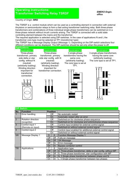
The TSRDF is a control module which can be used as a controlling element in connection with external<br />
thryistors or semiconductor relays to form a fast acting transformer switching relay. Both three-phase<br />
transformers and combinations of three individual single-phase transformers can be switched-on in a<br />
three-phase network without inrush currents arising. The TSRDF is connected with a solid state<br />
controlling element between the mains and the transformer.<br />
The required application is selected using DIP-switches. In the case of applications N and L the<br />
transformer core type must be selected at TP1 (transformer type)<br />
The TSRDF has a Message Display Output (Message 1). Depending on the DIP-switch selections four<br />
different conditions can be displayed. The DIP-switches should be set only when the power is off.<br />
Applications<br />
Application D<br />
Three-phase<br />
transformer, primary<br />
si<strong>de</strong> <strong>de</strong>lta or star<br />
config. without N<br />
(neutral)<br />
(arbitrarily loading).<br />
Winding direction<br />
important for<br />
transformer<br />
connection.<br />
Application S<br />
Three-phase<br />
transformer, primary<br />
si<strong>de</strong> star config. with N<br />
(neutral)<br />
(arbitrarily loading).<br />
Winding direction<br />
important for<br />
transformer connection.<br />
Application N<br />
3 single-phase<br />
transformers having the<br />
same core<br />
(arbitrarily loading).<br />
The core type is set at<br />
TP1.<br />
Application L<br />
3 single-phase transformers<br />
having the same core<br />
(arbitrarily loading).<br />
The core type is set at TP1.<br />
DIP-Switch:<br />
No. Function Position<br />
1 Error handling<br />
Off No automatic restart<br />
On Automatic restart after an error<br />
2 Rotation direction<br />
Off Switched-on for clockwise phase-sequence<br />
recognition On Switched-on for clockwise and anticlockwise phase-sequence<br />
3 Control input 1<br />
Off Control input enabled for external control signal<br />
(Remote-on input) On Switched-on without external control signal<br />
4 Control input 2<br />
Off Control input enabled for additional external control signal<br />
On Switched-on without external control signal<br />
5/6 Message Display 1 5 6 Function Message Display 1:<br />
Off Off Fully-on message<br />
On Off OK-Message<br />
Off On Error-message<br />
On On Bypass contactor control<br />
7/8 Applications<br />
7 8 Application type:<br />
Off Off D, Three-phase transformer, <strong>de</strong>lta or star config. without MP<br />
On Off S, Three-phase transformer, star configuration with MP<br />
Off On N, 3 Single phase transformer between phase and N<br />
On On L, 3 Single phase transformer between two phases<br />
TSRDF_oper_inst-<strong>emeko</strong>.doc 12.05.2011 EMEKO 1
Setting the premagnetisation on the trimming potentiometer <strong>de</strong>pending on transformer type:<br />
On the trimmer potentiometer TP1 the transformer core type of the single-phase transformer being used<br />
for application N or L must be set. For applications D and S the trimmer function does not apply.<br />
Toroidal core transformers:<br />
set to position R<br />
Coil form (shell) transformers (stack-core transformers):<br />
set to position P (factory setting)<br />
The correct position for stack-core transformers (P) can vary between the<br />
"10- and 2 o’clock " position.<br />
Strip-wound cut core transformers:<br />
Potentiometer setting between the "P" and "R" settings<br />
3. Messages:<br />
Message Display 1:<br />
The LED „Message Display 1“ (yellow) is illuminated, when the relay contact between the terminals 23<br />
and 24 is closed. The Message Display1 can be applied for various functions.<br />
„Fully-on-Message“ The relay contact is closed, as soon as the connected transformer has been fully<br />
switched-on by the TSRDF when the premagnetisation (remnance setting) is<br />
completed.<br />
„OK-Message“: The relay contact is closed after power is supplied to the TSRDF and initialisation<br />
is complete . On malfunction the contact is opened.<br />
„Error Message“: On malfunction the contact is closed.<br />
„Bypass-contactor The relay contact is used to control a bypass contactor, used to bridge the<br />
control“: control elements.<br />
OK- LED:<br />
The LED OK (green) is illuminated when the TSRDF is in the ‘OK’ status. Malfunctions are indicated by<br />
different flashing rates.<br />
Flashing Malfunction<br />
rate<br />
continuous OK- state<br />
10 Hz A remote-on signal has been applied, and no automatic resetting after malfunction<br />
(DIP1=Off)<br />
5 Hz Three-phase network is counter-clockwise, and switching-on only for clockwise phasesequence<br />
(DIP2=Off)<br />
1 Hz The supply voltage is outsi<strong>de</strong> the limiting voltage values (-20/+15% of Urated)<br />
10 Hz Internal error<br />
4. Additional Information:<br />
Bypass-Contactor:<br />
To protect the safety coil it is recommen<strong>de</strong>d to connect an RC-element parallel to the coil.<br />
General safety instructions:<br />
The TSRDF should be installed and connected without applied voltage only by trained electrotechnical<br />
personnel. In addition initial operation and commissioning should also be carried out only by suitably<br />
trained electrotechnical personnel.<br />
Potential separation does not occur during switching of the TSRDF as additional RC elements are<br />
connected between the input and the output thyristor clips.<br />
Emeko Ing. Büro, M Konstanzer<br />
Customer care – Application- Marketing<br />
Britzingerstr. 36<br />
D 79114 Freiburg<br />
Telefon: 0(049)170/2410655<br />
Telefax: 0(049)761/441888<br />
e-mail: Emeko@t-online.<strong>de</strong><br />
Internet: http://www.<strong>emeko</strong>.<strong>de</strong><br />
FSM Elektronik GmbH<br />
Development – Production – Sales<br />
Scheffelstr. 49<br />
D 79199 Kirchzarten<br />
Telefon: 0(049)7661/9855-0<br />
Telefax: 0(049)7661/985511<br />
e-mail: info@fsm-elektronik.<strong>de</strong><br />
Internet: http://www.fsm-elektronik.<strong>de</strong><br />
TSRDF_oper_inst-<strong>emeko</strong>.doc 12.05.2011 EMEKO 2
<strong>Operating</strong> <strong>Instructions</strong>:<br />
<strong>Transformer</strong> <strong>Switching</strong> <strong>Relay</strong> TSRDF<br />
TSRDF connection diagram for external Thyristors<br />
Emeko engineering<br />
office<br />
TSRDF_oper_inst-<strong>emeko</strong>.doc 12.05.2011 EMEKO 3
TSRDF connection diagram for external semiconductor relays<br />
FSM Elektronik GmbH<br />
Development – Production – Sales<br />
Scheffelstr. 49<br />
D 79199 Kirchzarten<br />
Telefon: 0(049)7661/9855-0<br />
Telefax: 0(049)7661/985511<br />
e-mail: info@fsm-elektronik.<strong>de</strong><br />
Internet: http://www.fsm-elektronik.<strong>de</strong><br />
Emeko Ing. Büro, M.Konstanzer<br />
Customer care – Applications - Marketing<br />
Britzingerstr. 36<br />
D 79114 Freiburg<br />
Telefon: 0(049)170/2410655<br />
Telefax: 0(049)761/441888<br />
e-mail: Emeko@t-online.<strong>de</strong><br />
Internet: http://www.<strong>emeko</strong>.<strong>de</strong><br />
TSRDF_oper_inst-<strong>emeko</strong>.doc 12.05.2011 EMEKO 4
<strong>Operating</strong> <strong>Instructions</strong>:<br />
RCP Board for Thyristors<br />
EMEKO Engineering<br />
Office<br />
The RC-element and die Gate-catho<strong>de</strong>-wiring for a thyristor module or two antiparallel<br />
connected thyristors are present on the RCP-printed circuit board as control elements.<br />
Thus a thyristor module or two antiparallel connected thyristors either TSRLF or TSRDF<br />
can be controlled. Spring reversal clips are used on the RCP printed circuit board<br />
(clamping area 0.1–2mm 2 ).<br />
FSM Elektronik GmbH<br />
Development – Production – Sales<br />
Scheffelstr. 49<br />
D 79199 Kirchzarten<br />
Telefon: 0(049)7661/9855-0<br />
Telefax: 0(049)7661/985511<br />
e-mail: info@fsm-elektronik.<strong>de</strong><br />
Internet: http://www.fsm-elektronik.<strong>de</strong><br />
Emeko Ing. Büro, M.Konstanzer<br />
Customer Care – Applications -- Marketing<br />
Britzingerstr. 36<br />
D 79114 Freiburg<br />
Telefon: 0(049)170/2410655<br />
Telefax: 0(049)761/441888<br />
e-mail: Emeko@t-online.<strong>de</strong><br />
Internet: http://www.<strong>emeko</strong>.<strong>de</strong><br />
TSRDF_oper_inst-<strong>emeko</strong>.doc 12.05.2011 EMEKO 5