Create successful ePaper yourself
Turn your PDF publications into a flip-book with our unique Google optimized e-Paper software.
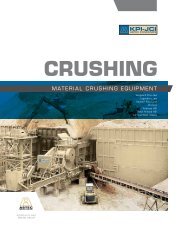
Kolberg-Pioneer, Inc.Johnson Crushers Intranational, Inc.Astec Mobile Screens, Inc.<strong>KPI</strong>-<strong>JCI</strong> and Astec Mobile Screens represents theonly lines of Crushing, Screening, Material Handling,Washing, Classifying and Feeding equipment andsystems designed, manufactured and supported in theU.S.A., and backed by authorized dealers worldwide.<strong>KPI</strong>-<strong>JCI</strong> and Astec Mobile Screens continues tolead the industry with tomorrow’s technology deliveringthe right equipment and systems today to meet yourapplication and production needs of tomorrow. Fromconcept to production, innovative products to worldclasssupport, <strong>KPI</strong>-<strong>JCI</strong> and its distributors offer you themost experienced team in the industry ready to offeryou simple and profitable solutions that meet all yourobjectives PROFITABILITY!<strong>KPI</strong>-<strong>JCI</strong> and Astec Mobile Screens is Your OneSource supplier for all your aggregate, recycle andre-mediation needs.
FIFTH EDITION<strong>KPI</strong>-<strong>JCI</strong> and Astec Mobile Screens is a worldwideand industry leader for bulk material handlingand processing equipment including; conveyors,screening plants, pugmill plants, sand and aggregatewashing/classifying systems and all types of mobile,portable and stationary aggregate processingplants for the aggregate, recycle and constructionindustries.<strong>KPI</strong>-<strong>JCI</strong> and Astec Mobile Screens has made everyeffort to present the information contained in thisbooklet accurately. However, the information shouldbe a general guide and <strong>KPI</strong>-<strong>JCI</strong> and Astec MobileScreens does not represent the information as exactunder all conditions. Because of widely-varying fieldconditions and characteristics of material processed,information herein covering product capacities andgradations produced are estimated only.Products of <strong>KPI</strong>-<strong>JCI</strong> and Astec Mobile Screensare subject to the provisions of their standardwarranty. All specifications are subject to changewithout notice.© <strong>KPI</strong>-<strong>JCI</strong> 3.5M pg 08/14 Printed in U.S.A.
FORWARDAggregate production is based on mathematicalrelationships, volumes, lengths, widths, heights andspeeds. Because of widely-varying field conditionsand characteristics of material processed,information herein relating to machine capacitiesand gradations produced are estimates only. Muchof this data of special interest to producers andtheir employees has been included in this valuablebooklet. We at <strong>KPI</strong>-<strong>JCI</strong> and Astec Mobile Screenshope you find this resource a valuable tool in yourorganization and operations.Count on us to be your supplier for all youraggregate, recycle and construction needs.2
12FIGURE NO. 13RELATIVE WORLD PRODUCTIONBY VALUESand and gravel, and crushed stone, arethe number one and two ranked mineralresources (exclusive of energy resources)worldwide in terms of both amountand value.Courtesy ofUSGSModified after Lawatscheck, 1990456
4TABLE OF CONTENTSAngle of Repose/Surcharge.................................................... 191Autogenous Crushing...........................................................74, 81Belt Speed.................................................................................. 196Blade Mills.......................................................................... 105-106ClassifyingControls (Spec-Select I, II and III)...................................124-125Introduction............................................................................. 107Pipes, Velocity Flow and Friction Loss.................................... 120Tanks...............................................................................119-123Weir Flow....................................................................... 123, 213Coarse Material Washing................................................100-106CrushersConesKodiak Series......................................................... 33, 34-56LS Series................................................................ 33, 57-64Horizontal Shaft Impactors (HSI)Andreas style......................................................... 28, 31-32New Holland style.................................................. 28, 29-30Jaws.................................................................................... 22-27Rolls.................................................................................... 65-72Vertical Shaft Impact crushers (VSI)................................... 73-81Crusher notesKodiak and LS Series................................................................ 34Vertical Shaft Impactor (VSI).............................................. 74, 81DataAngle of repose – surcharge................................................... 191Belt carrying capacity.............................................................. 188Belt speeds..................................................................... 189, 193Calculations....................................................................... 193Elevation, conveyors.......................................................181-184Horsepower requirements...............................................191-192Idler classification.................................................................... 182Incline, bulk materials, recommended..................................... 180StockpileCircular.............................................................................. 186Conical.............................................................................. 185Extendable stacker............................................................ 200Volume.............................................................................. 187Weights, common materials............................................223-225Weir flow......................................................................... 123, 213Data, Industry Terms and Definitions............................241-246Dredge pump........................................................................... 210Electric motors and wiring...............................................205-209
Generator sizing...................................................................... 209Pipes, velocity flow and friction loss................................211-212Railroad ballast........................................................................ 203Riprap...................................................................................... 204Spray nozzles..................................................................214-218Weights and measurers..................................................219-225Definitions and Terms...................................................... 241-246Fine Material Washing......................................................107-112FM (Fineness Modulus)............................................................. 99FRAP......................................................................... 167-179General Information on the Aggregate Industry............ 3, 8-11GradationsAggregates..............................................................13-15, 94-95ASTM C-33, C-144.............................................................. 94-98Hoppers..........................................................................................17Horizontal Shaft Impactors (HSI)Andreas style................................................................ 28, 31-32New Holland style......................................................... 28, 29-30Material Handling.............................................................. 180Belt speeds.............................................................188-189, 193Recommended by material............................................... 189Calculations....................................................................... 187Capacity, belt........................................................................... 188Elevation..........................................................................183-184Horsepower requirements...............................................191-192Idler classification.................................................................... 182Incline bulk materials, recommended...................................... 180Models, sizes and selections...........................................194-201Pugmills....................................................................................... 202Screening and Washing Plants......................................126-127Screens, calculating area VSMA............................................ 147Screens, TypesHorizontal..............................................143-144, 148, 159-162Incline.............................................................141-142, 148-157Multi-Slope (Combo)......................................144-145, 163-165High Frequency.................................................................132-139Sieve sizes.......................................................................... 94-99SE (Sand Equivalent test)......................................................... 99Sieve sizes...............................................................................12-13Spray nozzles.....................................................................214-217StockpileAngle of Repose/Surcharge.................................................... 191Circular.................................................................................... 187Conical.................................................................................... 185Extendable Stacker................................................................. 2005
Volume.................................................................................... 187Terms and Definitions...................................................... 241-246Track Mounted PlantsFast Trax ® Screen Plants.......................................................... 82Fast Trax ® High Frequency Screen Plants................................ 83Fast Trax ® Jaw Plants............................................................... 84Fast Trax ® Kodiak Plus Cone Plants......................................... 85Fast Trax ® Impactor Plants........................................................ 86Global Track Screening Plants.................................................. 87Global Track Direct Feed Plants............................................... 88Global Track Jaw Plants............................................................ 89Global Track Kodiak Plus Cone Plants..................................... 90Global Track Conveyors............................................................ 91Typical Gradation CurveGravel Deposit............................................................................14Limestone Quarry Run...............................................................15Washing Introduction............................................................ 92-93ASTM C-33, C-144.............................................................. 96-98Blade Mills...................................................................... 105-106Classifying.......................................................................107-125Coarse material washing................................................ 100-106Controls...........................................................................124-125Dredge pump........................................................................... 210Fine material washing.....................................................107-112Fineness Modulus (FM).......................................................... 101Log Washers.................................................................. 101-102Sand Equivalent test (SE)......................................................... 99Series 9000 Dewatering Screen..................................... 128-129Series 9000 Plants................................................................. 130Screening and Washing plants........................................126-127Weights and Measures....................................................218-240World Production........................................................................... 36
NOTES:7
GENERAL INFORMATION ON THE INERTMINERAL (AGGREGATE) INDUSTRYModern civilization is based on the use of inert mineralsfor concrete and asphaltic products. In truth, aggregateproduction is the largest single extractive industry in theUnited States. In excess of 2.8 billion tons of sand, graveland crushed rock are produced annually. Because aggregatesplay such a vital role in the continuing growth ofthe nation and the world, demand for all types can beexpected to increase substantially in the years ahead.There is great romance about these commonplace minerals;the earth sciences tell us a compelling story of theevolution of the earth’s mantle and its minerals which manhas found so valuable to the civilizing processes on hisplanet. Since the earliest Ice Age, erosion of the continentalrock by earth, wind, rain and fire has resulted infractions being carried down the mountains by wind andwater, the grains settling in an almost natural grading process.Other natural events such as floods and upheavalscaused rivers and streams to change courses, buryingriver beds that have become high production sand andgravel operations in our time. Evaporation, condensation,precipitation and chemical actions, percolation and fusionshave formed other rock materials that have become valuableaggregates in modern times. Advancements ingeology and technology aid the industry in its progress togreater knowledge about these building blocks of all agesand civilizations.Locating these minerals has become much easier, too—and just in time, as recently the nation has acknowledgedthe state of neglect of hundreds of thousands of miles ofstate and county roads. The massive interstate programhas dominated the expenditure of roadbuilding funds atthe expense of these rural highways, so that today thereare vast amounts of repair, reclamation and replacementof roads to be done. And, of course, locating nearbysources of roadbed materials wherever possible will affectthe economy of construction, and in some cases, even thekind of construction as well.8
Rapid field investigations for possible sources of mineralshave been made very simple and relatively inexpensiveby the use of portable seismic instruments and earthresistivity meters. The latter are especially effective inlocating sand, gravel and ground water by measuring theinherent electrical characteristics of each. Briefly, an alternatingcurrent is applied across electrodes implanted atknown spacings in the surface soil; the potential drop ofthe current between the electrodes indicates whether thesubsurface geology includes any high resistance areas,indicating sand, gravel or water. Another tool, the portableseismic instrument, is used to measure the velocityof energy transmitted into the earth as deep as 1,000feet. The velocity of the energy wave’s travel through thesubsurface geologic structure indicates the density orhardness of each layer or strata. For example, the velocityof topsoil may be 3,000 feet per second while limestone,granite and other potentially useful inert materials mayhave velocities beyond 12,000 feet per second. Thus,where the occurrence of aggregate material is not alwaysconvenient to the shortest haul routes or major populationcenters, locating and utilizing them have benefittedgreatly by modern technology.CLASSES OF AGGREGATESThere are two main classes of aggregates.1. Natural aggregates in which forces of nature haveproduced formations of sand and gravel deposits.These may include silts, clays or other foreignmaterials which are difficult to reject. Further, gradationsmay be quite different than those requiredfor commercial sales. To meet such requirements, itbecomes necessary to process or beneficiate naturalaggregate deposits.2. Manufactured aggregates are obtained fromdeposits or ledges of sedimentary rock (formed bysediments) or from masses of igneous rock (formedby volcanic action or intense heat). These areblasted, ripped or excavated and then crushed andground to specified gradations. These deposits, too,may include undesirable materials such as shales,slates or bodies of metamorphic or igneous rock.Such deleterious materials must be removed in theprocessing operations.9
PROCESSING OF AGGREGATESMuch of the equipment used in the processing of rawaggregates has been adapted from other mineral processingtechniques and modified to meet the specificrequirements of the crushed stone, sand and gravelindustry. Other types of equipment have been introducedto improve efficiency and final product. The equipment isclassified in four groups.1. Reduction equipment: Jaw, cone, roll, gyratory,impact crushers and mills; these reduce materialsto required sizes or fractions.2. Sizing equipment: Vibratory and grizzly screens toseparate the fractions in varying sizes.3. Dewatering equipment: Sand sorters, log washers,sand and aggregate preparation and fine andcoarse recovery machines.4. Sorting equipment. This can include various kindsof feeder traps and conveyor arrangements totransfer, stockpile or hold processed aggregates.As to method, there are two types of operations at mostsand and gravel pits and quarry operations. They include:1. Dry process: Here, the material is excavated bymachines or blasted loose and is hauled to a processingplant without the use of water.2. Wet process: This may involve pumping (dredgepumps) or excavation (draglines) of the aggregatematerial from a pit filled with water. The materialenters the processing operation with varying quantitiesof water.The ideal gradation is seldom, if ever, met in naturallyoccurring sand or gravel. Yet the quality and control ofthese gradations is absolutely essential to the workabilityand durability of the end use.The aggregate has three principal functions:1. To provide a relatively cheap filler for cementing orasphaltic materials.2. To provide a mass of particles that will resist theaction of applied loads, abrasion, percolation ofmoisture and water.3. To keep to a minimum the volume changes resultingfrom the setting and hardening process andfrom moisture changes.10
The influence of the aggregate on the resulting productdepends on the following characteristics:1. The mineral character of the aggregate as related tostrength, elasticity and durability.2. The surface characteristics of the particles, particularlyas related to workability and bonding within ahardened mass.3. Aggregate with rough surfaces or angular shapesdoes not place or flow as easily into the forms assmooth or rounded grains.4. The gradation of the aggregates, particularly asrelated to the workability, density and economy ofthe mix.Of these characteristics, the first two are self-explanatoryand inherent to a particular deposit. In some cases, anaggregate can be upgraded to an acceptable product byremoving unsound or deleterious material, using beneficationprocesses.Gradation, however, is a characteristic which can bechanged or improved with simple processes and is theusual objective of aggregate preparation plants.11
100SIEVE ANALYSIS ENVELOPEPercent passing by weight80604020Nos 100-4 sievesNos 4-1.5 in. sieves0100 50 30 16 8 4 3 /8 1 /2 3 /4 1 1 / 2Standard sizes of square-mesh sievesCurves indicate the limits specified in ASTM for fine and coarse aggregateFIGURE NO. 2EXAMPLE OF ALLOWABLE GRADATION ZONEIMPORTANCE OF GRADATION—CONCRETETo improve workability of concrete, either the amount ofwater or the amount of fine particles must be increased.Since the water-to-cement ratio is governed by thestrength required in the final cured concrete, any increasein the amount of water would increase the amount ofcement in the mix. Since cement costs are much greaterthan aggregate, it is evident that varying the gradation ismore economical. Most of the formula used for proportioningthe components of the concrete have been worked outas the results of actual experimentation. They are based,however, on two fundamentals.1. To obtain a sound concrete, all voids must be filledeither with fine aggregates or cement paste.2. To obtain a sound concrete, the surface of eachaggregate particle should be covered with cementpaste.An ideal mix is a balance between saving on cementpaste by using fine aggregates to fill the voids, and theadded paste required to cover the surfaces of these additionalaggregate particles.12
ACTUAL GRADATIONThe ideal gradation is seldom, if ever, met in naturallyoccurringsand or gravel. In practice, the quality of thegradation of the aggregate, the workability of the concrete,cement and asphalt requirements must be balanced toachieve strength and other qualities desired, at minimumtotal cost.Sizing of material larger than No. 8 sieve is best and mosteconomically done by the use of mechanical screens ofvarious types, either dry or wet. In actual practice, however,the division between coarse aggregates, whichrequire different equipment for sizing, is set at No. 4 sieve(Fig. 3).Percent Weight RetainedSieve Allowable Sample TestedNo.Cumulative Individual CumulativeMin. Max.3 ⁄8” 0 0 0 04 0 10 4 48 10 35 11 1516 30 55 27 4230 55 75 28 7050 80 90 18 88100 92 98 8 96Pan 100 100 4 100FIGURE NO. 3Tables have been published to facilitate these calculations,and they are based on the maximum size of the coarseaggregate which can be used for the specific type of constructionplanned.13
inchesTYPICAL GRADATION CURVESFOR GRAVEL DEPOSITSSIEVE ANALYSIS% RETAINEDmm0 20 40 60 80 100615251274102376.221-1/21-1/413/41/23/450.838.131.825.419.012.79.53SIEVE SIZE1/4#4#8#106.35#16#20#30#40#50#60#80#100KEY:35/65 Heavy Gravel50/50 Deposit65/35 Heavy Sand#2001008060 40% PASSING20014
TYPICAL GRADATION CURVESFOR LIMESTONE QUARRY RUN15
APRON FEEDERSParticularly suited for wet, sticky materials, the Apron Feederprovides positive feed action while reducing material slippage.Feeder construction includes heavy-duty and extra-heavy-dutydesigns, depending upon the application.16
STANDARD HOPPER APPROXIMATE CAPACITIES—APRON FEEDERS6 Ft 1.83 m 8 Ft. 2.44 m 10 Ft. 3.05 m 12 Ft. 3.66 m 14 Ft. 4.27 mWidth Yd. 3 m 3 Yd. 3 m 3 Yd. 3 m 3 Yd. 3 m 3 Yd. 3 m 330” ( 762 mm) Apron Feeder Without Extension 2.1 1.6 3.2 2.4 4.3 3.3 5.4 4.1 — —30” ( 762 mm) Apron Feeder With Extension 3.3 2.5 5.8 4.4 8.3 6.4 10.8 8.2 — —36” ( 914 mm) Apron Feeder Without Extension 2.4 1.8 3.6 2.8 4.8 3.7 6.0 4.6 7.2 5.536” ( 914 mm) Apron Feeder With Extension 3.6 2.8 6.3 4.8 9.0 6.9 11.7 8.9 14.5 11.142” ( 1067 mm) Apron Feeder Without Extension 2.6 2.0 3.9 3.0 5.3 4.0 6.6 5.0 7.9 6.042” ( 1067 mm) Apron Feeder With Extension 3.9 3.0 6.8 5.2 9.7 7.4 12.6 9.6 15.6 11.848” ( 1219 mm) Apron Feeder Without Extension — — 4.4 3.4 5.8 4.4 7.3 5.6 8.8 6.748” ( 1219 mm) Apron Feeder With Extension — — 7.4 5.6 10.5 8.0 13.6 10.4 16.7 12.8RECIPROCATING PLATE FEEDERSModel Size Type of Approx. Capacity* Hopper Size Hopper Capacity WeightNumber in. mm Service at 60 RPM Ft. Sq. Meters Sq. Cu. Yards Cu. Meters (With Hopper)25 RP 24 610 Standard 100-200 TPH ( 90.7 - 181 mt/h) 6 1.83 1.7 1.3 2050 lbs. 931 kg31 RP 30 762 Standard 150-300 TPH ( 136-272 (mt/h) 6 1.83 1.7 1.3 2165 lbs. 983 kg30 RP 30 762 Heavy Duty 150-300 TPH ( 136-272 mt/h) 6 1.83 1.7 1.3 2550 lbs. 1158 kg37 RP 36 914 Standard 215-430 TPH ( 195-390 mt/h) 7 2.14 2.6 1.99 3175 lbs. 1441 kg36 RP 36 914 Heavy Duty 215-430 TPH ( 195-390 mt/h) 7 2.14 2.6 1.99 3950 lbs. 1793 kg42 RP 42 1067 Heavy Duty 300-600 TPH ( 272-544 mt/h) 7 2.14 2.6 1.99 4710 lbs. 2136 kgNOTE: *Range is for type of feed from damp sticky to dry material.17
APPROXIMATE PER HOUR CAPACITIES OF APRON FEEDERS ACCORDING TO WIDTH1830” Wide 36” Wide 42” Wide 48” Wide 60” Wide 72” Wide3Tons Yds3 Ton Yds3 Tons Yds3 Tons Yds3 Tons Yds3 TonsPan Travel(Ft. per Min.) Yds10 55 74 80 108 109 147 143 192 222 300 320 43215 83 112 120 162 164 222 214 289 333 450 480 64820 110 148 160 216 218 294 284 384 444 600 650 86425 138 186 200 270 273 369 357 482 555 750 800 108030 165 223 240 324 327 442 427 577 667 900 960 129635 193 260 280 378 382 516 500 673 778 1050 1120 151240 220 296 320 432 436 588 572 768 888 1200 1280 1728NOTE: Considerable variance will always be encountered when calculating the capacities of feeders. Usually, experience is the best guide to what a feeder will handle under given conditions of material, rate of travel of the feeder pans, anddepth of loading. The table above is based on a depth of material equal to half the feeder width, and tons are based on material weighing 2,700 pounds per cu. yd. A feeding factor of .8 has been introduced to compensate for voids,resistance to flow, etc. This factor, too, will vary with the type of material and its condition when fed.The following formula can be used to calculate the approximate capacity in cubic yards of a feeder of given width where the feeding factor is determined to be other than .8:Cu. Yds per Hr. = 2.22 (d x w x s x f); whered = depth of load on feeder, in feet: s = rate of pan travel, in feet per minute;w = width of feeder, in feet; f = feeding factor.To convert cu. yds. to tons; multiply cu. yds. by 1.35.Pan Travel (meters per.762 m Wide .914 m Wide 1.07 m Wide 1.22 m Wide 1.52 m Wide 1.83 m Wide(minute) m 3 mt m 3 mt m 3 mt m 3 mt m 3 mt m 3 mt3.05 42 67 61 98 83 133 109 174 170 272 245 3924.57 63 102 92 147 125 201 164 262 254 408 367 5886.10 84 134 122 196 167 267 217 348 339 544 489 7847.62 105 169 153 245 209 335 273 437 424 680 611 9089.14 126 202 183 293 250 401 326 523 510 816 734 117610.67 147 236 214 343 292 468 382 610 594 953 856 137212.19 168 269 245 392 333 533 437 697 679 1089 978 1568
VIBRATING FEEDERSDesigned to convey material while separating fines,Vibrating Feeders provide smooth, controlled feed ratesto maximize capacity. Grizzly bars are tapered to selfrelievewith adjustable spacing for bypass sizing. Feederconstruction includes heavy-duty deck plate with optionalAR plate liners. Heavy-duty spring suspension withstandsloading impact and assists vibration.Scalping Area =SCALPING SCREEN SIZING FORMULATons / hour of undersize in the feedCapacity per square feet (“C”) x modifying factors “O” and “F”CAPACITY FACTOR “C”FACTOR “C”SIZE OF OPENING (IN.) PERFORATED PLATE GRIZZLY BARS2 4.1 6.13 5.4 8.14 6.7 10.05 8.6 15.06 9.8 17.27 10.9 19.18 11.6 23.29 12.5 25.010 13.5 27.0MODIFYING FACTOR “O” FOR PERCENTOF OVERSIZE IN THE FEED% FACTOR10 1.0520 1.0130 .9840 .9550 .9060 .8670 .8080 .7085 .6490 .55MODIFYING FACTOR “F” FOR PERCENTPASSING HOLES HALF-SIZE OF OPENING% FACTOR10 .5520 .7030 .8040 1.0050 1.2060 1.4070 1.8080 2.2085 2.5090 3.0019
VIBRATING FEEDERS—APPROXIMATE CAPACITY*30” (.76m) 36” (.91m) 42” (1.07m) 50” 1.27m) 60” (1.5m)WIDE WIDE WIDE WIDE WIDERPM TPH mt/h TPH mt/h TPH mt/h TPH mt/h TPH mt/h600 828 754650 623 568 898 818700 315 287 473 431 671 611 967 881750 270 246 337 307 507 462 720 656 1035 943800 290 264 360 328 541 493 767 698850 305 278 382 348 575 524900 325 296 404 368 609 555950 345 314 427 389 642 5851000 365 332CAPACITY MULTIPLIERS FOR VARIOUS FEEDER PANMOUNTING ANGLES FROM 0° TO 10° DOWN HILL—ALL VIBRATING FEEDERSAngle Down Hill 0° 2° 4° 6° 8° 10°Multiplier 1.0 1.15 1.35 1.6 1.9 2.25NOTE: *Capacity can vary ±25% for average quarry installations—capacity will usually begreater for dry or clean gravel. Capacity will be affected by the methods of loading,characteristics and gradation of material handled, and other factors.(4° and more consult with Factory)STANDARD HOPPER APPROXIMATE CAPACITIESVIBRATING FEEDERSStandard Feeder Size Yds. 3 M 330” x 12’ ( 762mm x 3.7m) Without Extension 5.5 4.230” x 12’ ( 762mm x 3.7m) With Extension 7.2 5.536” x 14’ ( 914mm x 4.3m) Without Extension 7.2 5.536” x 14’ ( 914mm x 4.3m) With Extension 12.6 9.636” x 16’ ( 914mm x 4.9m) Without Extension 8.2 6.336” x 16’ ( 914mm x 4.9m) With Extension 14.4 11.042” x 15’ (1067mm x 4.6m) Without Extension 9.0 6.942” x 15’ (1067mm x 4.6m) With Extension 18.0 13.842” x 17’ (1067mm x 5.2m) Without Extension 10.2 7.842” x 17’ (1067mm x 5.2m) With Extension 20.4 15.642” x 18’ (1067mm x 5.5m) Without Extension 10.0 8.242” x 18’ (1067mm x 5.5m) With Extension 21.6 16.542” x 20’ (1067mm x 6.2m) Without Extension 12.0 9.242” x 20’ (1067mm x 6.2m) With Extension 24.0 18.450” x 16’ (1270mm x 4.9m) Without Extension 11.0 8.450” x 16’ (1270mm x 4.9m) With Extension 21.6 16.550” x 18’ (1270mm x 5.5m) Without Extension 12.6 9.650” x 18’ (1270mm x 5.5m) With Extension 24.3 18.650” x 20’ (1270mm x 6.1m) Without Extension 14.0 10.750” x 20’ (1270mm x 6.1m) With Extension 27.0 20.660” x 24’ (1524mm x 7.3m) Without Extension 19.6 15.060” x 24’ (1524mm x 7.3m) With Extension 43.0 32.920
BELT FEEDER CAPACITY (TPH)Crushin g24” BELT FEEDER(W = 18”)30” BELT FEEDER(W = 24”)36” BELT FEEDER(W = 30”)42” BELT FEEDER(W = 36”)H (inches)Belt Speed FPM10 20 30 40 50 608 30 60 90 120 150 1809 34 68 101 135 169 20310 38 75 113 150 188 22511 41 83 124 168 206 24812 45 90 135 180 225 27013 49 98 146 195 244 29314 53 105 158 210 262 3158 40 80 120 160 200 2409 45 90 135 180 225 27010 50 100 150 200 250 30011 55 110 165 220 275 33012 60 120 180 240 300 36013 65 130 195 260 325 39014 70 140 210 280 350 4208 50 100 150 200 250 3009 56 113 169 225 281 33810 62 125 187 250 312 37511 69 137 206 275 344 41212 75 150 225 300 375 45013 81 162 244 325 406 48714 87 175 262 350 437 5258 60 120 180 240 300 3609 68 135 203 270 338 40510 75 150 225 300 375 45011 83 165 248 330 413 49512 90 180 270 360 450 54013 98 195 293 390 488 58514 105 210 315 420 525 630NOTE: Capacities based on 100 lb./cu. ft. materialTPH = 3 x H (in.) x W (in.) x FPM14421
LEGENDARY JAW CRUSHERCrushin gFor almost a century, Legendary Jaw Crushers havebeen processing materials without objection. Used mostcommonly as a primary crusher — but also as a secondaryin some applications — these compression crushersare designed to accept all manner of materials includinghard rock, gravels and recycle pavements, as well asconstruction and demolition debris.23
Crushin gTestJAW CRUSHERSAPPROXIMATE JAW CRUSHERS GRADATIONOPEN CIRCUITAPPROXIMATE GRADATIONS AT PEAK TO PEAK CLOSED SIDE SETTINGSSieve 3 ⁄4” 1” 1 1 ⁄4” 1 1 ⁄2” 2” 2 1 ⁄2” 3” 3 1 ⁄2” 4” 5” 6” 7” 8” SieveTestSizes 19 25.4 31.8 38.1 50.8 63.5 76.2 89.1 102 127 152 178 203 Sizes(in.) mm mm mm mm mm mm mm mm mm mm mm mm mm (mm)12” 100 98 95 30510” 100 97 95 90 2548” 100 96 92 85 75 2037” Values Are Percent Passing100 97 92 85 76 65 1786” 100 98 93 85 74 65 53 1525” 100 97 95 85 73 62 52 40 1274” 100 96 90 85 70 56 45 38 28 1023” 100 93 85 75 65 50 38 32 27 23 76.22 1 ⁄2” 100 95 85 73 62 52 38 31 24 22 17 63.52” 100 96 85 70 55 47 39 28 24 20 17 13 50.81 1 ⁄2” 100 93 85 67 49 39 33 27 21 18 15 13 10 38.11 1 ⁄4” 96 85 73 55 39 31 27 23 17 15 13 10 8 31.81” 85 69 55 40 29 24 20 17 14 12 10 8 6 25.43 ⁄4” 66 49 39 28 21 18 15 13 11 9 8 6 5 19.01 ⁄2” 41 29 24 19 14 12 10 9 7 6 6 5 4 12.73 ⁄8” 28 21 18 14 11 9 8 7 5 5 5 4 3 9.531 ⁄4” 18 14 12 10 7 7 6 5 4 4 4 3 2 6.35#4 12 10 9 7 5 5 4 4 3 3 3 2 1 #4#8 6 6 5 5 4 4 3 3 2 2 2 1 0.5 #8The chart on this page is particularly useful in determining the percentagesof various sized particles to be obtained when two or more crushers areused in the same setup. It is also helpful in determining necessary screeningfacilities for making size separations. Here is an example designed to helpshow you how to use the percentage charts:To determine the amount of material passing 1¼” (31.8 mm) when thecrusher is set at 2” (50.8 mm) closed side setting: find 2” (50.8 mm) at thetop, and follow down the vertical line to 1¼” (31.8 mm). The horizontal lineshows 39% passing…or 61% retained.24
LEGENDARY JAW CRUSHERS—HORSEPOWER REQUIRED AND APPROXIMATE CAPACITIES IN TPH10” 11” 12”APPROXIMATE CAPACITIES AT PEAK TO PEAK CLOSED SIDE SETTINGS (IN TPH)*3 ⁄4” 1” 11 ⁄ 4” 11 ⁄2” 2” 21 ⁄2” 3” 31 ⁄2” 4” 5” 6” 7” 8” 9”HPRequired(Minimum)SIZE19 25 32 38 51 64 76 89 102 127 152 178 203 228 254 279 304mm mm mm mm mm mm mm mm mm mm mm mm mm mm mm mm mmElect Diesel RPM1016 15 25 10 12 14 19 24 281024 25 40 290 15 18 22 29 36 441036 40 60 290 22 27 33 44 55 671047 110 29 36 44 59 73 891524 40 60 290 36 45 54 63 721536 75 110 290 54 68 81 95 109 1361654 125 175 290 81 102 122 142 163 2041830 60 90 275 61 74 86 98 1232036 100 140 275 109 124 139 156 1872436 100 150 260 123 136 153 171 205 239 2732148 125 170 260 145 165 186 207 2482649 150 190 165 188 211 235 2822854 200 250 260 213 241 268 323 378 4333042 150 190 260 200 223 268 313 3573163 200 250 290 330 370 450 530 610 6903350 200 250 275 302 350 407 465 5223546 200 250 235 275 302 350 407 465 5224248 250 310 225 324 376 438 500 562 625 688 752 875*************************NOTE: *Based on material weighing 2,700 lbs. per cubic yard. Capacity may vary as much as ±25%.**Larger settings may be obtained with other than standard toggle plate…consult Factory.***Legendary jaw sizes that are no longer standard production models.25Crushin g
Crushin gVANGUARD JAW CRUSHERToday’s hard rock producer requires more out of a jawcrusher. The producer requires massive crushing energyand hydraulic closed-side-setting adjustment to increaseproductivity and reduce downtime. Used most commonlyas a primary crusher — but also as a secondary in someapplications — these compression crushers are designedto accept all manner of materials including hard rock,gravels and recycle pavements, as well as constructionand demolition debris.26Vanguard Plus Jaw Crusher Animationhttp://youtu.be/DIwR7BZAnpg
VANGUARD JAW CRUSHERSHORSEPOWER REQUIRED AND APPROXIMATE CAPACITIES IN TPHSIZEHPRequired(Minimum)Elect Diesel RPMAPPROXIMATE CAPACITIES AT PEAK TO PEAK CLOSED SIDE SETTINGS (IN TPH)*3 ⁄4” 1” 11 ⁄ 4” 11 ⁄2” 2” 21 ⁄2” 3” 31 ⁄2” 4” 5” 6” 7” 8”9” 10” 11” 12”19 25 32 38 51 64 76 89 102 127 152 178 203 228 254 279 304mm mm mm mm mm mm mm mm mm mm mm mm mm mm mm mm mm2640 125 160 285133-175150-200171-225190-250228-3002650 150 190 260157-206179-235200-264223-294268-3533055 200 250 250252-331285-375317-418382-503447-589502-6603144 150 190 260201-265228-300254-334304-400354-466405-533**3165 200 250 250252-331290-381353-465436-574504-663580-764657-865**3352 200 250 225302-398342-450395-520460-605525-6914450 250 310 225NOTE: *Based on material weighing 2,700 lbs. per cubic yard. Capacity may vary with the material characteristics.**Larger settings may be obtained with other than standard toggle plate…consult Factory.402-529467-615545-718621-818698-919775-1020Crushin g27
Crushin gHSI PLANTSTrack-Mounted Andreas-StyleWheel-Mounted Andreas-StyleWheel-Mounted New Holland-Style28
PRIMARY IMPACT CRUSHERS(New Holland Style)Crushin gMaking a cubical product necessary for asphalt andconcrete specifications poses many equipment problemsfor the aggregate producer. Among these problems areabrasive wear, accessibility for hammer maintenanceor breaker bar changes and bridging in the crushingchamber.Impact crusher units are designed to help overcomeproblems faced by producers and at the same time toprovide maximum productivity for existing conditions.29
Crushin gPRIMARY IMPACT CRUSHERS(NEW HOLLAND STYLE)—APPROXIMATE PRODUCTGRADATION—OPEN CIRCUITTest3850 4654 6064TestSieveSieveSizes Normal Close Normal Close Normal Close Sizes(in.) Setting Setting Setting Setting Setting Setting (mm)6” Values are percent passing 100 1525” 100 97 100 1274” 100 98 100 90 98 1023” 96 100 89 96 75 89 76.22 1 ⁄2” 90 97 80 90 66 80 63.52” 77 89 67 77 56 67 50.81 1 ⁄2” 64 75 56 64 48 56 38.11 1 ⁄4” 57 67 50 57 43 50 31.81” 50 58 44 50 38 44 25.43⁄4” 41 47 37 41 31 37 19.11⁄2” 32 37 28 32 24 28 12.73⁄8” 26 30 23 26 19 23 9.531⁄4” 20 23 17 20 14 17 6.35#4 17 19 15 17 12 15 #4#8 12 14 10 12 8 10 #8#16 8 9 6 8 5 6 #16#30 5 6 4 5 3 4 #30#50 3 4 3 3 2 3 #50#100 2 3 2 2 1 2 #100Recommended HP Approx. Capacities*MaximumSize Electric Diesel TPH mt/h Feed Size3850 250-300 350-450 250-450 227-409 24”4654 300-400 450-600 400-750 364-682 30”6064 400-600 600-900 600-1200 545-1091 40”NOTE: *Capacity depends on feed size and gradation, type of material, etc.Approximate product gradation can be expected as shown on chart. Theproduct will vary from that shown depending on the size and type of feed,adjustment of lower breaker bar, etc.30
ANDREAS-STYLEIMPACT CRUSHERSCrushin gThese impact crushers are designed for recycling concreteand asphalt, as well as traditional aggregatecrushing applications. The Maximum Performance Rotor(MPR) offers the mass of a solid design with the clearancesof an open configuration.Andreas-Style HSI Animationhttp://youtu.be/1En-mdIjork31
Crushin gANDREAS IMPACT CRUSHERSHORIZONTAL SHAFT IMPACT CRUSHERRecommended HPApprox. Capacities*Size Electric Diesel TPH mt/h4233 100 165 up to 200 up to 1814240 150 190 up to 250 up to 2274250 200 265 up to 300 up to 2725260 - 3 bar 300 390 up to 450 up to 4085260 - 4 bar 300 390 up to 450 up to 408Maximum Feed Size**Size Recycle Limestone Hard RockMin Lower/Upper ApronSetting4233 24”x24”x12” up to 18” up to 16” 1” / 2”4240 27”x27”x12” up to 21” up to 18” 1” / 2”4250 30”x30”x12” up to 21” up to 21” 1” / 2”5260 - 3 bar 36”x36”x12” up to 24” up to 21” 1” / 2”5260 - 4 bar 36”x36”x12” up to 21” up to 18” 1” / 2”100%90%80%Approximate Output Gradations-Open CircuitAPRONS:Upper @ 4"Lower @ 2"8000 fpm% Cumulative Passing70%60%50%40%30%20%6500 fpm5250 fpmFEED10%0%50 mesh 8 mesh 1" 3" 10"12"NOTE: *Capacity depends on feed size and gradation, type of material, etc.** Limestone and hard rock feed sizes are based on secondaryapplications.32
CONE CRUSHERSCrushin gTrack-Mounted Kodiak PlusWheel-Mounted Kodiak PlusWheel-Mounted LS33
Crushin gKODIAK PLUS AND LS CONE CRUSHER NOTES1. Capacities and product gradations produced by conecrushers will be affected by the method of feeding,characteristics of the material fed, speed of themachine, power applied, and other factors. Hardness,compressive strength, mineral content, grain structure,plasticity, size and shape of feed particles, moisturecontent, and other characteristics of the material alsoaffect production capacities and gradations.2. Gradations and capacities shown are based on a typicalwell-graded choke feed to the crusher. Well-gradedfeed is considered to be 90%-100% passing the closedside feed opening, 40%-60% passing the midpoint ofthe crushing chamber on the closed side (average ofthe closed side feed opening and closed side setting),and 0-10% passing the closed side setting. Chokefeed is considered to be material located 360 degreesaround the crushing head and approximately 6” abovethe mantle nut.3. Maximum feed size is the average of the open sidefeed opening and closed side feed opening.4. A general rule of thumb for applying cone crushers isthe reduction ratio. A crusher with coarse style linerswould typically have a 6 to 1 reduction ratio. Thus, witha 3 ⁄4” closed side setting, the maximum feed would be6 x 3 ⁄4 or 4.5 inches. Reduction ratios of 8 to 1 may bepossible in certain coarse crushing applications. Fineliner configurations typically have reduction ratios of4:1 to 6:1.5. Minimum closed side setting may be greater than publishedsettings since it is not a fixed dimension. It willvary depending on crushing conditions, the compressivestrength of the material being crushed, and stageof reduction. The actual minimum closed side setting isthat setting just before the bowl assembly lifts minutelyagainst the factory recommended pressurized hydraulicrelief system. Operating the crusher at above thefactory recommended relief pressure will void the warranty,as will operating the crusher in a relief mode(bowl float).34
KODIAK PLUS ANDLS CONE CRUSHERSCrushin gKODIAK 300PLUS CONEKODIAK 500PLUS CONE1400 LS ConeKodiak Plus Cone Crusher Animationhttp://youtu.be/DEg97HrBzeE35
Crushin gKODIAK OPERATING PARAMETERSThe following list outlines successful operating parametersfor the Kodiak Plus line of crushers. These are notprioritized in any order of importance.Material1. Material with a compressive strength greater than40,000 pounds per square inch should be reviewedand approved in advance by the factory.2. No more than 10% of the total volume of feed materialis sized less than the crusher closed side setting.3. The crusher feed material conforms to the recommendedfeed size on at least two sides.4. Moisture content of material below 5%.5. Feed gradation remains uniform.6. Clay or plastic material in crusher feed is limited toprevent the formation of compacted material or “pancakes”being created.Mechanical1. Crusher operates at factory recommended tramp ironrelief pressures without bowl float.2. Crusher support structure is level and evenly supportedacross all four corners. In addition, the supportstructure provides adequate strength to resist staticand dynamic loads.3. Crusher is operated only when all electrical, lubricationand hydraulic systems are correctly adjusted andfunctioning properly.4. Lubrication low flow warning system functions correctly.5. Lubrication oil filter functions properly and showsadequate filtering capacity on its indicator.6. Crusher drive belts are in good condition and tensionedto factory specifications.7. Crusher lubrication reservoir is full of lubricant thatmeets factory required specifications.8. Any welding on the crusher or support structure isgrounded directly at the weld location.9. Crusher input shaft rotates in the correct direction.10. Manganese wear liners are replaced at the end oftheir expected life and before coming loose or developingcracks.36
11. Crusher cone head is properly blocked prior to transport.12. Only authorized OEM parts or factory-approved wearparts are used.Application1. Reduction ratio limited to 6 to 1 below 1” closed sidesetting and 8 to 1 above 1” closed side setting providedno bowl float occurs.2. Manganese chamber configuration conforms to thefactory recommended application guidelines.3. Crusher is operated at the factory recommendedRPM for the application.4. Crusher feed is consistent, providing an even flow ofmaterial, centered in the feed opening, and coveringthe mantle nut at all times.5. Crusher input horsepower does not exceed factoryspecifications.6. Crusher discharge chamber is kept clear of materialbuildup.7. If the crusher cannot be totally isolated from metal inthe feed material, a magnet should be used over thecrusher feed belt.8. Crusher is never operated at zero closed side setting.Crushin g37
Crushin gProductSizeKODIAK 200 PLUS CONE CRUSHERGRADATION CHARTCrusher Closed Side Setting5 ⁄16” 3 ⁄8” 7 ⁄16” 1 ⁄2” 5 ⁄8” 3 ⁄4” 7 ⁄8” 1” 1 1 ⁄4” 1 1 ⁄2” 1 3 ⁄4” 2”7.94 9.52 11.11 12.7 15.87 19.05 22.22 25.4 32 38.1 44.5 50.8mm mm mm mm mm mm mm mm mm mm mm mm4” 1003 1 ⁄2” 100 963” 100 95 902 3 ⁄4” 98 92 862 1 ⁄2” 100 95 88 812 1 ⁄4” 97 91 83 742” 100 94 86 76 651 3 ⁄4” 100 97 88 79 66 551 1 ⁄2” 100 95 91 80 68 56 451 1 ⁄4” 100 97 90 83 70 56 46 381” 100 99 90 82 72 58 45 36 297⁄8” 100 99 93 86 74 64 48 38 30 253⁄4” 100 97 94 87 80 65 54 40 32 26 215⁄8” 98 94 87 80 69 55 46 34 28 22 181⁄2” 100 95 88 80 69 58 47 39 28 23 19 163⁄8” 91 84 73 63 52 44 37 28 21 17 14 125⁄16” 85 74 63 54 46 37 31 25 19 15 13 101⁄4” 74 61 50 44 36 32 26 21 16 13 11 94M 58 48 42 35 32 26 21 18 14 11 9 75⁄32” 50 41 36 30 28 23 18 15 12 10 8 68M 40 35 30 26 24 20 16 12 9 7 5 410M 35 31 26 22 20 18 14 10 8 6 4 316M 28 24 21 17 15 13 10 8 6 4 3 230M 20 18 15 11 9 8 6 5 4 3 2 1.540M 18 15 14 10 8 7 5 4 3 2 1.5 150M 14 12 12 8 7 6 4 3 2 1.5 1 0.8100M 11 9 9 7 6 5 4 3 1.5 1 0.5 0.5200M 8 7 6 6 5 4 3 2 1 0.5 0.5 0.3Estimated product gradation percentages at setting shown.38
KODIAK 200 PLUS MANGANESECONFIGURATIONKodiak 200 PlusCoarseChamberCrushin gMantle: 406051XBowl Liner: 406053XAAll Dimensions in InchesB C10 (254mm) 9 (228.6mm) 2 (50.8mm)9 1 ⁄2 (241.3mm) 8 1 ⁄2 (215.9mm) 1 1 ⁄2 (38.1mm)9 1 ⁄4 (234.9mm) 8 1 ⁄4 (209.5mm) 1 1 ⁄4 (31.7mm)9 (228.6mm) 8 (203.2mm) 1 (25.4mm)8 3 ⁄4 (222.2mm) 7 3 ⁄4 (196.8mm)7⁄8 (22.2mm)Product Range: 3 ⁄4” to 2”Pinion Speed: 900 RPMReduction Ratio: 4:1 to 8:1 Max. (Based on no bowl float. If bowl floatoccurs, then you have gone beyond the allowable reduction ratio.)Kodiak 200 PlusMediumChamberMantle: 406051XBowl Liner: 406055XAll Dimensions in InchesA B C7 (177.8mm) 5 3 ⁄4 (146mm) 1 1 ⁄4 (31.7mm)6 3 ⁄4 (171.4mm) 5 3 ⁄4 (146mm) 1 1 ⁄8 (28.6mm)6 1 ⁄2 (165.1mm) 5 1 ⁄4 (133.3mm)7⁄8 (22.2mm)6 3 ⁄8 (161.9mm) 5 3 ⁄16 (131.8mm)3⁄4 (19mm)6 1 ⁄4 (158.8mm) 5 (127mm)5⁄8 (15.9mm)Product Range: 5 ⁄8” to 1”Pinion Speed: 900 RPMReduction Ratio: 3:1 to 6:1 Max. (Based on no bowl float. If bowl floatoccurs, then you have gone beyond the allowable reduction ratio.)39
Crushin gKodiak 200 PlusFineChamberMantle: 406052XBowl Liner: 406056XAAll Dimensions in InchesB C6 (152.4mm) 3 1 ⁄8 (79.4mm)7⁄8 (22.2mm)4 1 ⁄2 (114.3mm) 3 (76.2mm)5⁄8 (15.9mm)4 1 ⁄2 (114.3mm) 2 7 ⁄8 (73mm)1⁄2 (12.7mm)4 1 ⁄2 (114.3mm) 2 3 ⁄4 (69.8mm)3⁄8 (9.5mm)Product Range: 3 ⁄8” to 3 ⁄4”Pinion Speed: 900 RPMReduction Ratio: 3:1 to 6:1 Max. (Based on no bowl float. If bowl floatoccurs, then you have gone beyond the allowable reduction ratio.)Kodiak 200 PlusMedium Chamberwith Feed SlotsMantle: 406051XBowl Liner: 406054XAll Dimensions in InchesA B C8 1 ⁄2 (215.9mm) 7 1 ⁄2 (190.5mm) 1 1 ⁄4 (31.7mm)8 1 ⁄4 (209.5mm) 7 1 ⁄4 (184.2mm) 1 1 ⁄8 (28.6mm)8 (203.2mm) 7 (177.8mm)7⁄8 (22.2mm)7 7 ⁄8 (200mm) 6 7 ⁄8 (174.6mm)3⁄4 (19mm)7 3 ⁄4 (196.8mm) 6 3 ⁄4 (171.4mm)5⁄8 (15.9mm)Product Range: 5 ⁄8” to 1”Pinion Speed: 900 RPMReduction Ratio: 4:1 to 6:1 Max. (Based on no bowl float. If bowl floatoccurs, then you have gone beyond the allowable reduction ratio.)40
ProductSizeKODIAK 300 PLUS CONE CRUSHERGRADATION CHARTCrusher Closed Side Setting5 ⁄16” 3 ⁄8” 7 ⁄16” 1 ⁄2” 5 ⁄8” 3 ⁄4” 7 ⁄8” 1” 1 1 ⁄4” 1 1 ⁄2” 1 3 ⁄4” 2”7.94 9.52 11.11 12.7 15.87 19.05 22.22 25.4 32 38.1 44.5 50.8mm mm mm mm mm mm mm mm mm mm mm mmCrushin g4” 1003 1 ⁄2” 100 963” 100 95 902 3 ⁄4” 98 92 862 1 ⁄2” 100 95 88 812 1 ⁄4” 97 91 83 742” 100 94 86 76 651 3 ⁄4” 100 99 89 79 66 551 1 ⁄2” 100 99 97 82 68 56 451 1 ⁄4” 100 99 95 90 72 56 46 381” 100 99 95 87 79 60 45 36 297⁄8” 100 99 95 88 80 70 49 38 30 253⁄4” 100 97 95 91 83 71 61 41 32 26 215⁄8” 100 98 94 90 85 73 58 49 34 28 22 181⁄2” 99 95 89 85 75 63 50 42 28 23 19 163⁄8” 91 85 75 69 63 51 42 33 21 17 14 125⁄16” 85 75 65 61 56 43 35 27 19 15 13 101⁄4” 74 63 52 50 45 37 29 23 16 13 11 94M 58 51 42 36 33 28 21 18 14 11 9 75⁄32” 50 42 36 30 28 23 18 15 12 10 8 68M 40 35 30 26 24 20 16 12 9 7 5 410M 35 31 26 22 20 17 14 10 8 6 4 316M 28 24 21 17 15 13 10 8 6 4 3 230M 21 18 15 11 9 8 6 5 4 3 2 1.540M 18 15 13 10 8 7 5 4 3 2 1.5 150M 14 12 11 8 7 6 4 3 2 1.5 1 0.8100M 11 9 8 7 6 5 4 3 1.5 1 0.5 0.5200M 8 7 6 6 5 4 3 2 1 0.5 0.5 0.3Estimated product gradation percentages at setting shown.41
Crushin gKODIAK 300 PLUSMANGANESECONFIGURATIONKodiak 300 PlusCoarse ChamberABCMantle: 456262XBowl Liner: 456394XAll Dimensions in InchesA B C10 1 ⁄8 (257.1mm) 9 1 ⁄4 (234.9mm)3⁄4 (19mm)10 1 ⁄4 (260.3mm) 9 3 ⁄8 (238.1mm)7⁄8 (22.2mm)10 3 ⁄8 (263.5mm) 9 1 ⁄2 (241.3mm) 1 (25.4mm)10 1 ⁄2 (266.7mm) 9 5 ⁄8 (244.4mm) 1 1 ⁄4 (31.7mm)10 3 ⁄4 (273mm) 9 3 ⁄4 (274.6mm) 1 1 ⁄2 (38.1mm)11 (279.4mm) 10 (254mm) 1 3 ⁄4 (44.4mm)11 1 ⁄4 (285.8mm) 10 1 ⁄4 (260.3mm) 2 (50.8mm)Product Range: 1” to 2 1 ⁄2”Pinion Speed: 850 RPMReduction Ratio: 4:1 to 8:1 Max. (Based on no bowl float. If bowl float occurs,then you have gone beyond the allowable reduction ratio.)Kodiak 300 PlusMedium CoarseChamberABCMantle: 456262XBowl Liner: 45695XAll Dimensions in InchesA B C8 3 ⁄4 (222.2mm) 7 3 ⁄4 (196.8mm)3⁄4 (19mm))9 (228.6mm) 7 3 ⁄4 (196.8mm)7⁄8 (22.2mm)9 (228.6mm) 8 (203.2mm) 1 (25.4mm)9 3 ⁄8 (238.1mm) 8 1 ⁄4 (209.5mm) 1 1 ⁄4 (31.7mm)9 5 ⁄8 (244.4mm) 8 1 ⁄2 (215.9mm) 1 1 ⁄2 (38.1mm)9 7 ⁄8 (250.8mm) 8 3 ⁄4 (222.2mm) 1 3 ⁄4 (44.4mm)Product Range: 3 ⁄4” to 1 1 ⁄2”Pinion Speed: 850 RPMReduction Ratio: 4:1 to 8:1 Max. (Based on no bowl float. If bowl float occurs,then you have gone beyond the allowable reduction ratio.)42
Kodiak 300 PlusMediumChamberwithFeed SlotsABCCrushin gMantle: 456262XBowl Liner: 45696XAll Dimensions in InchesA B C8 7 ⁄8 (225.4mm) 7 7 ⁄8 (200mm)5⁄8 (15.9mm)9 (228.8mm) 8 (203.2mm)3⁄4 (19mm)9 1 ⁄8 (231.8mm) 8 1 ⁄8 (206.4mm)7⁄8 (22.2mm)9 1 ⁄4 (234.9mm) 8 1 ⁄4 (209.5mm) 1 (25.4mm)9 1 ⁄2 (241.3mm) 8 1 ⁄2 (215.9mm) 2 (50.8mm)Product Range: 3 ⁄4” to 1 3 ⁄4”Pinion Speed: 900 RPMReduction Ratio: 3:1 to 6:1 Max. (Based on no bowl float. If bowl float occurs,then you have gone beyond the allowable reduction ratio.)Kodiak 300 PlusMediumChamberABCMantle: 456262XBowl Liner: 456395XAll Dimensions in InchesA B C7 5 ⁄8 (193.7mm) 6 1 ⁄2 (165.1mm)5⁄8 (15.9mm)7 3 ⁄4 (196.8mm) 6 5 ⁄8 (168.2mm)3⁄4 (19mm)7 7 ⁄8 (200mm) 6 3 ⁄4 (171.4mm)7⁄8 (22.2mm)8 (203.2mm) 6 7 ⁄8 (174.6mm) 1 (25.4mm)8 1 ⁄4 (209.5mm) 7 1 ⁄8 (180.9mm) 1 3 ⁄4 (44.4mm)Product Range: 3 ⁄4” to 1 3 ⁄4”Pinion Speed: 900 RPMReduction Ratio: 3:1 to 6:1 Max. (Based on no bowl float. If bowl float occurs,then you have gone beyond the allowable reduction ratio.)43
Crushin gKodiak 300 PlusMediumFine ChamberABCMantle: 456262XBowl Liner: 456397XAll Dimensions in InchesA B C5 1 ⁄8 (130.2mm) 3 5 ⁄8 (92mm)1⁄2 (12.7mm)5 1 ⁄4 (133.3mm) 3 3 ⁄4 (96.3mm)5⁄8 (15.9mm)5 3 ⁄8 (136.5mm) 3 7 ⁄8 (98.4mm)3⁄4 (19mm)5 1 ⁄2 (138.7mm) 4 (101.6mm)7⁄8 (22.2mm)5 5 ⁄8 (142.9mm) 4 1 ⁄8 (104.8mm) 1 (25.4mm)Product Range: 1 ⁄2” to 7 ⁄8”Pinion Speed: 900 RPMReduction Ratio: 3:1 to 6:1 Max. (Based on no bowl float. If bowl float occurs,then you have gone beyond the allowable reduction ratio.)Kodiak 300 PlusFineChamberABCMantle: 456322XBowl Liner: 456398XAll Dimensions in InchesA B C4 3 ⁄8 (111.1mm) 2 3 ⁄4 (69.8mm)1⁄4 (6.4mm)4 1 ⁄2 (114.3mm) 2 7 ⁄8 (73mm)3⁄8 (9.5mm)4 5 ⁄8 (117.5mm) 3 (76.2mm)1⁄2 (12.7mm)4 3 ⁄4 (120.7mm) 3 1 ⁄8 (79.4mm)5⁄8 (15.9mm)4 7 ⁄8 (123.8mm) 3 1 ⁄4 (82.5mm)3⁄4 (19mm)5 (127mm) 3 3 ⁄8 (85.7mm)7⁄8 (22.2mm)Product Range: 3 ⁄4” to 5 ⁄8” Pinion Speed: 900 RPMReduction Ratio: 3:1 to 6:1 Max. (Based on no bowl float. If bowl float occurs,then you have gone beyond the allowable reduction ratio.)44
ProductSizeKODIAK 400 PLUS CONE CRUSHERGRADATION CHARTCrusher Closed Side Setting5 ⁄16” 3 ⁄8” 7 ⁄16” 1 ⁄2” 5 ⁄8” 3 ⁄4” 7 ⁄8” 1” 1 1 ⁄4” 1 1 ⁄2” 1 3 ⁄4” 2”7.94 9.52 11.11 12.7 15.87 19.05 22.22 25.4 32 38.1 44.5 50.8mm mm mm mm mm mm mm mm mm mm mm mmCrushin g4” 1003 1 ⁄2” 100 963” 100 95 902 3 ⁄4” 98 92 862 1 ⁄2” 100 95 88 812 1 ⁄4” 97 91 83 742” 100 94 86 76 651 3 ⁄4” 100 99 89 79 66 551 1 ⁄2” 100 99 97 82 68 56 451 1 ⁄4” 100 99 95 90 72 56 46 381” 100 99 95 87 79 60 45 36 297⁄8” 100 99 95 88 80 70 49 38 30 253⁄4” 100 97 95 91 83 71 61 41 32 26 215⁄8” 100 98 94 90 85 73 58 49 34 28 22 181⁄2” 99 95 89 85 75 63 50 42 28 23 19 163⁄8” 91 85 75 69 63 51 42 33 21 17 14 125⁄16” 85 75 65 61 56 43 35 27 19 15 13 101⁄4” 74 63 52 50 45 37 29 23 16 13 11 94M 58 51 42 36 33 28 21 18 14 11 9 75⁄32” 50 42 36 30 28 23 18 15 12 10 8 68M 40 35 30 26 24 20 16 12 9 7 5 410M 35 31 26 22 20 17 14 10 8 6 4 316M 28 24 21 17 15 13 10 8 6 4 3 230M 21 18 15 11 9 8 6 5 4 3 2 1.540M 18 15 13 10 8 7 5 4 3 2 1.5 150M 14 12 11 8 7 6 4 3 2 1.5 1 0.8100M 11 9 8 7 6 5 4 3 1.5 1 0.5 0.5200M 8 7 6 6 5 4 3 2 1 0.5 0.5 0.3Estimated product gradation percentages at setting shown.45
Crushin gKODIAK 400 PLUSMANGANESECONFIGURATIONKodiak 400 PlusCoarseChamberABCMantle: 546034XBowl Liner: 546745XAAll Dimensions in InchesB C11 1 ⁄2 (292.1mm) 10 1 ⁄4 (260.3mm)3⁄4 (19mm)11 5 ⁄8 (295.3mm) 10 3 ⁄8 (263.5mm)7⁄8 (22.2mm)11 3 ⁄4 (298.4mm) 10 1 ⁄2 (266.7mm) 1 (25.4mm)12 (304.8mm) 10 3 ⁄4 (273.1mm) 1 1 ⁄4 (31.7mm)12 1 ⁄4 (311.2mm) 11 1 ⁄8 (282.6mm) 1 1 ⁄2 (38.1mm)12 1 ⁄2 (317.5mm) 11 3 ⁄8 (288.9mm) 1 3 ⁄4 (44.4mm)12 3 ⁄4 (323mm) 11 1 ⁄2 (292.1mm) 2 (50.8mm)Product Range: 1” to 2 1 ⁄2”Pinion Speed: 850 RPMReduction Ratio: 4:1 to 8:1 Max. (Based on no bowl float. If bowl float occurs,then you have gone beyond the allowable reduction ratio.)Kodiak 400 PlusMediumChamberwithFeed SlotsABC46Mantle: 546034XBowl Liner: 546747XAll Dimensions in InchesA B C9 1 ⁄2 (241.3mm) 8 1 ⁄8 (206.3mm)5⁄8 (15.9mm)9 5 ⁄8 (244.4mm) 8 1 ⁄4 (209.5mm)3⁄4 (19mm)9 3 ⁄4 (274.6mm) 8 3 ⁄8 (212.7mm)7⁄8 (22.2mm)9 7 ⁄8 (250.8mm) 8 1 ⁄2 (215.9mm) 1 (25.4mm)10 1 ⁄4 (260.3mm) 8 3 ⁄4 (222.2mm) 1 1 ⁄4 (31.7mm)Product Range: 3 ⁄4” to 1 1 ⁄4”Pinion Speed: 900 RPMReduction Ratio: 3:1 to 6:1 Max. (Based on no bowl float. If bowl float occurs,then you have gone beyond the allowable reduction ratio.)
Kodiak 400 PlusMediumChamberABCCrushin gMantle: 546034XBowl Liner: 546746XAll Dimensions in InchesA B C8 1 ⁄8 (206.3mm) 6 5 ⁄8 (168.2mm)5⁄8 (15.9mm)8 1 ⁄4 (209.5mm) 6 3 ⁄4 (171.4mm)3⁄4 (19mm)8 3 ⁄8 (212.7mm) 6 7 ⁄8 (174.6mm)7⁄8 (22.2mm)8 1 ⁄2 (215.9mm) 7 (177.8mm) 1 (25.4mm)8 3 ⁄4 (222.2mm) 7 3 ⁄8 (187.3mm) 1 1 ⁄4 (31.7mm)Product Range: 3 ⁄4” to 1 1 ⁄4”Pinion Speed: 900 RPMReduction Ratio: 3:1 to 6:1 Max. (Based on no bowl float. If bowl float occurs,then you have gone beyond the allowable reduction ratio.)Kodiak 400 PlusMedium FineChamberABCMantle: 546034XBowl Liner: 546748XAll Dimensions in InchesA B C5 1 ⁄4 (133.4mm) 3 1 ⁄2 (88.9mm)1⁄2 (12.7mm)5 3 ⁄8 (135.5mm) 3 3 ⁄4 (95.3mm)5⁄8 (15.9mm)5 1 ⁄2 (139.7mm) 3 7 ⁄8 (98.4mm)3⁄4 (19mm)5 3 ⁄4 (146mm) 4 (101.6mm)7⁄8 (22.2mm)5 7 ⁄8 (149.2mm) 4 1 ⁄8 (104.8mm) 1 (25.4mm)Product Range: 1 ⁄8 to 7 ⁄8”Pinion Speed: 900 to 950 RPMReduction Ratio: 3:1 to 6:1 Max. (Based on no bowl float. If bowl float occurs,then you have gone beyond the allowable reduction ratio.)47
Crushin gKodiak 400 PlusFineChamberABCMantle: 546038XBowl Liner: 546749XAll Dimensions in InchesA B C3 7 ⁄8 (98.4mm) 2 1 ⁄8 (54mm)1⁄4 (6.3mm)4 (101.6mm) 2 1 ⁄4 (57.2mm)3⁄8 (9.5mm)4 1 ⁄8 (104.8mm) 2 3 ⁄8 (60.3mm)1⁄2 (12.7mm)4 1 ⁄4 (107.9mm) 2 1 ⁄2 (63.5mm)5⁄8 (15.9mm)4 3 ⁄8 (111.1mm) 2 5 ⁄8 (66.7mm)3⁄4 (19mm)Product Range: 1 ⁄4” to 5 ⁄8”Pinion Speed: 950 RPMReduction Ratio: 3:1 to 6:1 Max. (Based on no bowl float. If bowl float occurs,then you have gone beyond the allowable reduction ratio.)48
Kodiak 500 PlusExtra CoarseChamberABCCrushin gMantle: 606100SXBowl Liner: 606105SX All Dimensions in InchesA B C14 (356mm) 13 (330mm) 1 1 ⁄4 (32mm)14 1 ⁄4 (362mm) 13 1 ⁄16 (332mm) 1 1 ⁄2 (38mm)14 3 ⁄8 (365mm) 13 3 ⁄8 (340mm) 2 (51mm)14 3 ⁄4 (375mm) 13 7 ⁄8 (352mm) 2 1 ⁄2 (64mm)15 1 ⁄16 (383mm) 14 1 ⁄16 (357mm) 3 (76mm)Product Range: 1 1 ⁄2” to 3Pinion Speed: 830 - 890 RPMReduction Ratio: 4:1 to 8:1 Max. (Based on no bowl float. If bowl float occurs,then you have gone beyond the allowable reduction ratio.)Kodiak 500 PlusCoarseChamberABCMantle: 606100SXBowl Liner: 606107SX All Dimensions in InchesA B C12 1 ⁄2 (317mm) 11 1 ⁄8 (283mm)3⁄4 (19mm)12 5 ⁄8 (321mm) 11 1 ⁄2 (292mm) 1 (25.4mm)12 15 ⁄16 (329mm) 11 3 ⁄4 (298mm) 1 1 ⁄4 (32mm)13 1 ⁄4 (337mm) 12 1 ⁄8 (308mm) 1 1 ⁄2 (38mm)13 3 ⁄4 (349mm) 12 3 ⁄4 (324mm) 2 (51mm)Product Range: 3 ⁄4” to 3”Pinion Speed: 830 - 890 RPMReduction Ratio: 3:1 to 6:1 Max. (Based on no bowl float. If bowl float occurs,then you have gone beyond the allowable reduction ratio.)49
Crushin gKodiak 500 PlusMediumChamberABCMantle: 606100SXBowl Liner: 606111SX All Dimensions in InchesA B C11 3 ⁄4 (298mm) 10 1 ⁄2 (267mm)5⁄8 (16mm)11 7 ⁄8 (302mm) 10 5 ⁄8 (270mm)3⁄4 (19mm)12 (305mm) 10 3 ⁄4 (273mm)7⁄8 (22.2mm)12 1 ⁄8 (308mm) 10 7 ⁄8 (276mm) 1 (19mm)12 3 ⁄8 (314mm) 11 1 ⁄8 (283mm) 1 1 ⁄4 (32mm)Product Range: 5 ⁄8” to 2”Pinion Speed: 830 - 890 RPMReduction Ratio: 3:1 to 6:1 Max. (Based on no bowl float. If bowl floatoccurs, then you have gone beyond the allowable reduction ratio.)Kodiak 500 PlusMedium FineChamberABMantle: 606100SXCBowl Liner: 606315SX All Dimensions in InchesA B C6 3 ⁄8 (162mm) 4 5 ⁄8 (117mm)1⁄2 (13mm)6 1 ⁄2 (165mm) 4 3 ⁄4 (121mm)5⁄8 (16mm)6 5 ⁄8 (168mm) 4 7 ⁄8 (124mm)3⁄4 (19mm)6 3 ⁄4 (171mm) 5 1 ⁄16 (129mm)7⁄8 (22mm)6 7 ⁄8 (175mm) 5 1 ⁄4 (133mm) 1 (25mm)Product Range: 1 ⁄2” to 1”Pinion Speed: 830 - 890 RPMReduction Ratio: 3:1 to 6:1 Max. (Based on no bowl float. If bowl floatoccurs, then you have gone beyond the allowable reduction ratio.)5050
Kodiak 500 PlusFineChamberABCCrushin gMantle: 606101SXBowl Liner: 606117SX All Dimensions in InchesA B C10 5 ⁄8 (270mm) 9 3 ⁄8 (238mm)1⁄2 (13mm)10 3 ⁄4 (273mm) 9 1 ⁄2 (241mm)5⁄8 (16mm)10 7 ⁄8 (276mm) 9 5 ⁄8 (244mm)3⁄4 (19mm)11 (279mm) 9 3 ⁄4 (248mm)7⁄8 (22mm)11 1 ⁄8 (283mm) 9 7 ⁄8 (251mm) 1 (25mm)Product Range: 1 ⁄2" to 1"Pinion Speed: 830 - 890 RPMReduction Ratio: 3:1 to 6:1 Max. (Based on no bowl float. If bowl float occurs,then you have gone beyond the allowable reduction ratio.)Kodiak 500 PlusExtra FineChamberABCMantle: 606101SXBowl Liner: 606319SX All Dimensions in InchesA B C4 1 ⁄2 (114mm) 2 5 ⁄8 (66.7mm)1⁄4 (6mm)4 5 ⁄8 (118mm) 2 3 ⁄4 (70mm)3⁄8 (10mm)4 3 ⁄4 (121mm) 3 (76mm)1⁄2 (13mm)4 7 ⁄8 (124mm) 3 1 ⁄8 (79mm)5⁄8 (16mm)5 (127mm) 3 1 ⁄4 (83mm)3⁄4 (19mm)Product Range: 1 ⁄4" to 3 ⁄4"Pinion Speed: 830 - 890 RPMReduction Ratio: 3:1 to 6:1 Max. (Based on no bowl float. If bowl float occurs,then you have gone beyond the allowable reduction ratio.)51
Crushin gNOTES:52
KODIAK PLUS SERIES CONE CRUSHER PROJECTED CAPACITY AND GRADATION CHARTSOpen Circuit Capacities in Tons-Per-HourClosedSideSetting 1 ⁄2 ” 5 ⁄8 ” 3 ⁄4 ” 7 ⁄8 ” 1” 1 1 ⁄4 ” 1 1 ⁄2 ” 1 3 ⁄4 ” 2”(CSS) 13mm 16mm 19mm 22mm 25mm 32mm 38mm 44mm 51mmK200 Plus Gross 125-165 140-195 165-220 180-245 220-320 240-345 260-365 285-365 300-385Throughput (113-150 mtph) (127-177 mtph) (150-200 mtph) (163-222 mtph) (200-290 mtph) (218-313 mtph) (236-331 mtph) (259-331 mtph) (272-350 mtph)K300 Plus Gross 170-210 190-240 215-270 240-300 270-330 310-385 330-415 350-440 370-460Throughput (154-191 mtph) (172-218 mtph) (195-245 mtph) (218-272 mtph) (245-299 mtph) (281-350 mtph) (299-376 mtph) (318-399 mtph) (335-417 mtph)K400 Plus Gross 210-260 350-315 290-365 315-395 340-425 405-505 440-550 475-595 500-625Throughput (191-236 mtph) (227-286 mtph) (263-331 mtph) (286-358 mtph) (308-386 mtph) (367-458 mtph) (399-499 mtph) (431-540 mtph) (454-567 mtph)K500 Plus Gross 270-330 320-395 375-445 390-495 425-520 485-585 545-670 595-735 650-830Throughput (245-299 mtph) (290-358 mtph) (340-404 mtph) (354-449 mtph) (386-472 mtph) (440-531 mtph) (494-608 mtph) (540-667 mtph) (590-753 mtph)5353Crushin g
Crushin gKODIAK PLUS SERIES CONE CRUSHER PROJECTED CAPACITY AND GRADATION CHARTSClosed Circuit Capacities in Tons-Per-HourClosedSideSetting 1⁄2 ” 5⁄8 ” 3⁄4 ” 7⁄8 ” 1” 11 ⁄4 ”(CSS) 13mm 16mm 19mm 22mm 25mm 32mmK200 Plus Net 106-140 119-166 137-183 144-196 174-253 174-248Throughput (95-127 mtph) (108-150 mtph) (124-166 mtph) (131-178 mtph) (158-229 mtph) (158-225 mtph)K300 Plus Net 145-179 162-224 178-224 192-240 213-261 223-277Throughput (131-162 mtph) (147-185 mtph) (162-203 mtph) (174-218 mtph) (194-237 mtph) (202-251 mtph)K400 Plus Net 179-221 213-268 241-303 269-336 269-336 292-364Throughput (162-200 mtph) (193-243 mtph) (218-275 mtph) (229-287 mtph) (244-305 mtph) (265-330 mtph)K500 Plus Net 230-281 272-336 311-369 312-396 336-411 349-421Throughput (208-254 mtph) (247-305 mtph) (282-335 mtph) (283-359 mtph) (305-373 mtph) (317-382 mtph)54
KODIAK PLUS SERIES CONE CRUSHER PROJECTED CAPACITY AND GRADATION CHARTSRecirculating LoadClosedSideSetting 3⁄8 ” 1⁄2 ” 5⁄8 ” 3⁄4 ” 7⁄8 ” 1” 11 ⁄4 ”(CSS) 10mm 13mm 16mm 19mm 22mm 25mm 32mm15% 15% 15% 17% 20% 21% 28%K200Recirculating LoadK300 Plus15% 15% 15% 17% 20% 21% 28%Recirculating LoadK400 Plus15% 15% 15% 17% 20% 21% 28%Recirculating LoadK500 Plus15% 15% 15% 17% 20% 21% 28%Recirculating LoadMinimum closed side setting is the closest setting possible that does not induce bowl float.Actual minimum closed side setting and production numbers will vary from pit to pit and are influenced by such factors as nature of feed material, ability to screenout fines and manganese condition.IMPORTANT: Estimated results may differ from published data due to variations in operating conditions and application of crushing and screening equipment.This information does not constitute an expressed or implied warranty but shows estimated performance based on machine operation within recommendeddesign parameters. Use this information for estimating purposes only.5555Crushin g
Crushin gNOTES:56
1200 LS / 1400 LS CONE CRUSHER PROJECTED CAPACITY AND GRADATION CHARTSOpen Circuit Capacities in Tons-Per-Hour1 ⁄2 ” 5 ⁄8 ” 3 ⁄4 ” 7 ⁄8 ” 1” 11 ⁄4 ” 11 ⁄2 ” 13 ⁄4 ” 2”ClosedSideSetting 12.7 15.87 19.05 22.22 25.4 32 38.1 44.5 50.8(CSS) mm mm mm mm mm mm mm mm mmGross 1200LS 125-165 140-195 165-220 180-245 200-270 220-320 240-345 260-365 270-385Throughput 1400LS 170-215 200-255 225-285 230-305 240-350 265-390 295-405 315-450 330-480Closed Circuit Capacities in Tons-Per-Hour1⁄4 ” 5⁄16 ” 3⁄8 ” 1⁄2 ” 5⁄8 ” 3⁄4 ” 7⁄8 ” 1”ClosedSideSetting 6.35 7.94 9.52 12.7 15.87 19.05 22.22 25.4(CSS) mm mm mm mm mm mm mm mmRecirculatingLoad 15% 15% 16% 20% 20% 20% 26% 28%115-145 145-190 165-220 185-250 205-275 225-300Gross 1200LS 75-90 90-105Throughput 1400LS 115-145 145-190 190-235 225-280 240-315 245-335 265-375Net 1200 LS 64-77 77-90 97-122 116-152 132-176 148-200 152-204 162-216Throughput 1400LS 98-123 122-160 152-188 180-224 192-252 181-248 191-270Minimum closed side setting is the closest setting possible that does not induce bowl float.Actual minimum closed side setting and production numbers will vary from pit to pit and are influenced by such factors as nature of feed material,ability to screen out fines, manganese condition, and low relief system pressure.57Crushin g
Crushin gProductSize1200 LS / 1400 LS CONE CRUSHERGRADATION CHARTCrusher Closed Side Setting5 ⁄16” 3 ⁄8” 7 ⁄16” 1 ⁄2” 5 ⁄8” 3 ⁄4” 7 ⁄8” 1” 1 1 ⁄4” 1 1 ⁄2” 1 3 ⁄4” 2”7.94 9.52 11.11 12.7 15.87 19.05 22.22 25.4 32 38.1 44.5 50.8mm mm mm mm mm mm mm mm mm mm mm mm4” 1003 1 ⁄2” 100 963” 100 95 902 3 ⁄4” 98 92 862 1 ⁄2” 100 95 88 812 1 ⁄4” 97 91 83 742” 100 94 86 76 651 3 ⁄4” 100 97 88 79 66 551 1 ⁄2” 100 96 91 80 68 56 451 1 ⁄4” 100 97 90 83 70 56 46 381” 100 99 90 82 72 58 45 36 297⁄8” 100 99 93 86 74 64 48 38 30 253⁄4” 100 97 94 87 80 65 54 40 32 26 215⁄8” 98 94 87 80 69 55 46 34 28 22 181⁄2” 100 95 88 80 69 58 47 39 28 23 19 163⁄8” 91 84 73 63 52 44 37 28 21 17 14 125⁄16” 85 74 63 54 46 37 31 25 19 15 13 101⁄4” 74 61 50 44 36 32 26 21 16 13 11 94M 58 48 42 35 32 26 21 18 14 11 9 75⁄32” 50 41 36 30 28 23 18 15 12 10 8 6588M 40 35 30 26 24 20 16 12 9 7 5 410M 35 31 26 22 20 18 14 10 8 6 4 316M 28 24 21 17 15 13 10 8 6 4 3 230M 20 18 15 11 9 8 6 5 4 3 2 1.540M 18 15 14 10 8 7 5 4 3 2 1.5 150M 14 12 12 8 7 6 4 3 2 1.5 1 0.8100M 11 9 9 7 6 5 4 3 1.5 1 0.5 0.5200M 8 7 6 6 5 4 3 2 1 0.5 0.5 0.3Estimated product gradation percentages at setting shown.
LS SERIES CRUSHER MANGANESECONFIGURATIONS1200LSEnlargedFeedCoarseChamberCrushin gBowl Liner: 450127Mantle: 450263All Dimensions in InchesA B C Max. Feed Material10 8 3 ⁄4 2 9 3 ⁄89 1 ⁄2 8 3 ⁄8 1 1 ⁄2 99 1 ⁄4 8 1 ⁄8 1 1 ⁄4 8 1 ⁄89 7 7 ⁄8 1 8.4Product Range: 1” to 2” MinusPinion Speed: 750 RPMReduction Ratio: 4:1 to 8:1 Max. (Based on no bowl float. If bowl floatoccurs, then you have gone beyond the allowable reduction ratio.)1200LSCoarseChamberBowl Liner: 450127Mantle: 450128All Dimensions in InchesA B C Max. Feed Material9 3 ⁄4 9 2 9 3 ⁄89 1 ⁄2 8 1 ⁄2 1 1 ⁄2 99 1 ⁄4 8 1 ⁄4 1 1 ⁄4 8 3 ⁄49 8 1 8.5Product Range: 3 ⁄4” to 1 1 ⁄2” MinusPinion Speed: 750 to 850 RPMReduction Ratio: 4:1 to 8:1 Max. (Based on no bowl float. If bowl floatoccurs, then you have gone beyond the allowable reduction ratio.)59
Crushin g1200LSMediumFineChamberBowl Liner: 450177Mantle: 450128All Dimensions in InchesA B C Max. Feed Material5 1 ⁄4 4 1 4 5 ⁄85 1 ⁄8 3 7 ⁄87⁄8 4 1 ⁄25 3 3 ⁄43⁄4 4 3 ⁄84 3 ⁄4 3 3 ⁄41⁄2 4Product Range: 1 ⁄2” to 1 ⁄2” MinusPinion Speed: 800 to 900 RPMReduction Ratio: 4:1 to 8:1 Max. (Based on no bowl float. If bowl floatoccurs, then you have gone beyond the allowable reduction ratio.)60
<strong>KPI</strong>-<strong>JCI</strong> 1200LS V-BELT DRIVE DATA – SINGLE MOTOR1200 RPM MOTOR – 200 HP SINGLECRUSHER MOTORSHEAVE SHEAVELINERS PINION SPEED SHEAVE HUB BORE SHEAVE HUBCOARSE 750 RPM 6-8V-24.8 M 2 15 ⁄16 6-8V-16.0 JMEDIUM 800 RPM 6-8V-24.8 M 2 15 ⁄16 6-8V-17.0 JMED/FINE 850 RPM 6-8V-24.8 M 2 15 ⁄16 6-8V-18.0 JFINE EX/FINE 900 RPM 6-8V-24.8 M 2 15 ⁄16 6-8V-19.0 J1800 RPM MOTOR – 200 HP SINGLECRUSHER MOTORSHEAVE SHEAVELINERS PINION SPEED SHEAVE HUB BORE SHEAVE HUBCOARSE 725 RPM 8-8V-30 N 8-8V-12.5 JMEDIUM 775 RPM 8-8V-30 N 8-8V-13.2 JMED/FINE 825 RPM 8-8V-30 N 8-8V-14.0 JFINE EX/FINE 875 RPM 8-8V-24.8 N 8-8V-12.5 JCrushin g61
Crushin g1400LSCoarseChamberBowl Liner: 540113Mantle: 540101All Dimensions in InchesA B C Max. Feed Material12 11 1 ⁄4 2 11 5 ⁄811 1 ⁄4 10 3 ⁄4 1 1 ⁄2 1111 10 1 ⁄2 1 1 ⁄4 810 3 ⁄4 10 1 ⁄4 1 6Product Range: 1” to 2 1 ⁄2” MinusPinion Speed: 700 to 800 RPMReduction Ratio: 4:1 to 8:1 Max. (Based on no bowl float. If bowl floatoccurs, then you have gone beyond the allowable reduction ratio.)1400LSMediumChamberBowl Liner: 540115Mantle: 540101All Dimensions in InchesA B C Max. Feed Material9 1 ⁄2 8 3 ⁄4 1 1 ⁄4 9 1 ⁄89 1 ⁄4 8 1 ⁄2 1 8 7 ⁄89 1 ⁄8 8 3 ⁄87⁄8 89 8 1 ⁄43⁄4 4Product Range: 5 ⁄8” to 1” MinusPinion Speed: 700 to 850 RPMReduction Ratio: 3:1 to 6:1 Max. (Based on no bowl float. If bowl floatoccurs, then you have gone beyond the allowable reduction ratio.)62
1400LSMediumFineChamberCrushin gBowl Liner: 540114Mantle: 540101All Dimensions in InchesA B C Max. Feed Material5 1 ⁄2 4 1 4 3 ⁄45 1 ⁄4 3 3 ⁄47⁄8 4 1 ⁄25 1 ⁄8 3 5 ⁄83⁄4 4 3 ⁄85 3 1 ⁄25⁄8 4 1 ⁄4Product Range: 3 ⁄8” to 3 ⁄4” MinusPinion Speed: 750 to 850 RPMReduction Ratio: 3:1 to 6:1 Max. (Based on no bowl float. If bowl floatoccurs, then you have gone beyond the allowable reduction ratio.)1400LSFineChamberBowl Liner: 540274Mantle: 540273All Dimensions in InchesA B C Max. Feed Material4 1 ⁄8 2 1 ⁄23⁄4 3 1 ⁄44 2 3 ⁄85⁄8 3 1 ⁄83 7 ⁄8 2 1 ⁄41⁄2 33 3 ⁄4 1 1 ⁄83⁄8 3Product Range: 3 ⁄8” to 5 ⁄8” MinusPinion Speed: 800 to 900 RPMReduction Ratio: 3:1 to 6:1 Max. (Based on no bowl float. If bowl floatoccurs, then you have gone beyond the allowable reduction ratio.)63
Crushin g641400LS V-BELT DRIVE DATA – SINGLE MOTOR1200 RPM MOTOR – 300 HP SINGLECRUSHER MOTORSHEAVE SHEAVELINERS PINION SPEED SHEAVE HUB BORE SHEAVE HUBCOARSE 750 RPM 10-8V-24.8 N 3 1 ⁄2 10-8V-16.0 MMEDIUM 800 RPM 10-8V-24.8 N 3 1 ⁄2 10-8V-17.0 MMED/FINE 850 RPM 10-8V-24.8 N 3 1 ⁄2 10-8V-18.0 MFINE 900 RPM 10-8V-24.8 N 3 1 ⁄2 10-8V-19.0 MX/FINE 950 RPM 10-8V-24.8 N 3 1 ⁄2 10-8V-20.0 M1800 RPM MOTOR – 300 HP SINGLECRUSHER MOTORSHEAVE SHEAVELINERS PINION SPEED SHEAVE HUB BORE SHEAVE HUBCOARSE 725 RPM 12-8V-30.0 P 12-8V-12.5 MMEDIUM 775 RPM 12-8V-30.0 P 12-8V-13.2 MMED/FINE 825 RPM 12-8V-30.0 P 12-8V-14.0 MFINE EX/FINE 875 RPM 12-8V-24.8 N 12-8V-12.5 M
ROLL CRUSHERSAPPROXIMATE TWIN AND TRIPLE ROLL CRUSHERGRADATION—OPEN CIRCUITTestSieveSizes(in.)Roll Crusher Settings1⁄4” 3⁄8” 1⁄2” 3⁄4” 1” 1 1 ⁄4” 1 1 ⁄2” 2” 2 1 ⁄2” 3” 4”6.35 9.53 12.7 19.0 25.4 31.8 38.1 50.8 63.5 76.2 102mm mm mm mm mm mm mm mm mm mm mmTestSieveSizes(mm)8” Values Shown are2036” Percent Passing152Crushin g5” 1274” 85 1023” 85 63 75.22 1 ⁄2” 85 70 50 63.52” 85 69 54 36 50.81 1 ⁄2” 85 62 50 37 26 38.11 1 ⁄4” 85 70 50 40 31 22 31.81” 85 70 52 38 31 25 17 25.43⁄4” 85 65 50 36 27 24 19 14 19.01 ⁄2” 85 60 40 29 24 20 16 14 10 12.73⁄8” 85 65 40 27 22 19 15 13 11 8 9.531 ⁄4” 85 58 41 24 19 16 14 11 9 8 5 6.35#4 61 39 26 18 15 13 11 9 7 6 4 #4#8 31 20 16 12 10 8 7 6 5 4 3 #8#16 16 12 9 7 6 5 4 3 2 2 2 #16#30 9 7 5 4 3 3 3 2 1 1 1 #30#50 6 4 3 3 2 2 2 1 0.5 0.5 0.5 #50#100 4 3 2 2 1 1 1 0.5 0 0 0 #100Gradation result may be varied to greater fines content byincreasing feed and corresponding horsepower.65
Crushin gTestSieveSizes(in.)ROLL CRUSHERS APPROXIMATE TWIN ANDTRIPLE ROLL CRUSHER GRADATIONCLOSED CIRCUIT WITH SCREENRoll Crusher Settings1 ⁄4” 3 ⁄8” 1 ⁄2” 3 ⁄4” 1” 1 1 ⁄4” 1 1 ⁄2” 2” 2 1 ⁄2” 3” 4”6.35 9.53 12.7 19.0 25.4 31.8 38.1 50.8 63.5 76.2 102mm mm mm mm mm mm mm mm mm mm mmTestSieveSizes(mm)4” Values Shown are100 1023” Percent Passing100 79 76.22 1 Roll Setting 80% of⁄2” 100 91 64 63.52”Screen Mesh Size100 85 75 48 50.81 1 ⁄2” 100 79 63 55 35 38.11 1 ⁄4” 100 90 63 50 44 29 31.81” 100 85 75 46 39 34 23 25.43 ⁄4” 100 80 66 55 33 28 25 18 19.01 ⁄2” 100 75 55 41 33 22 20 18 13 12.73 ⁄8” 100 80 55 36 28 24 18 16 14 10 9.531 ⁄4” 100 75 53 33 23 19 18 13 11 10 7 6.35#4 80 55 35 22 17 15 14 10 9 8 5 #4#8 40 25 19 14 12 10 9 7 6 5 3 #8#16 18 14 11 8 7 6 5 4 3 3 2 #16#30 11 8 6 5 4 4 3 3 2 2 1 #30#50 7 5 4 3 3 3 2 2 1 1 0.5 #50#100 4 3 3 2 2 2 1 1 0.5 0.5 0 #100Gradation result may be varied to greater fines content byincreasing feed and corresponding horsepower.66
TWIN ROLL CRUSHERSRECOMMENDED HPSize Electric Diesel (Continuous)** 2416 50 75** 3018 100 1503024 125 175** 3030 200 300** 4022 150 2004030 250 3254240 300 400** 5424 250 325** 5536 350 475APPROXIMATE CAPACITIES IN TPH FOR OPEN CIRCUIT(Use 85 percent of these values in closed circuit)Crushin gRoll SettingsSize 1 ⁄4” 1 ⁄2” 3 ⁄4” 1” 1 1 ⁄4” 1 1 ⁄2” 2” 2 1 ⁄2” 3”** 2416 16 31 47 63 79 94** 3018 25 50 75 100 125 150 2003024 33 66 100 133 166 200 266** 3030 41 82 125 166 207 276 344 414** 4022 34 69 103 138 172 207 276 344 4144030 53 106 160 213 266 320 426 532 6404240 70 141 213 284 354 426 568 709 853** 5424 44 87 131 175 228 262 350 437 525** 5536 65 130 195 261 326 390 522 652 782*Based on 50% of theoretical ribbon of material of 100# / ft. 3 BulkDensity–capacity may vary as much as ± 25%. The capacity at a givensetting is dependent on HP, slippage, type of shells and feed size. To findYd. 3 /Hr., multiply by .74. For larger settings, consult factory.MAXIMUM FEED SIZE VS. ROLL SETTING* (INCHES)Roll 24” Dia. 30” Dia. 40” or 42” 54” or 55”Setting Rolls Rolls Dia. Rolls Dia. Rolls1 ⁄41⁄21⁄25⁄83⁄43⁄83⁄43⁄4 1 1 1 ⁄81⁄2 1 1 1 1 ⁄4 1 1 ⁄23⁄4 1 1 ⁄2 1 1 ⁄2 1 7 ⁄8 2 1 ⁄41 2 2 2 1 ⁄2 31 1 ⁄4 2 3 ⁄8 2 3 ⁄8 2 7 ⁄8 3 3 ⁄81 1 ⁄2 2 3 ⁄4 2 3 ⁄4 3 1 ⁄8 3 3 ⁄42 3 1 ⁄2 3 3 ⁄4 4 1 ⁄22 1 ⁄2 4 3 ⁄8 5 1 ⁄43 5 6*With smooth shells No beads Bead one shell Bead two shells** Not current production models67
Crushin gTWIN ROLL CRUSHERSRECOMMENDED HPSize Electric Diesel (Continuous)** 2416 50 75** 3018 100 1503024 125 175** 3030 200 300** 4022 150 2004030 250 3254240 300 400** 5424 250 325** 5536 350 475APPROXIMATE CAPACITIES IN MT/H* FOR OPEN CIRCUIT(Use 85 percent of these values in closed circuit)Roll Settings6.35 12.7 19.0 25.4 31.7 38.1 50.8 63.5 76.2Size mm mm mm mm mm mm mm mm mm** 2416 14 28 43 57 72 85** 3018 23 45 68 91 113 136 1813024 30 60 91 121 150 181 241** 3030 37 74 113 150 188 227 301** 4022 31 62 93 125 156 188 250 312 3754030 48 96 145 193 241 290 386 483 5804240 64 128 193 257 321 386 514 644 773** 5424 40 79 119 159 207 238 317 396 476** 5536 59 118 177 237 296 354 473 591 70968*Based on 50% of theoretical ribbon of material of 1600 kg / m 3 BulkDensity–capacity may vary as much as ± 25%. The capacity at a givensetting is dependent on HP, slippage, type of shells and feed size. To findcubic meters per hour, multiply by 1.6. For larger settings, consult factory.MAXIMUM FEED SIZE VS. ROLL SETTING* (MILLIMETERS)1016 mm or 1372 mm orRoll 610 mm 762 mm 1066 mm 1397 mmSetting Dia. Rolls Dia.Rolls Dia. Rolls Dia. Rolls6.35 12.7 12.7 15.9 19.09.52 19.0 19.0 25.4 28.812.7 25.4 25.4 31.7 38.119.0 38.1 38.1 47.6 57.125.4 50.8 50.8 63.5 76.231.7 60.3 60.3 73.0 85.738.1 69.8 69.8 79.4 95.250.8 88.9 95.2 11463.5 111 13376.2 127 152
TRIPLE ROLL CRUSHERSRECOMMENDED HPSize Electric Diesel (Continuous)** 3018 125 1753024 150 200** 3030 250 375** 4022 200 2754030 300 4004240 400 525** 5424 300 400** 5536 450 600APPROXIMATE CAPACITIES IN TPH*FOR OPEN CIRCUIT—SINGLE FEED(Use 85 percent of these values in closed circuit single feed only)Roll SettingsCrushin gSize1⁄4”1⁄2”3⁄4” 1” 1 1 ⁄4” 1 1 ⁄2” 2” 2 1 ⁄2”** 3018 37 75 112 150 187 2253024 52 104 156 208 260 312** 3030 65 130 195 260 325 390** 4022 58 117 176 234 292 350 468 5844030 79 159 238 318 398 476 636 7964240 105 212 317 424 530 634 848 1061** 5424 65 131 198 262 328 392 524 655** 5536 97 195 293 391 489 586 782 977*Based on 75% of theoretical ribbon of material of 100# / ft. 3 BulkDensity–capacity may vary as much as ± 25%. The capacity at a givensetting is dependent on HP, slippage, type of shells and feed size. To findYd. 3 / Hr., multiply by .74. For larger settings, consult factory.MAXIMUM FEED SIZE VS. ROLL SETTING* (INCHES)30” Dia. 40” or 42” 54” or 55”Rolls Dia. Rolls Dia. RollsSmaller Larger Max. Larger Max. Larger MaxSetting Setting Feed Setting Feed Setting Feed1⁄41⁄2 19⁄15 1 1 ⁄45⁄8 1 1 ⁄23⁄83⁄4 1 1 ⁄213⁄16 1 7 ⁄815⁄16 2 1 ⁄41⁄2 1 2 1 1 ⁄8 1 7 ⁄815⁄16 2 1 ⁄43⁄4 1 1 ⁄2 3 1 11 ⁄16 3 3 ⁄4 1 13 ⁄16 4 1 ⁄21 1 7 ⁄8 3 1 ⁄2 2 1 ⁄4 5 2 7 ⁄16 61 1 ⁄4 2 3 1 ⁄2 2 1 ⁄2 5 2 7 ⁄16 61 1 ⁄2 2 3 1 ⁄2 2 3 ⁄4 5 3 62 3 5 3 62 1 ⁄2 3 5 3 6*With smooth shells No beads Bead one shell Bead two shells** Not current production models69
Crushin gTRIPLE ROLL CRUSHERSRECOMMENDED HPSize Electric Diesel (Continuous)** 3018 125 1753024 150 200** 3030 250 375** 4022 200 2754030 300 4004240 400 525** 5424 300 400** 5536 450 600APPROXIMATE CAPACITIES IN MT/H*FOR OPEN CIRCUIT—SINGLE FEED(Use 85 percent of these values in closed circuit single feed only)Roll Settings (mm)70Size 6.35 12.7 19.0 25.4 31.7 38.1 50.8 63.5** 3018 33 68 102 136 170 2043024 47 94 141 189 236 283** 3030 59 118 177 236 295 354** 4022 53 106 160 212 265 317 424 5304030 72 144 216 288 361 432 577 7224240 96 192 288 384 481 576 769 962** 5424 59 119 180 238 297 356 475 594** 5536 88 177 266 355 444 532 709 886*Based on 75% of theoretical ribbon of material of 1600 kg / m 3 BulkDensity–capacity may vary as much as ± 25%. The capacity at a givensetting is dependent on HP, slippage, type of shells and feed size. To findcu. meters per hour, multiply by 1.6. For larger settings, consult factory.MAXIMUM FEED SIZE VS. ROLL SETTING* (MM)762 mm Dia. 1016 mm or 1066 mm 1372 mm or 1397 mmRolls Dia. Rolls Dia. RollsSmaller Larger Max. Larger Max. Larger MaxSetting Setting Feed Setting Feed Setting Feed6.35 12.7 25.4 14.3 31.7 15.9 38.19.52 19.0 38.1 20.6 47.6 23.8 57.112.7 25.4 50.8 28.6 63.5 31.7 76.219.0 38.1 76.2 42.9 95.2 46.0 11425.4 47.6 88.9 57.1 127 61.9 15231.7 50.8 88.9 63.5 127 69.8 15238.1 50.8 88.9 69.8 127 76.2 15250.8 76.2 127 76.2 15263.5 76.2 127 76.2 152*With smooth shells No beads Bead one shell Bead two shells** Not current production models
CAPACITY MULTIPLIERS FOR OPEN CIRCUITTWIN FEED VS. SINGLE FEEDTRIPLE ROLLSTriple roll twin feed capacities are obtained by selecting a multiplierfrom the chart (depending on coarse/fine feed ratio) and applying thesame to the single feed triple roll capacity. Roll crusher capacities atgiven settings will vary depending on horsepower available, slippageof feed on shells in crushing chamber, type of shells, and size of feed.Based on a reduction ratio of 2 to 1 in each stage.Feed Split Ratio Capacity Through Capacity That isCoarse/Fine Crusher Product Size20/80 .83 .7330/70 .97 .7740/60 1.13 .8550/50 1.35 .9560/40 1.66 1.1267/33 2.00 1.3070/30 1.95 1.2480/20 1.75 1.0490/10 1.55 .82Crushin g1⁄2”(12.7 mm)EXAMPLE: (4030 Triple Roll)1”(25.4 mm)(1) Single feed capacity for 1 ⁄2”—(12.7 mm—) Product = 159 TPH(144 t/h).(2) Twin feed capacity with “feed split ratio coarse/fine” 67/33 is159 x 2 = 318 TPH (144 x 2 = 288 mt/h).(3) Single feed open circuit product 159 x .85 = 135 TPH(144 x .85 = 122 mt/h).(4) Twin feed open circuit product is 159 x .85 x 1.3 = 175 TPH(144 x .85 x 1.3 = 159 mt/h).71
Crushin gDETAIL DATA FOR ROLL CRUSHER PERFORMANCE(TWIN ROLLS)Rubber Star Gears No. ofNo. ofCounter- Tires Working SpringsTeethshaft Shell Working Centers, PerUnit Pinion Gear RPM FPM Centers, In. Inches Roll** 2416 15 68 270 346 — 22 1 ⁄4-25 3 ⁄4 2** 3018 17 82 325 530 — 28 1 ⁄4-33 23024 17 82 325 530 30-32 28 1 ⁄4-33 2(7 x 18)** 3030 19 73 300 623 30-32 — 8(7 x 18)** 4022 18 103 325 600 39-42 37 1 ⁄2-42 1 ⁄2 8(10 x 22)40-43(11 x 22)4030 19 91 310 680 39-42 37 1 ⁄2-42 1 ⁄2 8(10 x 22)40-43(11 x 22)4240 17 88 320 680 41-45 — 8** 5424 19 118 310 700 53-58 53-57 8(12 x 36) 88** 5536 17 88 250 700 53-58 — 12(12 x 36)DETAIL DATA FOR ROLL CRUSHER PERFORMANCE(TRIPLE ROLLS)72Rubber Star Gears No. ofNo. ofCounter- Tires Working SpringsTeethshaft Shell Working Centers, PerUnit Pinion Gear RPM FPM Centers, In. Inches Roll** 3018 17 82 325 530 — 28 1 ⁄4-33 2223024 18 82 325 555 30-32 28 1 ⁄4-33 2( 7 x 18)** 3030 19 73 300 623 30-32 — 8( 7 x 18)** 4022 19 91 310 680 39-42 37 1 ⁄2-42 1 ⁄2 8(10 x 22)40-43 8(11 x 22)84030 19 91 310 680 39-42 37 1 ⁄2-42 1 ⁄2 8(10 x 22)40-43 8(11 x 22)4240 17 88 320 680 41-45 — 12** 5424 19 118 310 700 53-58 53-57 8(12 x 36) 888** 5536 17 88 250 700 53-58 — 12(12 x 36)** Not current production models
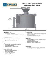
VERTICAL SHAFT IMPACT CRUSHERCrushin gWheel-MountedStationary PlantBare Unit73
Crushin gVERTICAL SHAFT IMPACT CRUSHEROPERATIONThese Vertical Shaft Impact Crushers are best applied intertiary and quaternary applications and various secondaryapplications. Rock fed to the crusher’s acceleratormechanism (table or rotor) is flung outwards by centrifugalforce against the stationary anvils or hybrid rock shelffor free-body impacting. The proper chamber configurationis application dependent.Major crushing advantages include: Precisegradation control; and production of chips andasphalt aggregates fines; compliance with cubicaland fracture count specifications, for today’s tightspecification requirements such as Superpave.74VSI Animationhttp://youtu.be/-Xn0gnB0y1w
VERTICAL SHAFT IMPACT CRUSHER—Specifications and Production CharacteristicsMinimum Standard ApproximateRecommended Capacity Impeller Recommended Explosion WeightMaximum Closed Feed Tube Effective Crushing Table Speed Electric Table/Anvil Chamber EV-Models (ElectricFeed Size (1) Circuit Diameter Range (2) Range Horsepower Clearance Volume WK 2 Shown)Model Inch MM Mesh Inch TPH MTPH RPM H.P. Inch MM Cubic Inch Lbs-Ft Lbs Kgs1500 (H) 2 50 #16 8 1 ⁄2 75-125 67-112 720-2000 75-150 10.4 260 4,635 1,100 13,200 6,0001500 (A) 2 50 #4 8 1 ⁄2 75-150 67-135 720-2000 150 — — 4,635 1,100 13,700 6,0002500 (H) 3 75 #16 11 3 ⁄8 150-250 135-223 700-1400 250 8.8 220 10,120 2,400 18,000 8,1822500 (A) 2 50 #4 11 3 ⁄8 150-300 135-267 700-1400 300 — — 10,120 2,400 19,000 8,18282 3 75 #16 14.0 250-400 227-356 800-1200 400-500 8.7 218 10,940 3,200 24,000 11,0004500 (H) 3 75 4M 16.0 300-450 267-401 800-1200 400-500 10.25 (256) 17,360 3,830 29,600 13,3204500 (H) 5 1253 ⁄8” 16.0 300-450 267-401 800-1200 400-500 11.75 294 17,360 3,830 29,600 13,3204500 (A) 2 1 ⁄2 63 #4 16.0 300-500 267-445 800-1200 400-500 — — 17,360 3,500 29,100 13,3203 ⁄8” 18.0 300-500 267-445 800-1080 400-600 14.75 369 26,020 5,600 32,100 14,595120 6 150NOTE: (H) in the model number denotes hardparts configuration also referred to as “standard configuration.”(A) in the model number denotes autogenous configuration. The specification and production rates shown apply to semi- and fully-autogenous.(1) Max feed size restriction can vary with regards to material density, crushability, elongation, and impeller table speed or configuration.(2) Feed size and throughput tonnage based on material weighing 100 lbs. per cubic foot.75Crushin g
Crushin gSecondaryAVERAGE MATERIALS CRUSHER OUTPUT,(2) USING 3-SHOE/4-SHOE IMPELLER80% of Max. 50% of Max.Max. Speed Speed Output Speed OutputSieve Size Sieve Size Feed Scalpedinches mm at 1 1 ⁄2” (1) % Passing6” 152mm5” 125mm 100%4” 100mm 100% 993” 75mm 100% 99 972” 50mm 96 91 861 1 ⁄2” 37.5mm 9081 701 1 ⁄4” 31.5mm 86 77 631” 25.0mm 78 68 527 ⁄8” 22.4mm 74 64 483 ⁄4” 19.0mm 68 56 405 ⁄8” 16.0mm 62 51 361 ⁄2” 12.5mm 53 42 303 ⁄8” 9.5mm 44 34 241 ⁄4” 6.3mm 35 27 19#4M 4.75mm 29 24 16#8M 2.36mm 17 15 11#16M 1.18mm 14 13 8#30M 600um 10 9 6#50M 300um 7 6 4#100M 150uM 5 4 3#200M 75uM 3 2 2Model 4500 Model 120Max Feed Size Range “Cubed” 4-5” (100-125 mm) 5-6” (125-150 mm)Crusher Throughput 300-450 TPH 300-500 TPHSECONDARY CRUSHING AVERAGE MATERIALS(BASALT, HARD LIMESTONE, GRAVEL/DOLOMITE) W/STANDARD CONFIGURATIONNOTE:(1) Feeds shown are typical feed gradations when following a primary jawset at 3” to 4” or a primary impactor set at 2” to 3” with product-sizedmaterial removed.(2) Crusher outputs show average values based on field experience, andare taken before screening product-sized material out. The figures areprovided for estimating required screen areas and tertiary crushingequipment when used with the expected tonnage of crusher throughput.Values will differ with each specific crushing application, so thesefigures are not guarantees. Factors that can affect output gradationinclude: Feed gradation, feed tonnage, feed friability, impeller tableconfiguration, impeller speed, moisture content, closed circuit screencloth opening, available screen area and horsepower.76
Typical Limestone inStandard ConfigurationPRODUCING A COARSE GRADED MATERIAL,EMPHASIS ON CHIPS, POPCORN ANDDIMENSIONAL PRODUCTSModels 1500H, 2500H, 82H3” Feed 2” Feed 1” FeedTertiarySieve Size Sieve Size Typical Typical Typicalinches mm Feed Output Feed Output Feed Output3” 75mm 100%2” 50mm 98 100%1 1 ⁄2” 37.5mm 94 981” 25mm 83 90 100%3 ⁄4” 19mm 69 78 951 ⁄2” 12.5mm 52 60 803 ⁄8” 9.5mm 40 46 621 ⁄4” 6.3mm 28 33 40#4M 4.75mm 20 24 30#8M 2mm 14 15 15#16M 1.18mm 9 10 10#30M 600uM 6 7 7#50M 300uM 4 5 5#100M 150uM 3 4 4#200M 75uM 2 3 3Maximum CrusherFeed Size: Throughput“Cubed” CapacityModel 1500H 2” (50mm) 75-125 TPHModel 2500H 3” (75mm) 150-250 TPHModel 82H 3” (75mm) 250-400 TPHTypical coarse gradations require 50-80% maximum speed, 3 or 4 shoetable. Typically dense gradations require 70-100% maximum speed,4 or 5 shoe table.Crushin g77
Crushin gTypical Limestone inStandard ConfigurationModels 1500H, 2500H, 82H3” Feed 2” Feed 1” FeedTertiarySieve Size Sieve Size Typical Typical Typicalinches mm Feed Output Feed Output Feed Output3” 75mm 100%2” 50mm 981 1 ⁄2” 37.5mm 95 100%1” 25mm 87 94 100%3 ⁄4” 19mm 79 85 991 ⁄2” 12.5mm 68 73 903 ⁄8” 9.5mm 57 62 78PRODUCING A DENSE GRADED MATERIAL,EMPHASIS ON FINES FOR BASE, ASPHALTMATERIAL, SAND SUPPLEMENT, ETC.1 ⁄4” 6.3mm 46 49 63#4M 4.75mm 37 40 52#8M 2mm 26 27 33#16M 1.18mm 17 18 21#30M 600uM 11 12 15#50M 300uM 7 8 10#100M 150uM 5 6 6#200M 75uM 4 4 4Feeds: Typical feeds shown have been screened to take out product-sizedmaterial, and are initial feed plus recirculating load.Outputs: These outputs show average values based on field experiencecrushing tough material, and indicate crusher output beforescreening product-sized material out. Gradation change is due toincreased impeller speed from 50% to 100% of maximum and adifference in impeller table configuration. Values will differ for eachspecific crushing application. Factors that can affect output gradationinclude: Feed gradation, feed tonnage, feed friability, impellertable configuration, impeller speed, moisture content, closed circuitscreen cloth opening, available screen area and horsepower.78
Typical Limestone inStandard Configuration*Models 1500H, 2500H, 82HApprox. Crusher OutputQuaternaryHigh RangeLow High ScreenedFeed Range Range Average at #4M*Sieve Size Sieve Sizeinches mm % Passing1” 25mm 100% 100% 100%3 ⁄4” 19mm 95 99 971 ⁄2” 12.5mm 80 90 853 ⁄8” 9.5mm 62 78 701” FEED SIZE APPLICATIONSModels 1500H, 2500H, 82HCrushing 1” top feed size for chips, popcorn, fracture count or amanufactured sweetener.Low RangeResulting from:• Tough feed material• Impeller speeds 50-80% of max.• Crusher choke-fed• 3 or 4 shoe tableHigh RangeResulting from:• Moderately tough to moderately friable feed material• Impeller speeds 80-100% of max• Crusher fed 85% of choke-feed rate, or less• Five shoe table1 ⁄4” 6.3mm 40 63 52#4 4.75mm 30 52 41 100%#8 2.36mm 15 33 24 75#16 1.18mm 10 21 15 48#30 600uM 6 15 11 34#50 300uM 5 10 7 22#100 150uM 4 6 5 13#200 75uM 3 4 3 9Shows high range with the effect of normal field screening inefficiencies.A proportional return of the coarse screen through fractions andhydraulic classification to remove a portion of the #100 mesh minus isusually required to meet ASTM C-33 specifications regarding a #4Mminus gradation.Crushin g79
Crushin gTypical Sand and Gravel inAutogenous and Semi-AutogenousConfigurationModels 1500A, 2500A, 4500ASemi-AutogenousFullyAutogenousAutogenousSieve Size Sieve Size 1 1 ⁄2” 100% 100%inches mm Feed Speed Speed2” 50mm1 1 ⁄2” 37.5mm 100%1 1 ⁄4” 31mm 99 100%1” 25mm 95 963 ⁄4” 19mm 90 90Maximum CrusherFeed Size: Throughput“Cubed” Capacity1 ⁄2” 12.5mm 70 763 ⁄8” 9.5mm 56 581 ⁄4” 6.3mm 38 45#4M 4.75mm 31 37#8M 2mm 22 25#16M 1.18mm 15 17#30M 600uM 11 13#50M 300uM 8 8#100M 150uM 6 5#200M 75uM 4 3Model 1500A 2” 75-150 TPHModel 2500A 2” 150-300 TPHModel 4500A 21 ⁄2” 300-500 TPHBased upon material weighing 2,700 lbs. per cubic yard (1600 kg/m 3 ). Capacities may vary as much as ±25% dependent upon methodsof loading, characteristics and gradation of material, conditionof equipment and other factors.80
VERTICAL SHAFT IMPACT CRUSHERCRUSHING CHAMBER TERMINOLOGYFULLY AUTOGENOUSROTOR & HYBRIDROCK SHELFRock-on-rock crushing;rotor flings rock againstbed of rock on outerhybrid rock shelf, andexposed portion of anvilslining the hybrid rock shelffor free-body impacting.Variable reduction ratiosof 10:1 to 3:1.Crushin gROTOR & ANVILCrushing chamber hasautogenous rotor andstandard stationary anvilsfor specialized crushingand materials problems;1 1 ⁄2-2” feed sizes and variablereduction ratios of10:1 to 3:1.SEMI-AUTOGENOUSSTANDARD CONFIGURATIONSHOE & ANVILImpeller shoes in chamberfling rock at trueright angles to stationaryanvils; rock gradationscontrolled by impellertable speed. Variablereduction ratios of 10:1to 3:1.81
FAST TRAX ® SCREEN PLANTSTracks<strong>KPI</strong>-<strong>JCI</strong> and Astec Mobile Screens track-mounted screens areengineered to provide higher production capacities and moreefficient sizing compared to conventional screens. Featuringtriple shaft, oval motion screens, these plants offer better bearinglife, more aggressive screening action for reduced plugging andblinding, and a consistent material travel speed that does notaccelerate through gravity for a higher probability of separation.As such, these highly efficient plants are perfect for both portableand stationary producers who need quick, effortless on-sitemovement and reduced down time.ModelScreen Size(ft / cm)FT3620 6 x 20 /183 x 609FT6203OC 6 x 20 /183 x 609FT6203CC 6 x 20 /183 x 609FT710 KDS 7 x 10 / 2134x 3048DecksProduction(tph / mtph)Weight*(lbs / kg)3 700 / 635 81000 /367413 800 / 726 83000 /376483 800 / 726 86000 /390092 200 / 181 35000 /15876*These weights should not be used to determine shipping costs. For exactweights, please consult factory personnel or your local <strong>KPI</strong>-<strong>JCI</strong> and AstecMobile Screens dealer.82
FAST TRAX ®HiGH FREQUENCY SCREEN PLANTSTracksAstec Mobile Screens high frequency screens are engineeredto provide higher production capacities and more efficient sizingcompared to conventional screens. High frequency screensfeature aggressive vibration applied directly to the screen thatallows for the highest capacity in the market for removal of finematerial, as well as chip sizing, dry manufactured sand and more.ModelScreen Size(ft / cm)FT2618V 6 x 18 /183 X 547FT2618VM 6 x 18 /183 x 547Production(tph / mtphWeight*(lbs / kg)350 / 318 62000 / 28123350 / 318 60000 / 27216*These weights should not be used to determine shipping costs. For exactweights, please consult factory personnel or your local <strong>KPI</strong>-<strong>JCI</strong> and AstecMobile Screens dealer.83
FAST TRAX ® JAW PLANTSTracks<strong>KPI</strong>-<strong>JCI</strong> Fast Trax jaw plants are built for maximum jaw crushingmobility. Featuring Vanguard Plus Series Jaw Crushers, theseplants are equally effective in aggregate or recycling applications.Both plants allow stationary and portable producers to benefit fromthe on-site mobility these plants deliver.ModelCrusher(in / mm)FT2650 26 x 50 /660 x 1270FT3055 30 x 55 /762 x 1397Feeder(in x ft / mm)50 x 15 /1270 x 457250 x 15 /1270 x 4572Grizzly (ft/ cm)5 / 152(step deck)5 / 152ModelProduction(tph / mtph)Max Feed(in / mm)Weight *(lbs / kg)FT2650 400 / 363 21 / 533 96000 /43545FT3055 700 / 635 24 / 610 124000 /56245*These weights should not be used to determine shipping costs. For exactweights, please consult factory personnel or your local <strong>KPI</strong>-<strong>JCI</strong> and AstecMobile Screens dealer.84
FAST TRAX ® KODIAK PLUS CONE PLANTSTracksFast Trax cone plants are engineered for maximum cone crushingproductivity. Each plant features a Kodiak Plus cone crusher thatdelivers efficient material sizing, making them perfect for bothmobile and stationary producers who need quick, effortless on-sitemovement.Model Crusher Belt Feeder(in x ft / mm)FT300DF+KodiakPlus 30042 x 43 / 1067x 7010Capacity(tph / mtph)460 / 417ModelMax Feed Size(in / mm)Weight*FT300DF+ 11 / 2794 96000 /43548*These weights should not be used to determine shipping costs. For exactweights, please consult factory personnel or your local <strong>KPI</strong>-<strong>JCI</strong> and AstecMobile Screens dealer.85
FAST TRAX ® IMPACTOR PLANTSTracks<strong>KPI</strong>-<strong>JCI</strong> Track Mounted impactor plants are engineered for maximumimpact crushing versatility. Featuring Andreas Series Impact Crushers,these plants come equipped with our standard Overload ProtectionSystem (OPS). Delivering dramatically superior performance with aneasily adjustable interface, aggregate producers and recyclers alikewill benefit from the availability of open or closed circuit configurations,complete with a screen and recirculating conveyor.ModelCrusher(in / mm)Feeder(in x ft /mm)Grizzly(ft / cm)Production(tph/ mtph)Weight*(lbs / kg)FT4240CC 42 x 40/ 1067 x101640 x 14/ 1016 x42674 / 122(straight)325 / 295 94000 /42638FT4240OC 42 x 40/ 1067 x101640 x 14/ 1016 x42674 / 122(straight)325 / 295 81000 /36741FT4250CC 42 x 50/ 1067 x127050 x 15/ 1270 x45725 / 152(stepdeck)400 / 363 112500 /51029FT4250OC 42 x 50/ 1067 x127050 x 15/ 1270 x45725 / 152(stepdeck)400 / 363 99000 /44906FT5260 52 x 60/ 1321 x152450 x 15/1270 x45725 /152(stepdeck)750 / 680 112500 /51029*These weights should not be used to determine shipping costs. For exactweights, please consult factory personnel or your local <strong>KPI</strong>-<strong>JCI</strong> and AstecMobile Screens dealer.86
GLOBAL TRACK SCREENING PLANTSTracksGT mobile screening plants feature double- or triple-deck screensfor processing sand and gravel, topsoil, slag, crushed stone andrecycled materials. They provide easy-to-reach engine controls andgrease points for routine service, simple-to-use hydraulic levelinggears, hydraulic plant controls and screen angle adjustment. Tetheredtrack remote control is standard with an optional wireless remote trackcontrol available.ModelHopperCapacity(yd / m)Screen Size(ft / m)GT145 10.5 / 8.03 5 x 14 /1.52 x 4.27GT205 10.5 / 8.03 5 x 20 /1.52 x 6.10Power(hp / kw)129 / 96129 / 96ModelCapacity(tph / mtph)GT145 650 / 540 24 / 610Overs Conveyor(in / mm)GT205 650 / 540 30 / 76287
GLOBAL TRACK DIRECT FEED PLANTSTracksGT direct feed plants provide a rugged, mobile screening tool in ahighly portable configuration. They were designed to provide aversatile screening plant that would handle high volumes of material inboth scalping and sizing applications. The large loading hopper with aHD variable speed apron pan feeder can withstand heavy loads whilemetering feed material to the screen to optimize screening productionand efficiency.ModelBeltFeeder(in / mm)Screen Size(ft / m)GT165 54 / 1372 5 x 16 / 1.52x 4.488Power(hp / kw)Capacity(tph /mtph)OversConveyor(in / mm)129 / 96 650 / 540 54 / 137288
GLOBAL TRACK JAW PLANTSTracksThe GT125 is your choice for maximum jaw crushing mobility.Featuring a Vanguard Series Jaw Crusher, the GT125 provides alarge feed opening for up to 400 TPH. Equally effective in aggregateor recycle applications, this plant allows stationary and portableproducers to benefit from the on-site mobility. Cross-belt magnet,under grizzly side delivery and dust-suppression systems are optionsavailable to customize the plant to exact specifications.ModelCrusher(in / mm)GT125 26 x 40 /660 x 1012Feeder (in xft / mm)40 x 14 /1016 x 4267Grizzly(ft / cm)4 / 122(straight)ModelCapacity(tph / mtph)Max FeedSize (in / mm)Weight *(lbs / kg)GT125 325 / 295 21 / 533 83000 /37648*These weights should not be used to determine shipping costs. For exactweights, please consult factory personnel or your local <strong>KPI</strong>-<strong>JCI</strong> and AstecMobile Screens dealer.89
GLOBAL TRACK CONE PLANTSTracksGlobal Track cone plants feature a quarry-duty, state of the art conecrusher design in a highly mobile package. At up to 385 TPH ofefficient crushing capacity, they provide the lowest operating cost intheir class. They can be deployed quickly for maximum flexibility toeconomically process small volume jobs and are designed to be assimple to operate and maintain as possible.Model Crusher Belt Feeder(in x ft / mm)GT200DFGT200CCKodiak200 PlusKodiak200 Plus42 x 43 /1067 x 701042 x 43 /1067 x 7010Capacity(tph / mtph)385 / 347385 / 347ModelMax Feed Size(in / mm)Weight*(lbs / kg)GT200DF 9 / 228.6 80000 /32290GT200CC 9 / 228.6 103000 /46720*These weights should not be used to determine shipping costs. For exactweights, please consult factory personnel or your local <strong>KPI</strong>-<strong>JCI</strong> and AstecMobile Screens dealer.90
GLOBAL TRACK CONVEYORTracksThe GT3660 is a self-contained, track-mounted, mobile conveyor thatcan be used as a transfer or stacking conveyor with portable or trackcrushing and screening equipment.Capable of carrying loads of up to 750 tons per hour with adjustablespeed and discharge height, the GT3660 is a perfect tool when quickset-up, mobility and flexibility are required.ModelBelt Width(in / mm)Belt Length(ft / m)Diesel Power(hp / kw)GT3660 36 / 900 60 / 18.25 60 / 45ModelCapacity(tph / mtph)Discharge Height(ft/ m)GT3660 750 / 675 24 / 7.31591
Washin g/Classifyin gWASHINGINTRODUCTIONClean aggregates are important to the constructionindustry. Yet producers of aggregates frequently arehard-pressed to meet all requirements for “cleanliness.”Materials engineers constantly strive to improve concreteand bituminous mixes and road bases. While hydraulicmethods are the most satisfactory for cleaning aggregatesto achieve the desired result, they are not always perfect.It is still necessary to accept materials on the basis ofsome allowable percent of deleterious matter.In the broadest terms, construction aggregates arewashed to make them meet specifications. Specifically,however, there is more to the function of water in processingaggregates than mere washing. Among thesefunctions are:1. Removal of clay and silt2. Removal of shale, coal, soft stone, roots, twigsand other trash3. Sizing4. Classifying or separating5. DewateringBecause no washing method can be relied upon to beperfect, and because some materials may require toomuch time, equipment and water to make them conformto specifications, it is not always economically practicalto use such materials. It is important, therefore, to testthe source thoroughly beforehand to ensure the desiredfinished aggregates can be produced at reasonable cost.The project materials engineer can be of immeasurablehelp in determining the economic suitability of thematerial, and generally must approve the source beforeproduction begins, anyway. Further, many manufacturersof washing equipment will examine and test samples todetermine whether their equipment can do the job satisfactorily.No reputable equipment manufacturer wants torecommend his equipment where he has a reasonabledoubt about its satisfactory performance on the job.92
The ideal gradation is seldom, if ever, met in naturallyoccurring deposits. Yet the quality and control of thesegradations is absolutely essential to the workability anddurability of the end use. Gradation, however, is a characteristicwhich can be changed or improved with simpleprocesses and is the usual objective of aggregate preparationplants.Crushing, screening and blending are methods used toaffect the gradations of aggregates. However, even followingthese processes, the material may still requirewashing to meet specification as to cleanliness. Also,screening is impractical smaller than No. 8 mesh andhence, hydraulic separation, or classifying, becomes animportant operation.Washing and classifying of aggregates can be consideredin two parts, depending on the size range of material.Coarse material - generally above 3/8” (sometimes splitat 1/4” or 4 mesh). In the washing process, it usually isdesired to remove foreign, objectionable material, includingthe finer particles.Fine aggregates - from 3/8” down. In this case, it generallyis necessary to remove dirt and silt while retainingsand down to 100 mesh, or even 200 mesh.Washin g/Classifyin g93
Washin g/Classifyin gThis term is used to denote the distribution of sizes of theparticles of aggregates. It is represented by a series of percentagesby weight of particles passing one size of sievebut retained by a smaller size. The distribution is determinedby a mechanical analysis performed by shaking theaggregate through a series of nested sieves or screens,in descending order of size of openings. Round openingsare used for larger screens, square ones for the smallersieves. Prescribed methods and prescribed openings ofthe screens and sieves have been established by theASTM (American Society for Testing Materials). The normalseries of screens and sieves is: 1 1 ⁄2”, 3 ⁄4”, 3 ⁄8”, Numbers4, 8, 16, 30, 50, 100, 200 mesh.94GRADATION OF AGGREGATESSIEVES FOR TESTING PURPOSESScreen or Sieve Nominal Opening EquivalentsDesignation mm inches microns4” 101.63” 76.22” 50.81 1 ⁄2” 38.11” 25.43⁄4” 19.11⁄2” 12.73⁄8” 9.521⁄4” 6.35No.4 4.76 0.187 47606 3.36 0.132 33608 2.38 0.0937 238012 1.68 0.0661 168016 1.19 0.0469 119020 0.84 0.0331 84030 0.59 0.0232 59040 0.42 0.0165 42050 0.297 0.0117 29770 0.210 0.0083 210100 0.149 0.0059 149140 0.105 0.0041 105150 0.100 0.0039 100200 0.074 0.0029 74270 0.053 0.0021 53400 0.037 0.0015 37
GRADING REQUIREMENTS FOR COARSE AGGREGATESAmounts Finer than Each Laboratory Sieve (Square-Openings), Weight Percent3 1 3⁄4 in. ⁄2 in. ⁄8 in. No. 4 No. 8 No. 16Normal Size(Sieves with 4 in. Size 3 1 ⁄2 in. 3 in. 2 1 ⁄2 in 2 in. 1 1 ⁄2 in. 1 in. Number Square Openings) (100 mm) (90 mm) (75 mm) (63 mm) (50 mm) (37.5 mm) (25.0 mm) (19.0 mm) (12.5 mm) (9.5 mm) (4.75 mm) (2.36 mm) (1.18 mm)1233574467556576677831⁄2 to 11⁄2 in.(90 to 37.5 mm)2 1 ⁄2 to 1 1 ⁄2 in.(63 to 37.5 mm)2 to 1 in.(50 to 25.0 mm)2 in to No. 4(50 to 4.75 mm)1 1 ⁄2 to 3 ⁄4 in.(37.5 to 19.0 mm)1 1 ⁄2 in to No. 4(37.5 to 4.75 mm)1 to 1 ⁄2 in.(25.0 to 12.5 mm)1 to 3 ⁄8 in.(25.0 to 9.5 mm)1 in. to No. 4(25.0 to 4.75 mm)3⁄4 to 3 ⁄8 in.(19.0 to 9.5 mm)3⁄4 in. to No. 4100 90 - 100 25 - 60 0 - 15 0 - 5100 90 - 100 35 - 70 0 - 15 0 - 5100 90 - 100 35 - 70 0 - 15 0 - 5100 95 - 100 35 - 70 10 - 30 0 - 5100 90 - 100 20 - 55 0 - 15 0 - 5100 95 - 100 35 - 70 10 - 30 0 - 5100 90 - 100 20 - 55 0 - 10 0 - 5100 90 - 100 40 - 85 10 - 40 0 - 15 0 - 5100 95 - 100 25 - 60 0 - 10 0 - 5100 90 - 100 20 - 55 0 - 15 0 - 5(19.0 to 4.75 mm)1100 90 - 100 20 - 55 0 - 10 0 - 5⁄2 in. to No. 4100 90 - 100 40 - 70 0 - 15 0 - 5(12.5 to 4.75 mm)3⁄8 in. to No. 8(9.5 to 2.36 mm)100 85 - 100 10 - 30 0 - 10 0 - 5Washin g/Classifyin g95
SAND SPECIFICATIONSCommon sand specifications are ASTM C-33 for concretesand and ASTM C-144 for mason sand. These specificationsare often written numerically and also showngraphically.Washin g/Classifyin gASTM C-33LimitsCenter SpecSieve % Passing % Passing3 ⁄8” 100 100No. 4 95-100 97.58 80-100 9016 50-85 67.530 25-60 42.550 5-30 17.5100 0-10 5200 0-3 1.5ASTM C-144LimitsCenter SpecSieve % Passing % Passing3 ⁄8” 100 100No. 4 100 1008 95-100 97.516 70-100 8530 40-75 57.550 10-35 22.5100 2-15 8.5200 0-10 596
PERCENT PASSING010203040100908070605040302050ASTM C-3360701008090100PERCENT PASSING3/8 1/4 4 6 8 10 12 16 20 30 40 50 70 80 100 140 200U.S.MM 9.5 6.3 4.75 3.35 2.36 2.0 1.7 1.18 600 425 300 212 180 150 106 750.375 0.250 0.187 0.132 .0937 .078.066 .0469 .0234 .0165 .0117 .0083 .0070 .0059 .0041 .0029DECIMAL .0331 97Washin g/Classifyin g
PERCENT PASSINGASTM C-1444 6 8 10 12 16 20 30 40 50 70 80 100 140 200U.S.01020304010090807060504030205060701008090100Washin g/Classifyin g984.75 3.35 2.36 2.0 1.7 1.18 850 µ M 600 425 300 212 180 150 106 75MMPERCENT PASSINGDECIMAL 0.187 0.132 .0937 .078 .066 .0469 .0331 .0234 .0165 .0117 .0083 .0070 .0059 .0041 .0029
FM AND SEThe factor called Fineness Modulus (FM), which is commonlyused, serves as a quick check that a given samplemeets specifications without checking each sieve sizeof material against the standards set for a particular job.FM is determined by adding the cumulative retained percentagesof sieve sizes #4, 8, 16, 30, 50 and 100 anddividing the sum by 100.Sieve % Passing % Retained#4 97 3#8 81 19#16 59 41#30 36 64#50 15 85#100 4 96308 / 100 = 3.08 (FM)Different agencies will require different limits on the FM.Normally, the FM must be between 2.3 and 3.1 for ASTMC-33 concrete sand with only 0.1 variation for all thematerial used throughout a certain project.The Sand Equivalent Test (SE) is more complex thanthe FM test. The “equivalent” refers to the equivalentquantities of fine versus coarse particles in a givensand sample. The test is performed by selecting agiven quantity of a sand sample and mixing it in aspecial solution. The chemicals in the solution containexcellent wetting agents. These wetting agents willrapidly dissolve any deposits of semi-insoluble claysor plastic clays, which are clinging to the individualsand particles. After a specified period of agitation,either by hand or by machine, the sample is allowed tostand in a graduated tube for a specified time period.A weighted plunger is slowly lowered into the settledsand-solution mixture, and the depth to which theweight descends is noted from the graduations on thetube. A formula is supplied with the testing apparatus,and from that formula the “SE” is determined.Washin g/Classifyin g99
In general, the finer the sand, the deeper the weight willpenetrate. The wetting agents that dissolve the clay makea seemingly coarse material much finer because the claysare now a separate, very fine product. This extra finematerial acts as a lubricant and the weight will descenddeeper in the sample. Because of this, it is possible thata sample with an acceptable FM is rejected for failure topass the SE test.Washin g/Classifyin gCOARSE MATERIAL WASHINGIn order to produce aggregate at the most economicalcost, it is important to remove, as soon as possible,from the flow of material, any size fraction that can beconsidered ready for use. The basic process consists ofcrushing oversize material, scrubbing or washing coatingsor entrapped materials, sorting and dewatering.Beneficiation of some coarse aggregate fractions maybe necessary. When scrubbing or washing of coarsematerial is required, it is generally a consideration of thematerial size, the type of dirt, clay or foreign material tobe scrubbed and the tons-per-hour rate needed that willdetermine the coarse material washing equipment to use.100
LOG WASHERSPurpose: In the aggregate business, the log washer isknown best for its ability to remove tough, plastic solubleclays from natural and crushed gravel, crushed stoneand ore feeds. The log washer will also remove coatingsfrom individual particles, break up agglomerations, andreduce some soft, unsound fractions by a form of differentialgrinding.Design: The log washer consists of a trough or tank ofall welded construction set at an incline (typically 6-10°)to decrease the transport effect of the paddles and toincrease the mass weight against the paddles. Each“log” or shaft (two per unit) is fitted with four rows of paddleswhich are staggered and timed to allow the paddlesof each shaft to overlap and mesh with the paddles ofthe other shaft. The paddles are pitched to convey thematerial up the incline of the trough to the discharge end.Washin g/Classifyin g101
Washin g/Classifyin g<strong>KPI</strong>-<strong>JCI</strong> and Astec Mobile Screens’ log washer designimproves on the traditional design in that the paddlesare set in a spiral pattern around the shaft instead of ina straight line as in competitive units. This design featureprovides many benefits, including: 1) Reduces intermittentshock loading of the log, 2) Keeps a portion of themass in motion at all times, thus reducing power peaksand valleys as well as overall power requirements,3) Reduces wear and 4) Provides more effective scrubbing.Other important features of the log washer includetwo large tank drain/clean-out ports, rising current inlet,overflow ports on each side of the unit, cast ni-hard paddleswith corrugated faces, readily-available externallymounted lower end bearings and a custom-designed andmanufactured single-input dual-output gear reducer.Application: The majority of the scrubbing actionperformed by the log washer is accomplished by theabrading action of one stone particle on another, not bythe action of the paddles on the material. Due to thisand other feed material characteristics such as clay solubility,the capacity of a log washer is given in a fairlywide range. Normal practice is to follow the log washerwith a screening device on which spray bars are used toremove fines and clay coatings on the stone.LOG WASHERSWater Maximum Approx. Approx.Capacity Motor Req’d. Feed Size Dead Load Live LoadModel (TPH) (HP) (GPM) (in.) (lbs.) (lbs.)8024-18 25-80 40 25-250 3” 12,500 15,0008036-30 85-200 100 50-500 4” 34,000 45,0008048-30 125-300 150 100-800 5” 47,500 70,0008048-35 125-400 200 100-800 5” 53,000 83,000102
COARSE MATERIAL WASHERSPurpose: The coarse material washer is used toremove a limited amount of deleterious material froma coarse aggregate. This deleterious material includesshale, wood, coal, dirt, trash and some very solubleclay. A coarse material washer is often used as finalwash for coarse material (typically -2 1 ⁄2” x + 3 ⁄8”) followinga wet screen. Both single and double spiral unitsare available depending on the capacity required.Design: The coarse material washer consists of along vertical sided trough or tank of all welded constructionset at a 15° incline. The shaft(s) or spiral(s) ofa coarse material washer begin with one double pitchspiral flight with replaceable ni-hard outer wear shoesand AR steel inner wear shoes. Following this singleflight is a variable number of bolt-on paddle assemblies.Standard units include four sets of paddle armswith ni-hard tips. Two sets of arms replace one fullspiral. The balance of the spiral(s) consists of doublepitch spiral flights with replaceable ni-hard outer wearshoes and AR steel inner wear shoes.Washin g/Classifyin g103
Washin g/Classifyin gOther important features of the coarse material washerinclude a rising current manifold, adjustable full widthoverflow weirs, readily-available, externally-mountedlower end bearing(s) and upper end bearing(s) and shaftmounted gear reducer with v-belt drive assembly (onedrive assembly per spiral).Application: As previously noted, the number of paddleassemblies can be varied. The number of paddleassemblies installed on a particular unit is dependenton the amount of water turbulence and scrubbingaction required to suitably clean the feed material. Asthe number of paddles is increased, the operationalcharacteristics of the unit change, including increasedscrubbing action, increased retention time, reducedcapacity and increased power requirements.ModelCOARSE MATERIAL WASHERSCapacity(TPH)Motor(HP)SINGLE SPIRAL CONFIGURATIONS.6024-15S6036-19S6048-23S60-75150-175200-250152540TWIN SPIRAL CONFIGURATIONS.6036-19T6048-23T300-350400-5002540WaterRequired(GPM)300-400400-600500-700700-900800-1000MaxFeedSize(in.)2½”2½”3”2½”3”Approx.DeadLoad(LBS)6,20010,40015,60017,00028,500NOTE: Two motors required on twin units. 24” diameter unit offered only insingle spiral configuration.Approx.LiveLoad(LBS)9,00019,00038,50037,00078,000104
BLADEMILLSPurpose: Similar in design to the Series 6000 CoarseMaterial Washer, the blademill is used to pre-conditionaggregates for more efficient wet screening. Blademillsare generally used prior to a screening and washingapplication to break up small amounts of soluble mudand clay. Typical feed to a blademill is 2 1 ⁄2” x 0”. Unitsare available in both single- and double-spiral designs,depending on the capacity required.Design: The blademill consists of a long vertical sidedtrough or tank of all welded construction set at a variableincline (typically 0-4°), depending on the degree of scrubbingor pre-conditioning required. The shaft(s) or spiral(s)of a blademill begin with one double pitch spiral flight withreplaceable ni-hard outer wear shoes and AR steel innerwear shoes. Following this single flight is a combination ofbolt-on paddle and flight assemblies, which can be varied,depending on the amount of scrubbing required. The flightassemblies include replaceable ni-hard outer wear shoesand AR steel inner wear shoes. The paddle assembliesare fitted with replaceable cast ni-hard paddle tips. Otherimportant features of the blademill include readily-available,externally-mounted lower end bearing(s) and upperend bearing(s) and shaft mounted gear reducer with v-beltdrive assembly (one drive assembly per spiral).Washin g/Classifyin g105
Washin g/Classifyin gApplication: The number of paddle and flight assemblies,as well as the angle of operation, can be varied dependentupon the amount of scrubbing or pre-conditioningrequired. As the number of paddles or angle of operationis increased, the operational characteristics of the unitchange, including increased scrubbing action, increasedretention time, reduced capacity and increased powerrequirements.Capacities/Specifications: Blademill capacity is indirectlya function of retention time. Each application willindicate a required period of time for effective washing,which actually determines the capacity of the unit. As arule of thumb, a blademill can be expected to processin the range of a coarse material washer with respect toraking capacity in TPH and requires approximately 1 ⁄4 to1⁄3 of the water required in a coarse material washer. Ifsufficient information is not available with regards to claycontent and solubility, the lower end of the coarse materialwasher range should be used. Blademills are offeredin single or twin screw configurations of the same size ascoarse material washers.ModelCapacity(TPH)BLADEMILLSMotor(HP)SINGLE SPIRAL CONFIGURATIONS.6524-15S6536-19S6548-23S60-75150-175200-250152540TWIN SPIRAL CONFIGURATIONS.6536-19T6548-23T300-350400-5002540WaterRequired(GPM)75-150100-200125-250175-350200-400MaxFeedSize(in.)2½”2½”3”2½”3”Approx.DeadLoad(LBS)6,9009,80017,70017,20031,100NOTE: Two motors required on twin units. 24” diameter unit offered onlyin single spiral configuration.Approx.LiveLoad(LBS)7,50015,80030,70028,30057,600106
FINE MATERIAL WASHINGAND CLASSIFYINGINTRODUCTIONAside from washing sand to remove dirt and silt, hydraulicmethods are employed to size the material and toclassify or separate it into the proper particle designation.After these steps, it is usual procedure to dewaterthe product.Washing aggregates to clean them is not new. However,much closer attention has been given to both thecleanliness and the gradation of the fines in constructionaggregates. This has developed a new “art” in theprocessing of fine aggregates. This “art” requires moretechnical know-how and methods more precise thanthose usually associated with the mere washing of graveland rock. At the same time, it has been necessary toadvance the art in a practical way so as to produce materialat a reasonable price.Screening is the best way to separate coarse aggregatesinto size ranges. With fine materials, however, screeningon less than No. 8 mesh usually is impractical. Thisnecessitates a split between 3 ⁄8” and #4 mesh puttingeverything finer into the category of requiring hydraulicseparation for best gradation control.With hydraulic separation, a large amount of water isused. Here, separation depends on the relative buoyanciesof the grain particles and on their settling rates underspecific conditions of water flow and turbulence. In somecases, separation depends on the relative specific gravitydifference between the materials to be separated andthe hydraulic medium. In a certain sense, this applieswhen water is used to separate particle sizes of sands.Perhaps it would be more apt to say this separation ofsands is based on relative densities or that the processseparates by gravity.Washin g/Classifyin g107
Washin g/Classifyin gIn its strictest sense, however, classifying means thatseveral sizes of sand products of equal specific gravitycan be separated while rejecting slimes, silt and similardeleterious substances. But sand particles are notnecessarily always of the same specific gravity, so frequentlyboth specific gravity and particle size affect therate of settling. Consequently, you cannot always estimatethe probable gradation of the final products withoutpreliminary tests on the material. Nor can you be sure ofproduct quality without analysis and tests after processing.In any hydraulic classification of sand, the amount offines retained with the final product will be dependentupon:1. Area of settling basin2. Amount of water used3. Extent of turbulence in settling areaObviously, the area of the settling basin generally will befixed. Hence, the amount and size of fines to be rejectedwill be determined by regulating the water quantity andturbulence.108
FINE MATERIAL WASHERSPurpose: Fine material washers, also frequently calledscrew classifiers or screw dehydrators, are utilized toclean and dewater fine aggregates (typically – 3 ⁄8” or -#4mesh), fine-tune end products to meet specifications andto separate out slimes, dirt and fines (typically -#100 meshor finer). Available in both single and twin configurations,fine material washers are most often used after a sandclassifying/blending tank or after a wet screening operation.Design: The fine material washer consists of an allweldedtub set at an incline of approximately 18.5°(4:12 slope) and includes a full-length curved bottomwith integral rising current manifold designed to controlfines retention and the water velocity within the pool. Thelower end of the tub or tank is flared to provide a largeundisturbed pool, which provides accurate material classification.Long adjustable weirs around the top of thesides and end of the tub’s flared portion are designedto handle large volumes of slurry and to control the poollevel for uniform overflow. Also incorporated into thedesign of the tub is a chase water line to clear the draintrough for better dewatering and an overflow flume.Washin g/Classifyin g109
The shaft(s) or spiral(s) of the fine material washer consistof a double pitch, solid flight spiral, complete with ARsteel inner wear shoes and urethane outer wear shoes,to provide protection of the entire flight (cast ni-hard outerwear shoes are optional). Other important features of thefine material washer include readily-available, externallymountedlower end bearing(s) and upper end bearing(s),shaft mounted gear reducer with v-belt drive assembly(one drive assembly per spiral), and center feed box withinternal and external baffles to reduce the velocity of thematerial entering the fine material washer, and reducepool turbulence, enhancing fines retention.Washin g/Classifyin gApplication: Two important elements must be consideredwhen sizing a fine material washer for a particularapplication: 1) Calculation of overflow capacities and 2)Calculation of sand raking capacity. Overflow capacityis critical to ensure that the unit has sufficient capacity tohandle the water required for proper dilution of the feedmaterial, which allows for proper settling to occur and toproduce the desired split point. The requirements for waterin a fine material washer are to have approximately 5 GPMof water for every 1 STPH of total sand feed or 50 GPM ofwater for every 1STPH of silt (-#200 mesh). The larger ofthese two figures and the desired mesh split to be producedwithin the fine material washer are then used to assist insizing of the unit. This process allows for proper dilution ofthe sand so that the material will correctly settle in the tub.The raking capacity of a fine material washer is governedby the fineness of the material to be dewatered. Generallyspeaking, the finer the material to be raked, the slower thespiral speed must be, to ensure adequate dewatering andreduced pool turbulence. The following tables are providedto assist in the proper selection of a fine material washer.110PERCENT SCREW SPEED vs. PERCENT FINES(in the product)% SCREW SPEED % PASSING % PASSING % PASSING(RPM) 50 MESH 100 MESH 200 MESH100% 15 2 075% 20 5 050% 30 10 325% 50 25 8
FINE MATERIAL WASHERSRAKING & OVERFLOW CAPACITY TABLECAPACITY MINIMUM OVERFLOW CAPACITIESSINGLE/ SPIRAL SPIRAL MOTOR HP (GPM)TWIN SPEED SPEED REQ’D/ SINGLE/TWINMODEL (TPH) % (RPM) SPIRAL 100 MESH 150 MESH 200 MESH50 100% 32 7.5*5024-25 37 75% 24 5 500 225 12525 50% 16 512 25% 8 375 100% 25 10*5030-25 55 75% 19 10 550 275 15038 50% 13 7.518 25% 7 5100/200 100% 21 155036-25 75/150 75% 15 10 700/1200 325/600 175/30050/100 50% 12 7.525/50 25% 6 5175/350 100% 17 205044-32 130/260 75% 13 15 1500/2700 750/1300 400/75085/170 50% 9 1045/90 25% 5 7.5200/400 100% 16 205048-32 150/300 75% 12 15 1650/2900 825/1450 450/825100/200 50% 8 1050/100 25% 4 7.5250/500 100% 14 305054-34 185/370 75% 11 25 1800/3200 900/1600 525/900125/250 50% 7 1560/120 25% 4 10Washin g/Classifyin g325/650 100% 13 305060-35 250/500 75% 9 25 2200/3600 1000/1800 550/950165/330 50% 5 2085/170 25% 3 15400/800 100% 11 405066-35 300/600 75% 8 30 2400/4000 1100/2000 625/1000200/400 50% 5 25100/200 25% 3 15475/950 100% 11 605072-38 355/710 75% 8 50 2600/4400 1250/2200 700/1200235/475 50% 5 30120/240 25% 3 15NOTE: Two motors required on twin units.*24” & 30” dia. units offered only in single spiral configuration.111
Washin g/Classifyin gNOTE: All flows shown are in gpm. Bold italicized flows depict overflow ratesrequired for 200, 150 & 100 mesh splits respectively.FINE MATERIAL WASHER WEIR OVERFLOW RATES112AVERAGE DEPTH OVER WEIRMODEL WEIR LENGTH 1 ⁄4” 1 ⁄2” 3 ⁄4” 1” 1 1 ⁄4” 1 1 ⁄2” 1 3 ⁄4” 2” 2 1 ⁄4” 2 1 ⁄2”125 225 5005024-25S 15’3” 92 229 397 564 717 991 1205 1449 1678 1983150 275 5505030-25S 15’9” 95 236 410 583 740 1024 1244 1496 1733 2048175 325 7005036-25S 16’3” 98 244 423 601 764 1056 1284 1544 1788 2113300 600 12005036-25T 19’9” 119 296 514 731 928 1284 1560 1876 2173 2568400 750 15005044-32S 22’0” 132 330 572 814 1034 1430 1738 2090 2420 2860750 1300 27005044-32T 26’0” 156 390 676 962 1222 1690 2054 2470 2860 3380450 825 16505048-32S 22’3” 134 334 579 823 1046 1446 1758 2114 2448 2893825 1450 29005048-32T 26’9” 160 401 696 990 1257 1739 2113 2541 2943 3478525 900 18005054-34S 26’0” 156 390 676 962 1222 1690 2054 2470 2860 3380900 1600 32005054-34T 31’0” 186 465 806 1147 1457 2015 2449 2945 3410 4030550 1000 22005060-35S 26’6” 159 398 689 981 1246 1723 2094 2518 2915 3445950 1800 36005060-35T 31’6” 189 473 819 1166 1481 2048 2489 2993 3465 4095625 1100 24005066-35S 27’3” 164 409 709 1008 1281 1771 2153 2589 2998 35431000 2000 40005066-35T 32’9” 197 491 852 1212 1539 2129 2587 3111 3603 4258700 1250 26005072-38S 27’9” 167 416 722 1027 1304 1804 2192 2636 3053 36081200 2200 44005072-38T 34’3” 206 514 891 1267 1610 2226 2706 3254 3768 4453
CLASSIFICATION METHODSAPPLIED TO FINE AGGREGATESINTRODUCTIONClassification is the sizing of solid particles by means ofsettling. In classification, the settling is controlled so thatthe very fines, silts and clays will flow away with a streamof the water or liquid, while the coarse particles accumulatein a settled mass.Washing/classifying equipment is manufactured inmany different configurations depending on the naturalmaterial characteristics and the end product(s) desired.Although the general definition of aggregate classifyingcan be applied to coarse material (+ 3 ⁄8”), it is mostcommonly applied to the material passing 3 ⁄8”. Includedin the fine material classifying equipment are the sandscrews, counter-current classifiers, sand drags and rakes,hydro-cyclones, hydro-classifiers, bowl classifiers, hydroseparators,density separators, and scalping/classifyingtanks.All the above-mentioned classifiers, except the scalping/classifying tank, are generally single product machineswhich can only affect the gradation of the end producton the very fine side (the overflow separation size). Thisseparation size, due to the mechanical means employed,is never a knife-edge separation. However, the aim ofmodern classification methods is to approach a clean-cutdifferentiation. Many material specifications today call formultiple sizing of sand with provisions for blending backto obtain the gradations required. It is rare to find theexact blend occurring naturally or to economically manufacturethe blend to exact specifications. In either case,the accepted procedure is to screen out the fine materialfrom which the sand specifications will be obtained. Thismaterial is processed in a water scalping/classifying tankfor multiple separation by grain sizes or particle specificgravity.There is no mystery connected with classifying tanks.They are merely long settling basins capable of holdinglarge quantities of water. The water and sand mixWashin g/Classifyin g113
Washin g/Classifyin g(slurry) is introduced into the tank at the feed end. Theslurry, which often comes from dredging or wet screeningoperations, flows toward the overflow end, and as itdoes, solids settle to the bottom of the tank. Weight differencesbetween sand particles allow coarser materialto settle first while lighter material progressively settlesout further along the tank length.PRINCIPLES OF SETTLINGThe specific gravity of aggregates varies according tothe nature of the minerals in the rock. “Bulk” specificgravity is used in aggregate processing and indicates therelative weight of the rock or sand, including the naturalpores, voids and cavities, as compared to water (specificgravity = 1.0). In the case of fine aggregates, thespecific gravity is about 2.65. As a consequence, theweight of grains of sand will be directly proportional totheir volume. All grains of sand of a given size will thereforeweigh the same, and the weight can be measured inrelation to the opening of the sizing sieve.A second basic consideration is that of the density orspecific gravity of the slurry itself. Dilution is usuallyexpressed in percentages by weight of either the solidor of the water. Since the specific gravity of water is 1.00and that of sand is assumed to be 2.65, a simple calculationwill give the specific gravity, or density, of the slurrymixture.CALCULATION OF SLURRY OR PULPThe following method of calculating slurry or pulp isquick, accurate and requires no reference tables. It maybe used for any liquid-solid mixture.Basic equation, for a single substance or mixture:4GPM = TPH x SGFor Water: GPM Water = TPH Water x 44For Solids: GPM Solids = TPH Solids x SG Solids114
For Solids SG 2.65-2.70 (sand, gravel, quartz, limestone):GPM Solids = TPH Solids x 1.54For Slurry: GPM Slurry = TPH Slurry x SG SlurryTo solve for Specific Gravity:TPH Slurry x 4SG Slurry = GPM SlurryExample:Given: 10 TPH of Sand @ 40% Solids (by weight)Find: GPM and SG of SlurryUse this matrix to calculate your data% Weight TPH SG GPMWater 1.0Solids 40 10 2.67Slurry 100Fill in as follows:1) Convert % Weight to decimel form: 40% = 0.402) TPH Slurry = TPH solids divided by 0.40 = 253) TPH Water = TPH Slurry - TPH Solids = 154) GPM Water = TPH Water x 4 = 605) GPM Solids = TPH Solids x 1.5 = 156) GPM Slurry = GPM Water + GPM Solids = 757) SG Slurry = TPH Slurry x 4/GPM Slurry = 1.33% Weight TPH SG GPMWater 60 15 1.0 60Solids 40 10 2.67 15Slurry 100 25 1.33 75The tablulation can be solved for all unknowns if SG Solidsand two other principal quantities are given.If GPM Slurry, % Solids and SG Solids are given, solvefor 1 TPH and divide total GPM Slurry by resultant GPMSlurry to obtain TPH Solids.Rework tabulation with this figure to check the result.Percent Solids by Volume may be calculated directlyfrom GPM column.115Washin g/Classifyin g
Washin g/Classifyin gGPM column may also be extended to any other unitdesired; e.g., cubic feet per second.NOTE:1) The equation is based on U.S. Gallon and std. (short) ton of2,000 lbs.2) The difference in result by using 2.65 or 2.70 SG Solids isnegligible compared to the inaccuracy usually inherent ingiven quantities.3) For sea water, use SG 1.026. In this case, the difference isappreciable.CONVERSION FACTORSTo Obtain Multiply By Based OnTPH Cu. Yd/Hr. 1.35 Sand 100#/cu. ft., dry.Short TPH Long TPH 1.12 2240 lb. tonShort TPH Metric TPH 1.1023 Kilo = 2.2046 lb.U.S. GPM British GPM 1.201U.S. GPM Cu. Ft./Min. 7.48U.S. GPM Cu. Ft./Sec. 448.5The third consideration is that of viscosity. Viscosity canbe compared to friction in that it is a resistance to movementbetween liquid particles and between solid andliquid particles.In a continuous process, such as in the production of fineaggregates, the slurry flows into and out of the classifyingtank at a measurable rate, which determines its velocityof flow through the tank. The solids settle out, due totheir weight, at a speed that is expressed as rate of fallor settling. It is the interrelationship between these twomovements which governs the path of the falling particle.FEEDOVERFLOWDABCDEDIAGRAM OF FORCESVOGLALBLCLDLEHORIZONTAL TRAVEL OF FALLINGSAND PARTICLESPATH OF PARTICLESettling From A Surface CurrentIn the figure above, directions of the current and of the free fall of the particle are atright angles. The actual path of a falling particle is a parabola; the height of fall (D)and the length of horizontal travel (L) are determined by use of well-known formula.This is called settling from a surface current.116
While a particle is in suspension, one force acts on it tomake it fall, while others act to limit the fall. The force thatacts downward is that of gravity (g). It has been broughtout that viscosity of the liquid may slow the fall. The differencebetween free settling and hindered settling is arelative one between the factors causing a particle to falland those restricting the fall. In free settling, the downwardcomponent is much greater than those slowing upthe fall are. In hindered settling, the downward componentis only slightly greater than those slowing the fallare.Apart from the multiple sizing, the scalping tank servesto eliminate the surplus water prior to discharge of productto a screw-type classifier. By so doing, the amountof water handled by the screw classifier can be regulatedbetter for the mesh size of fines to be retained. Itbecomes apparent, then, that a water scalping tank willbe followed by as many screw classifiers as there aresizes of sand products to be made.Adjustable weirs on the scalping tank regulate the rateand velocity of overflow to provide the size separationsrequired. Clays, silt and slime, which are lighter than thefinest mesh sand, remain suspended in the water andare washed out over the tank weirs for discharge into asettling pond.In order to re-blend sand fractions into a specificationproduct, settling stations are located along the bottomlength of the tank. The best classifying occurs with morelength to the classifying tank. It is recommended to use aminimum of a 28’ tank. Shorter tanks will work when thematerial is very consistent in gradation and close to theproduct specification to be made.Build up or “silting in” of the classifying tank will occur asthe specific gravity of the overflow slurry goes beyond1.065. The ideal slurry is between 1.025 and 1.030. Atthis point, maximum efficiency occurs. Additional waterwill carry away more fines unless the tank area is oversized.Washin g/Classifyin g117
DENSITY—SPECIFIC GRAVITY RELATIONSHIPFOR WATER SLURRY OF SAND, GRAVEL, QUARTZOR LIMESTONE(SOLID S.G. 2.65-2.70)0 10 20 30 40 50 60 70 802.02.0DENSITY PERCENT SOLIDSWashin g/Classifyin gSPECIFIC GRAVITY SLURRY OR PULP (G)1.91.81.71.61.51.41.31.21.1WT 1 LITER SLURRY IN GRAMSG=1000FOR THE ABOVE MATERIALSDENSITY % SOLIDS BY WEIGHT= 160 (G-1)GDENSITY % SOLIDS BY VOLUME= 60 (G-1)FOR SOLIDS BY VOLUMEFOR SOLIDS BY WEIGHTEXAMPLEFOR G = 1.25DENSITY = 32% SOLIDS BY WTOR 15% SOLIDS BY VOL1.91.81.71.61.51.41.31.21.1SPECIFIC GRAVITY SLURRY OR PULP (G)1.0DENSITY PERCENT SOLIDS0 10 20 30 40 50 60 70 80NOTE:1) Most dredge and pump suppliers work with percent solids by weight.2) A few dredge suppliers work with percent solids by volume.3) ALL MACHINES ARE RATED ON PERCENT SOLIDS BY WEIGHT.1.0118
SAND CLASSIFYING TANKSPurpose: Classification is the sizing of solid particles (typically– 3 ⁄8” or -#4 mesh) by means of settling. In classification,the settling is controlled so that the fines or undersize materialwill flow away with a stream of water or liquid, while thecoarse or oversize material accumulates in a settled mass.By applying the principles of settling and classification inthe classifying/ water scalping tank, the following functionsare performed:1) Reject undesirables – remove clay, silts, slime andexcess fine particles2) Separate desirable sand particles so that they can becontrolled3) Reblend separated material into correct gradationspecifications4) Production of two different specification productssimultaneously and an excess product5) Remove excess waterFeed to a classifying tank is typically in the form of a sandand water slurry. The slurry feed can come from severalsources, but is generally from a dredging or wet screeningoperation.CLASSIFYING TANKS ARE NECESSARY WHEN ANY ONEOF THE FOLLOWING CONDITIONS EXIST:1) Feed material gradations fail to meet the allowableminimums or maximums when compared to the materialspecifications to be produced2) Sand feed gradations vary within a deposit3) More than one specification product is desired4) Excessive water is present, such as from a dredgingoperation119Washin g/Classifyin g
Washin g/Classifyin gDesign: A classifying tank consists of an all-welded tankof varying size ranging from 8’ x 20’ to 12’ x 48’. The slurryfeed is introduced into the tank through a feed box, whichincludes an integral curved liner for improved slurry flowcontrol. As the slurry flows toward the discharge end ofthe tank, weight differences between sand particles allowcoarser material to settle first while the lighter material settlesprogressively further down the tank. Clays, silt and slime,which are lighter than the finest mesh sand, remain suspendedin the water and are washed out over the adjustabletank weirs for discharge into a settling pond. Sand fractionsare then reblended into two specification products and anexcess product, via settling stations (six to 11, depending ontank length) located along the bottom of the tank. Dischargevalves (typically three) at each station serve to “batch” thesand into a collecting/ blending flume located below the tank.FEEDCoarseMediumVELOCITY CLASSIFICATIONFineVery FineWaterandSlimeAC B120
Sand discharge is controlled via a controller (see section onSpec-Select Classifying Tank Controllers) which receivesa signal from an adjustable height sensing paddle locatedat each station. The sensing paddle controls the amountof material that accumulates at each station before a valveopens to discharge the sand and water slurry. The valvesconsist of self-aligning urethane dart valves and urethaneseats, providing uniform flow at the maximum rate, positivesealing and long service life. The urethane dart valveis connected to an adjustable down rod to ensure optimumseating pressure and provide leak resistant operation. Thevalves are activated by an electric/ hydraulic mechanism inresponse to signals received from the controller and sensingpaddle. Once discharged, the slurry flows through productdown pipes, which include urethane elbows for improvedflow and wear into a collecting/blending flume for transportto the appropriate dewatering screw.The electric/hydraulic mechanism is mounted within abridge that runs lengthwise with the tank. This systemincludes an electric/hydraulicpump, reservoir, accumulator,individual ball, and check valvesat each station. Also included is atoggle switch box, with a 3-positionswitch for each valve at a stationACBwhich can be “plugged in” to anindividual station, providing maximumflexibility in troubleshootingand servicing the classifying tank.Other important features of theclassifying tank include stainlesssteel hydraulic tubing withO-ring face seal fittings, optionalrising current cells to createhindered settling, optional recirculatingpump to reduce overallwater requirements and completepre-wiring of the tank to a NEMA 4 junction box/controlenclosure located on the bridge.Washin g/Classifyin g121
Washin g/Classifyin gApplication: Several factors affect the sizing and applicationof a classifying tank. Among these are dry materialfeed rate, material density, feed gradation, product gradationsor specifications desired, feed source, the amount ofwater entering the tank with the feed material and othermaterial characteristics such as whether the material iscrushed or natural. Of these factors, four items must beknown to properly size a classifying tank:• Feed rate (TPH)• Feed gradation• Feed source…Conveyor...Dredge• Product gradations or specifications desiredGiven the above, the classifying tank is sized based onits water handling capacity. The requirements for waterin a classifying tank are to have approximately 10 GPMof water for every 1 TPH of total sand feed or 100 GPMof water for every 1 TPH of silt (-#200 mesh). The largerof these two figures and the desired mesh split to be producedwithin the tank are then used to size the classifyingtank. This process allows for proper dilution of the sand sothat the material will correctly settle in the tank for properclassification. The following table is provided to assist inthe proper selection of a classifying tank.CLASSIFYING TANKSAPPROX. APPROX. NUMBERDEAD LIVE OFLOAD LOAD WATER CAPACITIES (GPM) DISCHARGESIZE (LBS) (LBS) 100 MESH 150 MESH 200 MESH STATIONS8’ X 20’ 17,600 89,620 2300 1200 700 68’ X 24’ 19,400 108,340 2800 1400 800 78’ X 28’ 21,300 126,800 3200 1600 900 88’ X 32’ 22,825 146,120 3500 1800 950 910’ X 24’ 23,100 119,110 3500 1800 950 710’ X 28’ 24,800 140,650 4100 2100 1100 810’ X 32’ 26,500 161,060 4700 2400 1250 910’ X 36’ 29,100 182,100 5300 2700 1400 1010’ X 40’ 31,800 202,010 5900 3000 1550 1112’ X 48’ 43,000 275,960 8100 4200 2150 11NOTE: Approximated weights include three cell flume, rising current cells &manifold, discharge down pipes and handrails around tank bridge.Approximated weights DO NOT include support structure, access (stairs orladder) and recirculating pump.122Classifying Tank Animationhttp://youtu.be/XUTUeBG4j2A
CLASSIFYING TANK WEIR OVERFLOW RATESAVERAGE DEPTH OVER WEIRMODEL WEIR LENGTH 1 ⁄4”1 ⁄2”3 ⁄4” 1” 1 1 ⁄4” 1 1 ⁄2” 1 3 ⁄4” 2” 2 1 ⁄4”700 1200 23008’ x 20’ 32’ 225 480 800 1150 1690 2225 2720 3360 4400800 1400 28008’ x 24’ 40’ 280 600 1000 1440 2120 2800 3400 4200 5000900 1600 32008’ x 28’ 48’ 336 720 1200 1720 2550 3350 4070 5040 6000950 1800 35008’ x 32’ 56’ 392 840 1400 2010 2960 3920 4750 5880 7000950 1800 350010’ x 24’ 42’ 295 630 1050 1520 2230 2940 3570 4400 52501100 2100 410010’ x 28’ 50’ 350 750 1250 1800 2650 3500 4250 5240 62501250 2400 470010’ x 32’ 58’ 410 880 1450 2080 3060 4060 4930 6080 72501400 2700 530010’ x 36’ 66’ 465 990 1650 2380 3500 4630 5610 6920 82501550 3000 590010’ x 40’ 74’ 520 1110 1850 2660 3920 5180 6290 7760 92502150 4200 810012’ x 48’ 80’ 562 1200 2000 2876 4238 5600 6800 8390 10000NOTE: All flows shown are in gpm. Bold italicized flows depict overflow rates required for 200, 150 & 100 mesh splits, respectively.123Washin g/Classifyin g
Washin g/Classifyin gSPEC-SELECT CONTROLLERSPurpose: Spec-SelectControllers are utilized inconjunction with a classifyingtank to control the blendingof the various sand fractionsinto one or two specificationproducts plus an excessproduct. Spec-SelectControllers are also a valuablesource of information when troubleshooting or simplymonitoring the activity occurring within a classifying tank.Design: Spec-Select Controllers consist of an industrial-quality,solid-state PLC (Programmable LogicController) housed in the NEMA 4 junction box/controlenclosure located on the bridge of the classifying tankand a desktop PC (Personal Computer) HMI (humanmachineinterface). An optional industrial PC HMI withcolor touchscreen housed in a NEMA 4 enclosure is alsoavailable for outdoor installation in lieu of the desktop PC.Simple, Windows-based controls are used on all systems,allowing the operator to proportion the amount ofmaterial discharging from each station to the appropriatecollecting/blending flume for transport to the dewateringdevice. EEPROM memory in the PLC and the hard driveof the PC provide permanent storage PLC logic, operatingparameters, recipes and the screens displayed on theHMI, which are used to create a user-friendly interface tothe PLC, which actually controls the classifying tank.Application: Two modes of controlling the tank dischargeare utilized in conventional classifying tanks. The Spec-Select I (SSI) mode of operation is the simplest methodto operate a classifying tank and is the same in theory asthe manual splitter box type classifying tanks. It is an independentcontrol of each station by a percentage methodto determine the amount of material discharged to eachof the three product flumes. The system operates on a10-second cycle that is repeated over and over from product“A” to “B” to “C”. The mode of operation works bestin a fairly consistent pit, where the feed gradation doesnot vary too much. Monitoring of the product gradationsinforms the operator of variances in the feed. Changes124
to the percentage settings at each station can be madequickly at the controller to maintain the product specification.The Spec-Select II (SSII) mode of operation is a dependentmethod of operation utilizing minimum and maximumtimer settings at each station to control the material discharge,and ensure that product specifications are meton a consistent basis. This system not only controls thedischarge valves at each station, but also controls all ofthe settling stations relative to each other. The minimumand maximum timer settings are determined by the gradationof the material settling out at each station and relatingthis to the product specification limits. In effect, the SSIImode of operation is making batches of specificationsand continuously. Each “A” or “B” valve at a given stationdischarges sand on a time basis between its minimumand maximum timer settings. No valve can begin a newbatch until every other valve has discharged at least itsminimum in the present batch being made. When a valvereaches its maximum timer setting and one or more ofthe other valves for that product have not yet met theirminimum settings, the controller automatically directs thematerial to one of the other product valves and flumes. Itis important to remember, in this mode of operation, thepotential to waste or to direct sand to a non-spec productwhere it is not desired is increased and should be carefullyconsidered when operating a tank by this method.This mode of operation is typically used when the feedgradation and/or feed rate vary widely.All currently manufactured models of Spec-SelectControllers are capable of operating in either the Spec-Select I or the Spec-Select II mode of operation.Washin g/Classifyin g125
SCREENING/WASHING PLANTSWashin g/Classifyin gPurpose: Screening/washing plants are used to rinse andsize up to three stone products while simultaneously washing,dewatering and fine-tuning a single sand product. Specific stoneproduct gradations can typically be met with the use of blendinggates between the screen overs chutes while sand product gradationsare adjusted with screw speed and water overflow rates.Design: Traditional Series 1800 Screening/Washing Plantsconsist of a heavy-duty, three-deck incline (10°) or horizontalwet screen mounted above a fine material washer on either asemi-portable skid support structure or a heavy-duty portablechassis. Important features of the screening/washing plantinclude the capability to fit three radial stacking conveyorsunder the screen overs chutes, complete water plumbing withsingle inlet connection and wide three-sided screen accessplatform, as well as all the features of the industry-leadingscreens and the fine material washers.Also available are the Model #1822PHB and Model #1830PHBPortable Screening/Washing Plants, which incorporate a blademillahead of the horizontal screen, all on a single, heavy-duty,portable chassis. This addition serves to pre-condition the rawfeed material for more efficient wet screening.Application: Review of the feed material gradation, productsdesired and TPH to be processed will determine the screen andscrew combination best suited for the application.126
1800 SERIESSCREENING/WASHING PLANTSModel #1822 Model #1830Description Model #1814 Model #1822 Model #1830 PHB PHBScreen Size 5’ x 14’ 6’ x 16’ 6’ x 20’ 6’ x 16’ 6’ x 20’(incline only) (horizontal only) (horizontal only)Fine Material44” x 32’ twin orWasher Size 36” x 25’ single 36” x 25’ twin 36” x 25’ twin 36” x 25” twin 44” x 32’ twinBlademill Size N/A N/A N/A 24” x 12’ twin 36” x 15” twinPlant Capacity Consult Factory Consult Factory Consult Factory Consult Factory Consult FactoryWater Up to 700 Up to 1200 Up to 2700 Up to 1200 Up to 2700Requirements US-GPM US-GPM US-GPM US-GPM US-GPMOPTIONAL EQUIPMENT (Portable and Skid Plants)Wedge Bolts(for screen Yes Yes Yes Yes Yescloth retention)AR or UrethaneChute & Hopper Yes Yes Yes Yes YesWear LinersFeed/Slurry Box Yes Yes Yes Yes YesWire MeshScreen Cloth Yes Yes Yes Yes YesDeck Preparationfor Urethane No Yes Yes Yes YesScreen MediaElectrical Pkg. Yes Yes Yes Yes YesBlending Gates Yes Yes Yes Yes YesOPTIONAL EQUIPMENT (Skid Plants only)Stair Access vs.Ladder Access Yes Yes Yes N/A N/ARoll-AwayChutes Yes Yes Yes N/A N/AOPTIONAL EQUIPMENT (Portable Plants only)Landing Gear No Yes Yes Yes YesHydraulicRun-On Jacks No Yes Yes Yes YesGas/Hyd.or Elec./Hyd. No Yes Yes Yes YesPower Pk.Hyd. ScreenAdjust (Incline No Yes Yes N/A N/AScreens only)Swing-AwayChutes No Yes Yes Yes YesCrossConveyors No Yes Yes Yes YesRemoteGrease Yes Yes Yes Yes YesFlareMounting in N/A N/A Yes N/A YesKing Pin AreaHinged/Folding Flares N/A N/A Yes N/A YesNOTES: Model #1814, #1822 and #1830 available in both portable and skid-mounted configurations.Additional options exist, consult factory for further details. Skid-mounted plants can be configured toinclude a number of different screen and screw combinations (consult factory for details). For furthercapacity or specification information on <strong>KPI</strong>-<strong>JCI</strong> and Astec Mobile Screens screens, fine material washersand blademills, see the corresponding sections of this book relating to those pieces of equipment.127Washin g/Classifyin g
SERIES 9000 DEWATERING SCREENSWashin g/Classifyin gPurpose: Dewatering screens are utilized to dewater fineaggregates (typically, minus 3/8” or smaller) prior to stockpiling.Feed to a dewatering screen can come from a variety ofsources including cyclones, conventional wet screens, densityclassifiers, classifying tanks and even directly from fine materialwashers. Depending on the gradation of the product to beproduced, dewatering screens will typically produce a finishedproduct with a moisture content as low as 8 – 15 percent byweight.Design: Dewatering screens are single-deck, adjustableincline (0-5°) linear motion screens available in sizes rangingfrom 2’ wide x 7’ long to 8’ wide x 16’ long with processingrates up to 400 stph. The units include a predominately boltedscreen frame assembly, integral stiffener tubes with liftinglugs, steel coil springs, a sloped feed section, an adjustabledischarge dam to control bed depth, bolt-in UHMW pan sideliners, modular urethane screen media available in sizes rangingfrom #10 - #150 mesh, a stress-relieved fabricated motorbridge, engineered motor mounting studs and two (2) adjustablestroke 1200 rpm vibrating motors. Dewatering screenscan also be configured to produce two (2) different sand productsfrom one unit through the installation of a divider down thelength of the unit and dual discharge/blending chutes.128
Application: Several important elements must be consideredwhen sizing a dewatering screen, product gradation, feed rate instph and the percent solids-by-weight of the slurry feed. Generallyspeaking, a finer product requires a reduction in the screenstroke and a reduction in the capacity of the unit. Also, a finerproduct will typically have a higher moisture content than acoarse product.ModelPOWER REQUIREMENTS &APPROX. CAPACITIESHPCapacity (STPH)Feed Size (assumes a 2.67 S.G.)Fine Sand(-#50 x +#325)Coarse Sand(-#4 x +#150)DWS 27 2 @ 2.7 13 43DWS 38 2 @ 3.9 20 65DWS 410 2 @ 4.7 43 144DWS 513 2 @ 9.4 65 216DWS 613 2 @ 9.4 78 259DWS 716 2 @ 15.4 106 353DWS 816 2 @ 15.4 121 403Washin g/Classifyin gNOTES: Capacities provided are estimates only. Consult factory for specific applications.129
SERIES 9000 PLANTSWashin g/Classifyin gThe <strong>KPI</strong>-<strong>JCI</strong> and Astec Mobile Screens Series 9000 and 1892plants combine all the features of the <strong>KPI</strong>-<strong>JCI</strong> and Astec MobileScreens Series 9000 dewatering screens, cyclones, slurrypumps, the conventional Series 1800 plants and custom-engineeredchassis or skid-mounted support structures into onecomplete, compact aggregate processing package.• The Model #9400 plants are designed for aggregate producersrequiring a fines recovery plant to support their existing operationsby reducing the volume of fine material (typically, minus#100 mesh x plus #400 mesh) reporting to the settling pondwithout the use of flocculants.• The Model #9200 plants are designed to dewater and fine-tuneone or two sand products to a level typically not possible withtraditional sand dewatering equipment.• The Model 1892 plants are designed for aggregate producersrequiring a single plant to rinse and size up to three stone productswhile simultaneously washing, dewatering and fine-tuningone or two sand products.Available in portable, semi-portable or stationary configurations,these plants are custom built to meet the applicationrequirements and can be configured with various types andquantities of cyclones, various pump sizes, various dewateringscreen sizes and various incline or horizontal conventionalscreen sizes. Other custom features include dual inlet slurrysumps with bypass and overflow capabilities, electrical packageswith variable frequency drives as required, air suspensionaxle assemblies, hydraulic leveling jacks, hydraulically foldingcyclone support system, electric/hydraulic or gas/hydraulicpower packs, roll-away or swing-away screen overs chutes,blending chutes, cross conveyors and multiple liner options.130
NOTES:Washin g/Classifyin g131
HIGH FREQUENCY SCREENSAstec Mobile Screens’ product line offers the “PEP” familyof high frequency screens to include the Vari-Vibe ®and Duo-Vibe ® High Frequency Screens. There are manyadvantages a high frequency screen provides the materialproducer, from higher production capabilities to moreefficient sizing as compared to conventional screens. Thehigher production is achieved by an aggressive screenvibration directly applied to the screen media. The highlevel of vibrating RPMs allow material to stratify andseparate at a much faster rate, while being processed ascompared to conventional screens.Screenin gMultiple configurations for the screens are available instationary, portable and track mounted assemblies. Bothscreens provide producer with increased production,waste stockpile reduction and more salable product.132
The Vari-Vibe ® screens are ideal for post-screening applicationsand offer high frequency vibration on all decks.These screens achieve the highest screen capacity in themarket for fines removal, chip sizing, dry manufacturedsand and more.Screenin gThe Duo-Vibe ® screensare ideal for pre-screeningapplications by offering ascalper top deck with conventionalfrequency mountedover high frequency bottomdeck(s). These screens improveproduction needs earlier in the circuit by removing finesfrom coarser materials.High Frequency Screen Animationhttp://youtu.be/EJzz7wS54r4133
1612V CAPACITY(6’ x 12’ Single Deck PEP Vari-Vibe ®High Frequency Screen)Basic Capacity Table — 1612VScreenin gThrough Deck, Slotted Screen B/C, TPH sq. ft. TPH, 72 sq. ft.3/4” 4.60 331.2 TPH5/8” 4.20 302.4 TPH1/2” 3.81 274.3 TPH3/8” 3.33 239.8 TPH1/4” 2.91 209.5 TPH3/16” (4M) 2.43 175.0 TPH1/8” (6M) 1.60 115.2 TPH3/32” (8M) 1.18 85.0 TPH5/64” (10M) 0.90 64.8 TPH1/16” (12M) 0.70 50.4 TPH3/64” (16M) 0.55 39.6 TPH1/32” (20M) 0.43 31.0 TPH3/128” (30M) 0.33 23.8 TPH1/64” (40M) 0.22 15.8 TPH* Tonnages will vary depending on application, size and type of screens used,weight of product and moisture content.** This chart is to be used for estimation purposes only. This chart is basedon material weight of 100 lbs/cu. ft. Do not guarantee tonnages withoutconsideration of all possible variables.134
2618VM CAPACITY(Modified 6’ x 18’ Double Deck PEP Vari-Vibe ®High Frequency Screen)Basic Capacity Table — 2618VPre-ScreenPost ScreenDeck Chip Deck Fine DeckThrough Deck, Section A Section B Section CSlotted Screen B/C, TPH sq. ft. (TPH, 36 sq. ft.) (TPH, 72 sq, ft.) TPH, 72 sq. ft.3/4” 4.60 165.6 TPH 301.5 TPH 265.0 TPH5/8” 4.20 151.2 TPH 274.5 TPH 241.9 TPH1/2” 3.81 137.1 TPH 247.5 TPH 219.5 TPH3/8” 3.33 119.9 TPH 216.0 TPH 191.8 TPH1/4” 2.91 104.8 TPH 189.0 TPH 167.6 TPH3/16” (4M) 2.43 87.5 TPH 157.5 TPH 140.0 TPH1/8” (6M) 1.60 57.6 TPH 103.5 TPH 92.2 TPH3/32” (8M) 1.18 42.5 TPH 76.5 TPH 68.0 TPH5/64” (10M) 0.90 32.4 TPH 58.5 TPH 51.8 TPH1/16” (12M) 0.70 25.2 TPH 45.0 TPH 40.3 TPH3/64” (16M) 0.55 19.8 TPH 36.0 TPH 31.7 TPH1/32” (20M) 0.43 15.5 TPH 27.9 TPH 24.8 TPH3/128” (30M) 0.33 11.9 TPH 21.4 TPH 19.0 TPH1/64” (40M) 0.22 7.92 TPH 14.3 TPH 12.7 TPH* Tonnages will vary depending on application, size and type of screens used,weight of product and moisture content.Screenin g** This chart is to be used for estimation purposes only. This chart is basedon material weight of 100 lbs/cu. ft. Do not guarantee tonnages withoutconsideration of all possible variables.135
TROUBLESHOOTING GUIDE:HIGH FREQUENCY SCREENSIt is a good rule of thumb to ask yourself the followingquestions if you are seeing a change in the gradation.1. Has the moisture of material changed?2. Is spread of material correct?3. Is GPM flow rate to vibrators correct?4. Does the angle of screen need to be changed?5. Has the feed gradation changed?6. Is there screen cloth wear?7. Has feed rate changed?8. If electric vibrators, is overload protection tripped?It is <strong>KPI</strong>-<strong>JCI</strong> and Astec Mobile Screens’ recommendationto closely monitor the following items as conditionschange.Screenin gMATERIAL CARRY-OVER OF INEFFICIENT SCREENINGCAUSESOLUTION1. Bed of material is too deep 1. Decrease tonnage rate2. Screen cloth open area too 2. Increase open area ofsmallcloth3. Screen cloth is blinded 3. Clean screen cloth4. Screen cloth is blinding on 4. Adjust side seal strips tothe sides of panelsthe same height as tappets5. Screen angle may need to 5. Increase angle of screenbe steeper (not to exceed 43°)6. Oil flow to vibrators is not 6. Check and adjust vibratorsset properlyto proper settings7. Weights in vibrators need 7. Adjust weights to a higherto be increasedsetting136
TROUBLESHOOTING GUIDE:HIGH FREQUENCY SCREENS (cont.)SCREEN-CLOTH IS BLINDINGCAUSE SOLUTION1. Material is too wet for the 1. Reduce feed ratefeed rate2. Oil flow to vibrators is not 2. Check and adjust vibratorsset properlyto proper settings3. Screen angle may need to 3. Increase angle of screenbe steeper (not to exceed 43°)4. Spread of material is not 4. Material needs to be spreadeven across screen panel across entire screen panelfor proper screening5. Weights in vibrators need to 5. Adjust weights to a highincreasedsettingMATERIAL FLOWS DOWN CENTER ORTO ONE SIDE OF SCREENCAUSESOLUTION1. Material is not centered on 1. Center material on feedfeed conveyorconveyor2. Aggregate spreader needs 2. Adjust position of aggregateto be adjustedspreader in or out toheadpulley of feed conveyorAdjust angle irons onaggregate spreader toachieve proper spread onscreen3. Side seal strips set too high 3. Adjust side seal strips to thesame height as the tappets4. Screening plant may not be 4. Check level of plantlevelScreenin g137
TROUBLESHOOTING GUIDE:HIGH FREQUENCY SCREENS (cont.)Screenin gBREAKING SCREEN CLOTHCAUSE SOLUTION1. Wire diameter of screen 1. Incease wire diameter orcloth is too small for size of decrease material sizematerial2. Material impact on screen 2. Install rubber strips acrossclothacross width of cloth atimpact zone to protectscreen cloth3. Improper tension of screen 3. Screen cloth is either tooclothloose or too tight(depending on wirediameter). Make sure anchorends are evenly tensioned.4. Bucker rubber on tappets 4. Install new bucker rubber onare worn outtappets5. Improper weave or crimp of 5. Contact screen manufacturerscreen panel6. Screen panel is too long and 6. Contact screen manufacturerhook end turned over too farMATERIAL IS “POP-CORNING” ASIT FLOWS DOWN SCREENCAUSESOLUTION1. Fines have been removed 1. Adjust oil flow on thefrom materialvibrators where this isoccurringInstall dams to knockmaterial down (Contact<strong>KPI</strong>-<strong>JCI</strong> and Astec MobileScreens)2. Feed rate to screen is too 2. Increase feed rate.slow138
NOTES:Screenin g139139
Screenin gSCREENING THEORYScreening is defined as a mechanical process whichaccomplishes a separation of particles on the basis ofsize. Particles are presented to a multitude of aperturesin a screening surface and rejected if larger than theopening, or accepted and passed through if smaller. Thematerial requiring separation, the feed, is delivered to oneend of the screening surface. Assuming that the openingsin the screening media are all the same size, movement ofthe material across the surface will produce two products.The material rejected by the apertures (overs) dischargesover the far end, while the material accepted by the apertures(throughs) pass through the openings.As a single particle approaches the screening media, itcould come into contact with the solid wire or plate thatmakes up the screen media, or pass completely throughthe open hole. If the size of the particle is relatively smallwhen compared to the openings, there is a high degreeof probability that it will pass through one of them beforeit reaches the end of the screen. Conversely, when theparticle is relatively large, or close to the same size as theopening, there is a high degree of probability that it willpass over the entire screen and be rejected to the overs.If the movement of the particle is very rapid, it mightbounce from wire to wire and never reach an aperturefor sizing. The velocity of the particle, the incline of thescreen, and the thickness of the wire all tend to reducethe effective dimensions of the openings and make accuratesizing more difficult. It becomes apparent that thissimplified screen would perform much better if the followingconditions prevailed:1. Each particle is delivered individually to an aperture.2. The particle arrives at the opening with zero forwardvelocity.3. The particle traveled normal to the screen surface.4. The smallest dimension of the particle was centeredon the opening.5. Screening surface has little or no thickness140
As material flows over a vibrating screening surface, ittends to develop fluid-like characteristics. The larger particlesrise to the top while the smaller particles sift throughthe voids and find their way to the bottom of the materialbed. This phenomenon of differentiation is called stratification.Without stratification of the material, there wouldbe no opportunity for the small particles to get to thebottom of the material bed and pass through the screenapertures causing separation of material by size.After the material has been stratified to allow the passageof throughs, the apertures are then blocked with oversizeparticles that were above the fines in the material bed.Before passage of more fines can occur, the bed mustbe re-stratified so the fines are again at the bottom of thebed and available for passage. Thus, the process must berepeated successively until all fines are passed.Potential occurrences that can prevent successful screeninginclude:1. Arrival of several particles at an aperture, with theresult that none succeed in passing even though allare undersize2. Oversize particles plugging the openings so that undersizecannot pass though3. Undersize particles blinding the apertures by sticking tothe screening media which reduces the opening thuspreventing passage of undersize particles4. Oblique impact of near-size particles bouncing off thesides of the aperture reducing efficiencyThere are two basic styles of vibrating gradationscreens manufactured to perform the material separationprocess. These include inclined screens andhorizontal screens. Within these two broad definitionsare many different variations which affect the screeningaction and mounting systems.INCLINE SCREENS are most commonly built with singleeccentric shafts that create a circular motion. Dualshaft incline screens may be considered for heavier-dutyapplications. Incline screens utilize gravity as well as thecircular eccentric motion to perform the screening operation.Depending upon application, incline screens run atangles of 10 degrees to 45 degrees. The high frequency141Screenin g
Screenin gscreen typically runs very steep when screening at veryfine openings. A primary feature of the incline screen isits relatively low cost. It may also have a lower operatingcost by using less horsepower and having fewer shaftsand bearings.FACTS ABOUT INCLINE SCREENS:1. Incline screens have an operating angle of typically10-35 degrees.2. Produce a higher material travel speed and a thinnerbed depth than a flat screen, reducing the potential formaterial spill-over from volumetric surges.3. Size for size, incline screens are more economical interms of capital expenditure and power consumptionthan a flat screen, and requires fewer shaft assembliesand parts to maintain and replace.4. The increased profile height provides more accessibilityfor maintenance, screen media changes, etc.5. Circular stroke pattern produces fewer “G’s” than flatscreens, more of a “tumbling” motion. The material has atendency to pick up velocity as it moves down the deck.6. Can be configured to retain material on the deckslonger by rotating the screen’s direction, essentiallythrowing the material backwards.BASED ON THIS DATA, AN INCLINED SCREENIS RECOMMENDED WHEN THE FOLLOWINGCONDITIONS EXIST:• The producer has a relatively consistent feed volumeand gradation to the screen.• The desired results can be achieved with the strokepattern being produced by a single or dual shaftassembly.• The material is relatively dry (in dry applications) anddoes not plug the opening.• All of the above are true and the producer does notrequire a low-profile height.• Large volumetric surges of material that could potentiallyspill over the rear and sides of flat screens arefrequent.• A replacement screen is required to fit within existingor fixed screen towers/structures.• The economics of capital expenditure and maintenanceare top priority.142
HORIZONTAL SCREENS are utilized as a low heightaggressive action screening device. Horizontal screensare built with dual shaft (creating a straight line actionat approximately 45 degrees to the horizontal) or tripleshaft (creating an oval action with adjustable stroke angletypically between 30 and 60 degrees from horizontal). Aprimary feature of the horizontal screen is its aggressiveaction in applications where blinding or plugging of thescreen media openings can occur.FACTS ABOUT HORIZONTAL SCREENS:1. Flat screens operate at zero degrees.2. Provide a lower profile height for increased suitabilityon portable plants.3. Generates more “G” forces required to dislodge particlesthat might potentially blind incline screens.4. Produces an oval stroke pattern that can be adjustedto suit the application for increased flexibility throughmanipulating stroke length and timing angle.5. Triple shaft design distributes the load over a largerarea and utilizes smaller bearings that can run fasterand provide a longer operating life.6. Produces a consistent material travel speed along theentire length of the deck. The screen can also be configuredto enable a slower travel speed than inclinescreens for higher efficiency.7. The relationship of the trajectory to the screeningmedia is at a true right angle, where incline screensessentially reduce the amount of open area. Inclinescreen operators often compensate for this by installingcloth with slightly larger openings than the desiredtop size.BASED ON THIS DATA, A HORIZONTAL SCREENIS RECOMMENDED WHEN THE FOLLOWINGCONDITIONS EXIST:• The producer requires portability to move betweenvarious sites or a lower profile height is required.• The incoming feed gradation is inconsistent.• When screening efficiency/reduced carryover is a priority.• The screen is to be used in more than one application.• A slow, consistent material travel speed is required onany or all of the decks.• The material has a tendency to plug or blind the screencloth.143Screenin g
Screenin gFigure 1The variations in the stroke patterns of incline and horizontalscreens are illustrated in Figure 1.SCREENING REVELATIONSIn 2001, Johnson Crushers International, Inc. (<strong>KPI</strong>-<strong>JCI</strong>)performed a side-by-side test between flat and inclinescreens in an effort to better understand the benefits andlimitations of both designs. This data has led to the developmentof the new Combo screen design, which was alsotested and compared. Listed below is a general recap ofthe observations that were made:MULTI-SLOPE “COMBO” SCREENThe Combo ® screens utilize both inclined panels andhorizontal panels:1. Inclined panel sections increases material travel speed,thus producing thinner bed depths enabling fines to beintroduced to the horizontal bottom deck faster, whichincreases the bottom deck screening capacity, or bottomdeck factor used in the VSMA screen calculation.2. Increased travel speed produced by incline sectionsreduces potential for material spillover caused by volumetricsurges.3. Horizontal panels reduce travel speed and provideshigh screening efficiency and reduced carryover, similarto a flat screen.4. Only multi-slope design that utilizes a triple shaft assem-144
ly producing oval screening motion with the ability toadjust stroke length, stroke angle, and RPM speed tobest suit the conditions of the application.5. Hybrid punch-plate in feed area provides an additional10% of screening area, thereby removing a percentageof fines before being introduced to the actual deck.BASED ON THIS DATA, A COMBO ® SCREEN IS REC-OMMENDED WHEN THE FOLLOWING CONDITIONSEXIST:• When a high percentage of fines exists in the feedmaterial that must be separated efficiently.• When increased screen capacity is required within thesame structure of “footprint.”• When an incline screen cannot produce the desiredscreening efficiency of separation found on horizontalscreens.• To reduce material “spillover” caused by volumetricsurges of feed coupled with a slower travel speed of aflat screen.• When a single “dual purpose” screen is required toseparate both coarse and fine particles.• When an incline screen is preferred, but cannot beinstalled due to height restrictions or limitations.Screenin g145
NOTES:Screenin g146
VSMA FACTORS FOR CALCULATING SCREEN AREAFormula: Screening Area =UA x B x C x D x E x F x G x H x J*Basic Operating ConditionsFeed to screening deck contains 25% oversize and 40% halfsizeFeed is granular free-flowing materialMaterial weighs 100 lbs. per cu. ft.Operating slope of screen is: Inclined Screen 18° - 20° with flow rotationHorizontal Screen 0°Objective Screening Efficiency—95%**Furnished by VSMAFACTOR “A”Surface % STPHSquare Open PassingOpening Area A Sq. Ft.4” 75% 7.693 1 ⁄2” 77% 7.033” 74% 6.172 3 ⁄4” 74% 5.852 1 ⁄2” 72% 5.522” 71% 4.901 3 ⁄4” 68% 4.511 1 ⁄2” 69% 4.201 1 ⁄4” 66% 3.891” 64% 3.567⁄8” 63% 3.383⁄4” 61% 3.085⁄8” 59% 2.821⁄2” 54% 2.473⁄8” 51% 2.081⁄4” 46% 1.603⁄16” 45% 1.271⁄8” 40% .953⁄32” 45% .761⁄16” 37% .581⁄32” 41% .39FACTOR “H”(Shape of SurfaceOpening)Square 1.00Short Slot(3 to 4 times Width) 1.15Long Slot(More than 4 Times Width) 1.20FACTOR “J”(Efficiency)95% 1.0090% 1.1585% 1.3580% 1.5075% 1.7070% 1.90FACTOR “B”(Percent of Oversize in Feed to Deck)% Oversize 5 10 15 20 25 30 35Factor B 1.21 1.13 1.08 1.02 1.00 .96 .92% Oversize 40 45 50 55 60 65 70Factor B .88 .84 .79 .75 .70 .66 .62% Oversize 75 80 85 90 95Factor B .58 .53 .50 .46 .33FACTOR “C”(Percent of Halfsize in Feed to Deck)% Halfsize 0 5 10 15 20 25 30Factor C .40 .45 .50 .55 .60 .70 .80% Halfsize 35 40 45 50 55 60 65Factor C .90 1.00 1.10 1.20 1.30 1.40 1.55% Halfsize 70 75 80 85 90Factor C 1.70 1.85 2.00 2.20 2.40Opening 1 ⁄32”U = STPH Passing Specified Aperture1⁄16”FACTOR “D”(Deck Location)Deck Top Second ThirdFactor D 1.00 .90 .80FACTOR “E”(Wet Screening)1⁄8”3⁄16”1⁄4”3⁄8”1⁄2”3⁄4” 1”Factor E 1.00 1.25 2.00 2.50 2.00 1.75 1.40 1.30 1.25FACTOR “F”(Material Weight)Lbs./cu.ft. 150 125 100 90 80 75 70 60 50 30Factor F 1.50 1.25 1.00 .90 .80 .75 .70 .60 .50 .30FACTOR “G”(Screen Surface Open Area)Factor “G” = % Open Area of Surface Being Used% Open Area Indicated in Capacity147Screenin g
Screenin gNOTE: The above aregeneral screeningguidelines only. Applicationand material characteristicswill vary each operatingparameter to achievemaximum screeningefficiency.SMALL ROCK (0 - 3/16”) BIG ROCK (+ 24”)SMALL OPENING (-8 MESH) LARGE OPENING (+ 7”)HIGH SPEED (+ 1600 RPM) SLOW SPEED (- 650 RPM)SMALL STOKE (- 1/32”) INCLINE SCREENLARGE STROKE (+ 3/4”)MORE SLOPE (+ 45°) HORIZONTAL SCREENLESS SLOPE (0 - 10°)STEEPER TIMING ANGLE FLATTER TIMING ANGLE(more vertical) (more horizontal)148
SCREEN MATRIXECONOMYSLOPE(DEGREES)MAXIMUMSTROKE(INCHES)gSPEEDRPMbMAXIMUMOPENINGSIZE (IN.)MAXIMUMMATERIALSIZE (IN.)aHEAVYSCALPINGMEDIUMSCALPINGLIGHTSCALPINGSTANDARDSCREENINGMODEL FINESCREENING<strong>JCI</strong> SCREENS“SI” Inclinedx x x 10 4 800-1150 3/8b 15-25 $$(single shaft)“DI” Inclined(dual shaft)x x x 10 40 750-1050 1/2b 15-25 $$Cascade Incline x x 10 4 750-1000 1/2b 10-25 $$“XH” Flat Extra2 on top 0x x x 24 8 grizzly bar 575-775 7/8Heavy Scalperon bottom$$$“LP” FlatStandard Screenx x x 10 5f 675-875 3/4 0 $$“CS” ComboScreenx x x x 10 5 675-875 3/4 multiple $$$“MS” Flat2 on top 0x x x 14 5 675-875 3/4Medium Scalperon bottom$$“HS” Flat Heavy2 on top 0x x x 18 6 575-775 7/8Scalperon bottom$$“FS” FlatFinishing Screenx x 8 2 875-1075 1/2 0 $$“QS” QuarryScalperx x x 36 grizzly bar 800 7/16 12 $$$$a - controlled feed drop height required,
Screenin gSCREEN MATRIX150MAXIMUM MAXIMUM MAXIMUMFINE STANDARD LIGHT MEDIUM HEAVY MATERIAL OPENING SPEED STROKE SLOPEMODEL SCREENING SCREENING SCALPING SCALPING SCALPING SIZE (IN. )a SIZE (IN.) RPMb (INCHES) (DEGREES) ECONOMYKOLBERGSCREENS71 StandardInclined X X 5 2.5 1100-1500 1/4 10-15 $72 DesanderInclined X X 5 2.5 1100-1300 3/16 25-35 $72 GrizzlyInclined X 10 3c 1000-1200 5/16 10-15 $PIONEERSCREENSHighInclined X X 6 3 950-1050 3/16 18-22 $$StandardInclined X X X 12 4 850-950 3/8 10d $$MesabiStandardDuty X X X 24 6c 950-1000 3/8e 10-12 $$$MesabiHeavyDuty X X X 36 7c 900 3/8e 10-15 $$$a - controlled feed drop height required,
INCLINE SCREENSSeries 70: All Series 70 screens are two bearing inclinedscreens and include base frame with C spring suspensionand electric motor drives. These screens are a mediumlight-duty screen and typically are used to size materialdown to #4 mesh and up to 3” maximum. They are availablein a range of sizes from 2’ x 4’ to 5’ x 12’.Series 71 is a “Conventional Screen” and is available insingle, double- or triple-deck configurations. Each deckhas side-tensioned cloth. They operate at an incline ofapproximately 15°.SINGLE DECKModel Size Speed (RPM) Motor71-1D244 24” x 4’ 15-1700 2 HP71-1D366 36” x 6’ 14-1600 3 HP71-1D368 36” x 8’ 14-1600 3 HP71-1D486 48” x 6’ 14-1600 3 HP71-1D488 48” x 8’ 13-1500 5 HP71-1D4810 48” x 10’ 13-1500 5 HP71-1D4812 48” x 10’ 13-1500 7-1/2 HP71-1D6010 60” x 10’ 13-1500 5 HP71-1D6012 60” x 12’ 13-1500 7-1/2 HP71-1D6014 60” x 14’ 11-1300 10 HPDOUBLE DECKModel Size Speed (RPM) Motor71-2D366 36” x 6’ 14-1600 3 HP71-2D486 48” x 6’ 13-1500 5 HP71-2D488 48” x 8’ 13-1500 7-1/2 HP151Screenin g
71-2D4810 48” x 10’ 11-1300 10 HP71-2D4812 48” x 12’ 11-1300 10 HP71-2D6010 60” x 10’ 11-1300 10 HP71-2D6012 60” x 12’ 11-1300 10 HP71-2D6014 60” x 14’ 11-1300 10 HPTRIPLE DECKModel Size Speed (RPM) Motor71-3D366 36” x 6’ 13-1500 5 HP71-3D488 48” x 8’ 11-1300 10 HP71-3D4810 48” x 10’ 11-1300 10 HPSeries 72 is a de-sander and is available in a doubledeckconfiguration. The top deck cloth is side tensionedand the bottom deck cloth is end tensioned – harp wiretype. They operate at an incline of 15° to 50°.Screenin gDOUBLE DECKModel Size Speed Motor72-2D488 48” x 8’ 11-1300 7-1/2 HP72-2D4810 48” x 10’ 11-1300 10 HP72-2D4812 48” x 12’ 11-1300 10 HP72-2D6010 60” x 10’ 11-1300 10 HP72-2D6012 60” x 12’ 11-1300 10 HPSeries 77 is a vibrating grizzly and is available in singleordouble-deck configurations. Grizzly bars are availablein fixed or adjustable configurations. Single-deck configurationsinclude grizzly bars only. Double-deckconfigurations include grizzly bars on the top deck andside tensioned screen cloth on the bottom deck. Coilimpact springs are mounted inside of the C springs.They operate at an incline angle of approximately 15°.SINGLE DECKModel Size Speed Motor77-1DG-(F or A) 366 36” x 6’ 13-1500 7-1/2 HP77-1DG-(F or A) 488 48” x 8’ 11-1300 10 HPDOUBLE DECKModel Size Speed Motor77-2DG-(F or A) 488 48” x 8’ 11-1300 15 HP77-2DG-(F or A) 4810 48” x 10’ 11-1300 15 HP152Note: F = Fixed grizzly barsA = Adjustable grizzly bars
22° INCLINE SCREENSThese economy screens run at lower speeds and utilizegravity to assist the motion created by the eccentric shaftfor moving material. The single-shaft, two-bearing designis recommended for light- to standard-duty applications.DOUBLE DECKModel Size Speed (RPM) Motor2D4812 48” x 12’ 950-1050 7-1/2 HP2D6012 60” x 12’ 950-1050 10 HP2D6014 60” x 14’ 950-1050 15 HP2D6016 60” x 16’ 950-1050 15 HP2D7216 72” x 16’ 950-1050 20 HPTRIPLE DECKModel Size Speed (RPM) Motor3D4812 48” x 12’ 950-1050 10 HP3D6012 60” x 12’ 950-1050 15 HP3D6014 60” x 14’ 950-1050 20 HP3D6016 60” x 16’ 950-1050 20 HP3D7216 72” x 16’ 950-1050 30 HPScreenin g153
10° INCLINE SCREENSScreenin gThe 10-degree incline screen combines the economy of thesingle-shaft, two-bearing incline screens with the heavyduty,aggressive action of the horizontal screens. Perfectfor portable applications and in situations where headroomis limited, the screen has a 3/8 inch circular stroke andruns at an RPM around 950. The heavy-duty pan and deckconstruction make it perfect for applications ranging fromstandard to heavy-duty.DOUBLE DECKModel Size Speed (RPM) Motor2D3610 36” x 10’ 850-950 7-1/2 HP2D4810 48” x 10’ 850-950 10 HP2D4812 48” x 12’ 850-950 15 HP2D6012 60” x 12’ 850-950 20 HP2D6014 60” x 14’ 850-950 25 HP2D6016 60” x 16’ 850-950 30 HP2D7216 72” x 16’ 850-950 30 HP2D7220 72” x 20’ 850-950 30 HP* 2D9620 96” x 20’ 850-950 40 HPTRIPLE DECKModel Size Speed (RPM) Motor3D3610 36” x 10’ 850-950 10 HP3D4810 48” x 10’ 850-950 15 HP3D4812 48” x 12’ 850-950 20 HP3D6012 60” x 12’ 850-950 25 HP3D6014 60” x 14’ 850-950 30 HP3D6016 60” x 16’ 850-950 40 HP3D7216 72” x 16’ 850-950 40 HP3D7220 72” x 20’ 850-950 40 HP* 3D9620 96” x 20’ 850-950 50 HPNOTE: *2D9620 and 3D9620 screens operate at 15° incline.154
INCLINE SCREENSIncline screens feature heavy-duty side and reinforcingplates, huck bolted construction, an adjustable operatingincline from 15-25 degrees, adjustable stroke amplitudes,AR lined feed boxes, and heavy-duty double-roll bronzecage spherical roller bearings.Incline screens are available in both single- and dual-shaftarrangements, two- and three-deck configurations, andare available in sizes ranging from 6’ x 16’ up to 8’ x 20.’PATENT PENDINGSINGLE-SHAFT INCLINED SCREENSSingle-shaft incline screens are well-suited for stationaryinstallations, for applications where the feed gradation to thescreen is constant, or when a circular stroke pattern will providethe desired results. Incline screens also enable a lowerbed depth of material due to an increased material travelspeed that minimizes power consumption while maximizingaccess for maintenance.Screen size: 6162 & 61636202 & 62037202 & 72038202 & 8203Screenin g155
CASCADE SCREENScreenin gThe Cascade ® Incline Screen from <strong>KPI</strong>-<strong>JCI</strong> and AstecMobile Screens is a field-proven and reliable designfeaturing an externally-mounted vibrating assembly engineeredfor efficiency and reduced cost of operation. Thescreen is available in two or three decks and varioussizes. Additionally, the screens are available with eitheroil or grease lubrication and optional speed/stroke combinationswhich allow for optimum separation and increasedefficiency. As your screen ages, it is not always costeffectiveto replace or modify the entire support structureor chassis so <strong>KPI</strong>-<strong>JCI</strong> and Astec Mobile Screens is willingto collect data on your aging machine assembly anddesign and manufacture a replacement “drop-in” unit tominimize any interruption to your production.Screen Size Horsepower Weight Decks5162-26 SIC 25 12,000 lbs 25163-26 SIC 25 15,500 lbs 36162-26 SIC 25 13,000 lbs 26163-26 SIC 25 16,620 lbs 36202-32 SIC 25 15,750 lbs 26203-32 SIC 30 19,850 lbs 3156Cascade Screen Animationhttp://youtu.be/gj2HmYxvfGA
DUAL SHAFTINCLINED SCREENSIn addition to the benefits described of the single shaftincline designs, dual-shaft incline screens will provideincreased bearing life as compared to a single-shaftarrangement, due to the load being distributed over additionalbearing surface. In some cases, dual-shaft screenswill also provide the benefit of a more aggressive screenaction in applications where the feed end of the screenbecomes “top heavy” with a high volume of material.PATENT PENDINGScreenin gScreen size: 6162 & 61636202 & 62037202 & 72038202 & 8203157
SCALPING SCREENSScreenin gMESABI (PIONEER) TYPE SINGLE SHAFT4-BEARING STANDARD DUTYDOUBLE DECKModel Size Speed (RPM) Motor2D4810 48” x 10’ 950-1000 20 HP2D4812 48” x 12’ 950-1000 25 HP2D6012 60” x 12’ 950-1000 30 HP2D6014 60” x 14’ 950-1000 40 HP2D7216 72” x 16’ 950-1000 50 HPHEAVY DUTYModel Size Speed (RPM) Motor2D488 48” x 8’ 900 30 HP2D6014 60” x 14’ 900 40 HP2D7214 72” x 14’ 900 50 HP158
HORIZONTAL VIBRATING SCREENSHorizontal screens are of a triple-shaft design thatprovides a true oval vibrating motion, and feature ahuck-bolted basket assembly, fully-contained lubricationsystem, and rubber springs to reduce basket stress.Their low profile height makes them ideal for portability,and their adjustment capabilities of speed, strokelength, and stroke angle enable them to be well suitedfor both fine and coarse screening applications. Horizontalscreens can be retrofitted with either wire clothor urethane panels, and can be easily converted to wetscreen applications.Horizontal screens areavailable in severalconfigurations in sizesranging from 5’ x 14’up to 8’ x 20’ in both twoand three-deck designs.PATENT PENDINGFINISHING SCREENSThe finishing screen maximizes screening efficiency andproductivity in fine separation applications by using areduced stroke and a higher frequency that provides anoptimal sifting action.Screenin gAdjustable stroke length (Amplitude) min 3 ⁄8” to max 1 ⁄2”(Stroke reduced by removing weight plugs.)Adjustable stroke angle (Timing angle)30 to 60 degreesOperating speed range875-1075 rpmMaximum feed size 8”Maximum top deck opening All model screens = 2”Screen size: 5142-32FS & 5143-32FS5162-32FS & 5163-32FS6162-32FS & 6163-32FS6202-32FS & 6203-32FS7202-38FS & 7203-38FS8202-38FS & 8203-38FS159
STANDARD SCREENSThe Standard Series are best suited for the widest arrayof applications ranging from fine to coarse material separationapplications.PATENT PENDINGScreenin gAdjustable stroke length (Amplitude) min 5 ⁄8” to max 3 ⁄4”(Stroke reduced by removing weight plugs)Adjustable stroke angle (Timing angle)30 to 60 degreesOperating speed range675-875 rpmMaximum feed size 10”Maximum top deck opening 514, 516 & 616 = 5”620, 720, 820 & 824 = 4”Screen size: 5142-32LP & 5143-32LP5162-32LP & 5163-32LP6162-32LP & 6163-32LP6202-32LP & 6203-32LP7202-38LP & 7203-38LP8202-38LP & 8203-38LP8242-38LP & 8243-38LP*All screen sizes listed above are available in 2 ½ degree slope models160
MEDIUM SCALPER SCREENSThe Medium Scalper Screen is an excellent machinefor coarse screening and light-duty scalping applications.Medium Scalper Screens also feature thicker side platesand a heavy-duty crowned top deck .PATENT PENDINGAdjustable stroke length (Amplitude) min 9 ⁄16” to max 3 ⁄4”Adjustable stroke angle (Timing angle)30 to 60 degreesOperating speed range675-875 rpmMaximum feed size* 14”Maximum top deck opening All model screens = 5”Screen size: 5142-32MS & 5143-32MS5162-32MS & 5163-32MS6162-32MS & 6163-32MS6202-32MS & 6203-32MS7202-38MS & 7203-38MS8202-38MS & 8203-38MSScreenin g161
HEAVY SCALPER SCREENSThe Heavy Scalper Screens are designed for heavy-dutyscalping applications by implementing the lowest frequencyand most aggressive stroke length in the family ofHorizontal Screens. Heavy scalper screens also featurethe heaviest-duty construction that can accept up to 18”feed sizes and 24” in the extra-heavy step deck model.PATENT PENDINGScreenin gAdjustable stroke length* (Amplitude) min 3 ⁄4” to max 7 ⁄8”(Stroke reduced by removing weight plugs)Adjustable stroke angle (Timing angle)30 to 60 degreesOperating speed range*575-775 rpmMaximum feed size* 18”Maximum top deck opening* All model screens = 6”Screen size: 5142-32HS & 5143-32HS5162-32HS & 5163-32HS6162-38HS & 6163-38HS6202-38HS & 6203-38HS7202-38HS8202-38HSEXTRA-HEAVY SCALPER SCREENSThe Extra-Heavy Scalper Screens are also available witha stepped grizzly bar top deck designed to handle up to24” feed size.Screen size: 5142-32XH5162-32XH6162-38XH6202-38XH7202-38XH8202-38XH162
MULTI-ANGLE SCREENS20 °20 °20 °10 °10 °10 °0 °0 °0 °PATENT PENDINGCombo ® Screens combine the advantages of both aninclined screen and a horizontal screen. The screen isequipped with incline panel sections that begin with a20-degree section, flatten to a 10-degree section, and theremaining deck area is at zero degrees.By installing sloped sections at the feed end, materialbed depth is reduced since gravity will increase the travelspeed of the material. This reduced bed depth minimizesspillover, and enables fine particles to “stratify” throughthe coarser particles and onto the screening surfacemuch faster, where it can then find more opportunitiesto be passed through screen openings. This design alsoenables fines to be introduced to the bottom deck faster,which increases the bottom deck screening capacity, orbottom deck factor used in the VSMA screen calculation.They have also designed a punch plate section into thefeed plate itself, thereby increasing the total screeningarea of the top deck by an additional 10%. This punchplate will remove a high percentage of fine particlesbefore they are even introduced to the actual screen deck,thereby increasing production volumes.The coarse “near” size and “over” size particles that are notinitially separated on the middle and top decks graduallyslow down as the deck panels flatten out to the horizontalsection towards the discharge end of the screen. Thismaterial’s reduced travel speed, combined with the optimumangle of trajectory in relationship to the screenopening, provides a high screening efficiency upon whichoval motion horizontal screens have built their reputation.Screenin g163
Screenin gThe Combo ® Screen is also the only multi-slope design thatfeatures a triple-shaft design. This design provides an optimaloval screening motion that has proven effective overdecades of success in the company’s traditional flat screendesign. In addition to the features of the Combo ® design,producers will also benefit by having the ability to adjuststroke length, stroke angle and RPM speed to best suit theconditions of the application.The end result is a machine that:1) Provides increased feed production by as much as20% over standard flat or incline screens;2) Maintains or improves the screening efficiency of separationfound on horizontal screens;3) Reduces material spillover at the feed end from highvolumes or surges of feed material;4) Improves the bottom screen deck’s utilization, therebyincreasing volume and efficiency.Although not as portable as the traditional horizontalscreens, the Combo ® design will be an ideal screen fora variety of both scalping and product sizing applications.The design is especially well suited for acceptinglarge volumetric feed ‘surges,’ deposits containing a highpercentage of fines that must be removed, installationswhere screening capacity must be increased within thesame structural or mounting ‘footprint,’ or in closed circuitwith crushers.Combo ® Screens are available in both a standard-dutyand finishing-duty three-deck configurations and arecurrently available in 6’ x 20’, 7’ x 20’ and 8’ x 20’ sizes.Combo ® Screens feature huck-bolt construction, inclinedeck panels that slope from 20 to zero degrees, adjustablestroke amplitudes, a hinged tailgate rear sectionfor maintenance access, and a perforated feed box foradditional screening area. Combo ® Screens can beinstalled with either standard wire cloth or urethane/rubber deck panels.164
COMBO SCREENPATENT PENDINGAdjustable stroke length (Amplitude) min 5 ⁄8” to max 3 ⁄4”(Stroke reduced by removing weight plugs)Adjustable stroke angle (Timing angle)30 to 60 degreesOperating speed range675-875 rpmMaximum feed size 10”Maximum top deck opening 4”Screen size: 6202-32CS & 6203-32CS7202-38CS & 7203-38CS8202-38CS & 8203-38CSCOMBO ® FINISHING SCREENSThe finishing screen maximizes screening efficiency andproductivity in fine separation applications by using areduced stroke and a higher frequency that provides anoptimal sifting action.Adjustable stroke length (Amplitude) min 3 ⁄8” to max 1 ⁄2”(Stroke reduced by removing weight plugs.)Adjustable stroke angle (Timing angle)30 to 60 degreesOperating speed range875-1075 rpmMaximum feed size 8”Maximum top deck opening All model screens = 2”Screen size: 6202-32CF & 6203-32CF7202-38CF & 7203-38CF8202-38CF & 8203-38CFScreenin gCombo Screen Animationhttp://youtu.be/0DMYEV392z8165
Screenin gFigure 2GUIDELINES FOR STROKE ADJUSTMENTSSize of Plug RPM of TimingMaterial Configuration Screen AngleCoarse 3 Plugs Each Wheel Very Slow1 1 ⁄4” Plus 3⁄4” Approximately 740 RPM 45° - 55°SlowMedium 2 Plugs Each Wheel 3⁄4” to 1 1 ⁄4” 40° - 50°3⁄4” - 1 1 ⁄4” 11/16” Approximately 785 RPMFine3⁄4” - 1 1 ⁄4”Fast1 Plug Each Wheel 3⁄4” to 1 1 ⁄4” 35° - 45°5⁄8” Approximately 830 RPMNo Plugs Each WheelExtra Fine 9⁄16” Approximately Very Fast 30° - 40°3⁄8” Minus Minimum Stroke 875 RPM166
FRACTIONATING RAPPrice increases in liquid asphalt and virgin aggregates continueto climb is leading the industry to re-evaluate the use of recycledasphalt pavement (RAP) in hot mix asphalt (HMA) designs.Consider that recycled asphalt has rock the same age as theaggregate coming from the rock quarry today and liquid asphaltcoming from the refined oil from oil wells. Most RAP processedtoday is 1/2" x 0, since it is coming from milled material which isgenerally surface mix.Processing RAP includes crushing and/or screening. The fractionationprocess typically separates RAP into two or threesizes, 1/2" x 3/8”, 3/8" x 3/16", and -3/16”. The coarser material(fractions) will have lower asphalt content and dust contentversus the finer material (fractions), which enables the mixdesigner to have greater control over the amount of RAP beingintroduced into the mix.Under the assumption that recycled materials are worth whatthey replace, producers are realizing extraordinary financialbenefits by fractionating RAP material.Screenin gTo determine exactly what being FRAP Ready could mean toyour operation, go to www.befrapready.com and enter yourdata into the electronic calculator for your total saving per year.167
Screenin gINTRODUCTIONAsphalt mixes first appeared in the United States in the late1800s. Natural asphalt from Trinidad Lake was placed in drumsand imported into the United States where drums were heatedand the asphalt melted to be mixed with combinations of aggregateof various sizes to produce a smooth, quiet road. ProfessorAlonzo Barber of Harvard College obtained a franchise fromthe British Government to bring Trinidad Lake asphalt into theUnited States and distribute it. From these early beginnings,asphalt roads have grown to become the major pavement ofchoice with approximately 94% of the roads in America beingsurfaced with asphalt.In the early 1900s, due to high cost of the Trinidad Lake material,recycling of old pavements was common. During the 1920s, withmore and more automobiles becoming available, the demandfor roads increased. Concurrent with this was the need for morefuel, and as oil was discovered in Pennsylvania and California,Trinidad Lake asphalt was replaced by a less expensive product,the residue from the refining process (the bottom of the barrel)and the roads were made from asphalt being derived from theoil refining process. Due to the fact that liquid asphalt was difficultto handle, sticky, and at low temperatures a rubbery-likesubstance, oil refineries just wanted to be free of the materialand basically gave it away initially. Due to the abundance ofcrude oil in Texas and other areas of the United States, asphaltand oil remained relatively cheap through the ‘50s, ‘60s and intothe early ‘70s.During the 1950s and ‘60s, liquid asphalt sold for approximately$20/ton. Since an average of 5% asphalt was used to gluethe aggregatetogether to form aroad, the glue orasphalt only costsapproximately $1/ton and aggregatewas approximately$1/ton, leadingto a virgin materialcosts of thehot mix asphalt ofapproximately $2/ton. By the early‘70s, liquid asphalt had increased to approximately $30/ton, withthe asphalt or glue at $1.50/ton and aggregate to about $1.50/ton, resulting in material costs of $3/ton.168
F1 In 1973, crude oil prices escalated due to the first oil embargoin the United States and liquid asphalt prices escalated to $80/tonin a very short time period. Typically, asphalt prices per ton areusually 6 times the price of a barrel of crude oil, i.e. 6 x $30/ barrelequals $180/ton liquid asphalt. This also resulted in higher aggregateprices (due to higher fuel prices) and liquid asphalt prices ofapproximately $4/ton of mix (5% of $80/ton). And thus resulting in atotal virgin material cost of $6-$7/ton.Again in 1979, F1, crude climbed to $30/barrel and liquidasphalt prices escalated to $180/ton with the second oilembargo.This resulted in material costs for the asphalt portion of hot mixat $9/ton and aggregate costs had escalated to approximately$4-$5/ton resulting in a total virgin material costs of $13/ton.In 1975, two things came together that made recycling again economicallyfeasible. First, the prices of liquid asphalt and aggregatehad escalated as mentioned above and secondly, a machinecalled a road planer or milling machine was developed (F2),that would remove as little as a 1/4” or as much as 6” of materialfrom the roadway in onepass. This revolutionarynew machine allowednumerous benefits to theroad building industry.A few of them are as follows:• Rutted roads could bemilled to a level surface,resulting in a more uniformand higher-qualitypavement when placedover a flat surface, F3.• Drainage could bemaintained on citystreets by milling theroad surface prior toplacement of another liftof mix eliminating stackingof layer on layer ofresurfacing material, F4.• Milling eliminated the raising of utilities and manholes andmaintained proper drainage to the curb, F5.Screenin g169169
Screenin g• Milling eliminated thereduction in clearanceunder overpasses, F6.• Milling eliminated theincrease of weight onbridges caused by addinglayer after layer.While all of theseadvantages helped thepublic works designersto establish andmaintain elevations,clearances, etc., it alsogenerated an enormousamount of reclaimedpavement that could berecycled.A second contributionof milling machines tothe asphalt industrywas the reduction incost of obtaining recycledmaterial versuscomplete pavementremoval. Early millingcosts were in the$4/ton range, but currentlymilling costs of$2-$3/ton, dependingwhether on highway orin city work, is normal.With the combination ofhigher virgin material costs and lower removal costs, hot mixasphalt has become the highest volume recycle product in theUnited States. The low cost of milling material versus the highercosts of virgin material produces a differential that gives recyclea tremendous economic advantage. Basically, recycling is worthwhat it replaces. F7 shows the economic benefit of adding recyclebased on the various percentages used.While recycling is often looked at in many industries as an inferiorproduct to new materials, in hot mix asphalt it is often foundto be a superior product since the liquid asphalt available todayis often not of the same quality as it was a number of years170
ago. Current specificationsallow theartificial softening ofharder asphalts andlead to liquids with highpercentages of volatilesand less bindingstrength than the originalliquid. Even wherecurrent liquids are usedtoday, the light oils aregenerally evaporatedduring mixing and placement and over a period of time resultingin purer asphalt occurring in the recycled product.In addition, aggregates that tend to be absorptive only absorb theliquid asphalt one time. The recycled product, when combinedwith new aggregate, often will have a thicker film due to the factthat absorption does not occur but once in the RAP portion of themix. Perhaps the best description of recycling could be summedup by the words of a Japanese customer (who was the first torecycle in Japan). When asked what he told his customers concerningrecycle, he said “it’s all the same age.”Screenin g171171
Screenin gAVAILABILITY OF RECYCLEDASPHALT PRODUCTS (RAP)Due to the benefits of milling in cities and on highways, morerecycle is becoming available. Inlays are becoming commonplacein most states where 1-1/2” to 2” of material is milledand a new surface is installed in the removed area withoutincreasing the elevationof the road. Thistype of construction isvery beneficial sincethe inlay area allowscontainment of thenew mix on each side,resulting in superiorjoints. Also, it permitsconstruction tobe done at night withminimum disruption tothe traveling public, F8. This type of construction results inenough material being available to produce 100% recycle mixand although this is not practical, it results in increasing quantitiesof RAP.In addition, with rebuilding of sewers, electrical lines, and otherutilities below the roadway, numerous amounts of ripped-upmaterial is available. Milling on parking lots is often done ratherthan complete removal, since material can be milled to an exactelevation and the price of milling is much less than total excavationand re-grading prior to placing a new surface. This alsoresults in a large quantity of material being available. With thepassage of each year, it is our opinion that the amount of recycleavailable will increase steadily and more efforts must be madeto increase the quality of recycle placed into hot mix asphaltwithout sacrificing quality.172
PROCESSING RAP MATERIALHot mix asphalt producers generally have two types of recycleasphalt that is available: Ripped up material being brought inby customers and mill material from highway projects, parkinglots, city streets, etc. Typically, mill material is placed in recyclebins and the oversized mill material passes over a single- ormultiple-deck screen. The bulk of the material is fed directlyto the plant without processing. When RAP is screened over1-1/2” to 2” screens,unless the asphaltplant has a long mixingtime, the RAPcannot be totallymelted and homogeneouslymixed withthe new virgin aggregateand asphalt.Some plants areequipped with closedcircuit crushing systemsthat crush the oversizedmaterial that doesnot pass through thescreen and returns it tothe top of the screen asshown in F9.Ripped up materialhas been crushedthrough various typesof crushing plants F9and F10.For percentages ofRAP of less than15-20%, feeding onesize of material isgenerally adequate,but as the percentageof recycle increases,and the quality of mixis more scrutinized, ithas become more obvious that multiple sizes of RAP will berequired. Logic dictates that RAP should be treated like any otheraggregate that is sized and fed to the plant in multiple sizes, ifScreenin g173173
Screenin gthe quality of the final product is to be ensured. On most mixesdesigned in the United States in the last 50 years, a film thicknessof 9 to 10 microns has been commonplace. By sizing thematerial into specific size ranges, the amount of liquid asphalt ineach of these materialsis much more consistent.Trying to producea product using 30, 40or 50% RAP with onesize results in segregationof the material andwide variations in liquidasphalt content, makingit very difficult for the¼” x 0” RAP (left), ½” + (right)plant to produce a highqualitymix.The most economicalway of processing RAPinto multiple sizes isto screen it first. Sincemost of the mill materialis surface mix, it is 1/2inch or 12.5 mm minusmaterial. With millmaterial, 70-80% of the½” x ¼” RAPmaterial will pass a 1/2inch screen and if sizedinto two sizes, a 1/4” x0” F12, and 1/2” x 1/4”F13, the consistencyand the percentage ofRAP that can be usedincreases significantly.F14 shows a portable,high-frequency screen.It is self-containedwith its own engineFOLD ‘N GOand hydraulic drivesthat allow prescreening of RAP into three sizes, one oversizedand two finished products. Since 70-80% of the material willpass 1/2” minus opening, only 20-25% of the oversized materialrequires crushing. A highly-mobile unit such as this can bemoved quickly between multiple plants sizing the material andreducing the amount of material required to be crushed.It is estimated that pre-screening the material, as shown here inF14, can be done for $.50 to $.75 per ton, therefore reducing the174
cost of crushing significantly,since only20-25% of the materialwill be required tobe crushed. A crusher,as shown in F16, canthen be used to feedthe material directlyinto a prescreeningunit, again sizing thematerial into two differentsizes.COST OF SCREENINGCRUSHER AND 5030 SCREENING PLANTScreenin g175175
Screenin gECONOMICSBy processing the material into two different sizes, higher percentageof RAP can be accurately blended producing not onlyadditional savings but also resulting in a higher quality, more consistentmix and elimination of penalties. With the more restrictivegradation requirements of the Superpave mix design procedure,producers often find itdifficult to insert morethan 10% RAP whenusing only a single size.By separating the RAPinto two sizes, producersare successfullyincreasing RAP quantitiesto as high as 40%while also improvingthe quality of the mix.F17 shows a 12.5 mmSuperpave mix with15% recycle.By fractionating theRAP, the percentage ofrecycle can be increasedto 40%. The savingsthrough increased recycleis shown in F18. F19shows a mix with RAPincreased from 10% to35%. F20 shows thesavings by increasingthe RAP percentagesfrom 10% to 35% andF22 shows a 9.5 mm mixwith RAP increased from15% to 40%. Innovativeoperators have used thepre-screening plants forproducing a large numberof multiple sizes. WhereSMA mixes are required,minus-16 mesh RAP canbe processed, producing a minus-16 mesh product and feeding itdirectly into the asphalt plant while also producing two additionalsizes of product that can be used in mixes at a later date. By usingthe minus 16 mesh or minus-4 mesh product to replace mineral176
filler and a portion of thepolymerized asphalt,the cost of mix can bereduced significantly.F23 shows the gradationsand asphalt contentof the two RAP products.F24 shows the savingsthat result.F25 shows how the RAPactually improves the ruttingperformance. Whenusing minus-16 meshRAP, the material shouldbe fed directly from thescreen to the RAP feederon the asphalt plantdue to its high asphaltcontent. F26 shows ascreening plant feedingdirectly to a RAP bin.The other two sizes arestockpiled for future use.Since the percentage ofliquid varies with the sizeof RAP, 1/4” x 0” RAPmay have as high as 7%liquid, while 1/2” x 1/4”may have less than 4%liquid. Some states placelimits on the percentageof RAP before the gradeof liquid is changed.Using finer RAP allowsa significant reductionof new liquid withoutexceeding the percentageof RAP required.Most important whenconsidering the use ofmultiple sizes of RAP isthe improvement in quality.One producer, using3/4” minus RAP, waslimited to 20% and con-Screenin g177177
tinuously experiencedpenalties for quality. Bysizing the RAP, the percentagehas increased to40% and penalties havedisappeared.Screenin g178
CONCLUSIONWith each passing year, the amount of recycle materials availablecontinually increases. The economic benefits of addingrecycle are obvious. An increase of 10% recycle can be shownto reduce the cost (based on the economics in F7). This significantsavings certainly justifies processing RAP and treatingit like any other material. High-frequency screening plants canreduce the cost of processing RAP significantly. These highlyportableplants make multiple sizes of recycle available to allowthe production of high-quality mixes. The savings can resultin paybacks in just a few months on the screening plant whileimproving the quality of the finished product and resulting in better,smoother, higher-quality roads for the traveling public to use.Screenin g179179
Material HandlingMATERIAL HANDLINGBelt conveyors are designed to carry material via the shortestdistance between the loading and unloading points.When required, belt conveyors can operate continuouslywithout loss of time and are capable of handling tonnages ofbulk materials that would be more costly and often impracticalto transport by other means. This often avoids confusion,delays and safety hazards of rail and motor traffic in plantsand other congested areas.Choosing the right conveyor starts with looking at the fivebasic considerations: Material characteristics, conveyorlength and/or discharge height, TPH feed, conveyor widthand horsepower requirements.1. Material Characteristicsa. Variables include: Particle shape, particle size, moisture,angle of repose, lump size and percentage fines and weight.Characteristics normally used as a rule of thumb include:100 lbs. per cubic foot density, 37 degree angle of reposeand less than 25% of a max. 3” lump.180RECOMMENDED MAXIMUM ALLOWABLE INCLINEFOR BULK MATERIALS° Angle ° AngleMaterial Incline % Grade Material Incline % GradeAlumina 10-12 17.6-21.2 Gypsum, 1/2” Screening 21 38.3Ashes, Coal, Dry, 1/2” Gypsum, 1-1/2” to 3”and Under 20-25 36.4-46.6 Lumps 15 26.8Ashes, Coal, Wet, 1/2” Earth—Loose and Dry 20 36.4and Under 23-27 42.4-50.4 Lime, Ground, 1/8”Ashes, Fly 20-22 36.4-40.4 and Under 23 42.4Bauxite, Ground, Dry 20 36.4 Lime, Pebble 17 30.6Bauxite, Mine Run 17 30.6 Limestone, Crushed 18 32.5Bauxite, Crushed 3” Limestone, Dust 20 36.4and Under 20 36.4 Oil Shale 18 32.5Borax, Fine 20-25 36.4-46.6 Ores—Hard—PrimaryCement, Portland 23 42.4 Crushed 17 30.6Charcoal 20-25 36.4-46.6 Ores—Hard—SmallCinders, Blast Furnace 18-20 32.5-36.4 Crushed Sizes 20 36.4Cinders, Coal 20 36.4 Ores—Soft—NoCoal Crushing Required 20 36.4Bituminous, Run of Mine 18 32.4 Phosphate Triple Super,Bituminous, Fines Only 20 36.4 Ground Fertilizer 30 57.7Bituminous, Lump Only 16 28.6 Phosphate Rock,Anthracite, Run of Mine 16 28.6 Broken, Dry 12-15 21.2-26.8Anthracite, Fines 20 36.4 Phosphate Rock, Pulverized 25 46.6Anthracite, Lump Only 16 28.6 Rock, Primary Crushed 17 30.6Anthracite, Briquettes 12 21.3 Rock, Small Crushed Sizes 20 36.4Coke—Run of Oven 18 32.4 Sand—Damp 20 36.4Coke, Breeze 20 36.4 Sand—Dry 15 26.8Concrete—Normal 15 26.8 Salt 20 36.4Concrete—Wet Soda Ash (Trona) 17 30.6(6” Slump) 12 21.3 Slate, Dust 20 36.4Chips—Wood 27 50.9 Slate, Crushed, 1/2”Cullet 20 36.4 and Under 15 26.8Dolomite, Lumpy 22 40.4 Sulphate, Powder 21 38.3Grains—Whole 15 26.8 Sulphate, Crushed—1/2”Gravel—Washed 15 26.8 and Under 20 36.4Gravel and Sand 20 36.4 Sulphate, 3” and Under 18 32.5Gravel and Sand Taconite—Pellets 13-15 23.1-26.8Saturated 12 21.3 Tar Sands 18 32.5Gypsum, Dust Aerated 23 42.4NOTE: *When mass slips due to water lubrication rib type belts permit three to five degrees increase.
. Material characteristics can affect other elements ofconveyor selection.• Heavier material or large lumps may require more HP,heavier belt, closer idler spacing and impact idlers atfeed points• Abrasiveness may require wear liners or special rubbercompositions• Moisture may require steeper hopper sides, wider belts,anti-buildup return idlers and special belt wipers• Dust content may require special discharge hoods andchutes, slower belt speeds and hood covers• Sharp materials may require impact idlers, wear liners,special belt and plate feeder• Lightweight materials may require wider belts and lesshorsepowerc. Conveyor BeltA conveyor belt consists of three elements: Top cover,carcass and bottom cover.The belt carcass carries the tension forces necessary instarting and moving the loaded belt, absorbs the impactenergy of material loading, and provides the necessarystability for proper alignment, and load support overidlers, under all operating conditions.Because the primary function of the cover is to protectthe carcass, it must resist the wearing effects of abrasionand gouging, which vary according to the type of materialconveyed. The top cover will generally be thicker than thebottom cover because the concentration of wear is usuallyon the top or carrying side.The belt is rated in terms of “maximum recommendedoperating tension” pounds per inch of width (PIW). ThePIW of the fabric used in the belt is multiplied by the numberof plies in the construction of the belt to determine thetotal PIW rating of the belt.Material Handling181
d. IdlersIdler selection is based on the type of service, operatingcondition, load carried, and belt speed.CEMA IDLER CLASSIFICATIONRollFormerDiameterClassification Series No. (Inches) DescriptionA4 I 4 Light DutyA5 I 5 Light DutyB4 II 4 Light DutyB5 II 5 Light DutyC4 III 4 Medium DutyC5 III 5 Medium DutyC6 IV 6 Medium DutyD5 NA 5 Medium DutyD6 NA 6 Medium DutyD7 VI 7 Heavy DutyE6 V 6 Heavy DutyMaterial Handling2. LengthLength is determined one of three ways:a. Lift Height Required: When lift height is the determiningfactor, as a rule of thumb, an 18-degree incline is used,where 3 x height needed approximates the conveyorlength required. Particle size, moisture and other factorsaffect the maximum incline angle. If the material tends tohave a conveyable angle that is less than 18 degrees,a longer conveyor needs to be selected to achieve thedesired lift height.b. Distance to Be Conveyedc. Stockpile Capacity Desired182
9°ELEVATION IN FEET12°15°18°CONVEYOR ELEVATION CHART40’ 50’ 60’ 80’ 100’ 120’ 150’ 21°CONVEYOR LENGTH IN FEET40’50’ 60’ 80’ 100’ 120’ 150’HORIZONTAL DISTANCE IN FEET60’50’40’30’20’10’5’Material Handling183
LCLHead PulleyH2'Material HandlingCONVEYOR ELEVATIONConveyor Length Conveyor Angle Height (ft.)40 12 10.340 15 12.440 18 14.440 21 16.360 12 14.560 15 17.560 18 20.560 21 23.580 12 18.680 15 22.780 18 26.780 21 30.7100 12 22.8100 15 27.9100 18 32.9100 21 37.8125 12 28.0125 15 34.4125 18 40.6125 21 46.8150 12 33.2150 15 40.8150 18 48.4150 21 55.8184
CONICAL STOC<strong>KPI</strong>LE CAPACITYVolumeVolumeTonsTons(100 lbs. (100 lbs.H D Cu. Yds. /cu. ft.) H D Cu. Yds. /cu. ft.)6 16 14 19 26 68 1158 15638 21 34 46 28 73 1446 195210 26 66 89 30 78 1779 240112 31 114 154 35 91 2824 381314 36 181 244 40 104 4216 569116 42 270 364 45 117 6003 810418 47 384 519 50 130 8234 1111620 52 527 711 55 143 10960 1479522 57 701 947 60 156 14228 1920824 63 911 1229LIVE STORAGE"H"37.5o37.5oDEADSTORAGE"D" APPROXLive Capacity is the part of pile that can be removed with one feed chute atthe center of pile. Approximately 1 ⁄4 of gross capacity of pile.GROSS VOLUME = 1 ⁄3 Area Base x Height*GROSS VOLUME, (V1) Cu. Yd. = .066 (Height, Ft. ) 3*GROSS CAPACITY, Tons = 1.35 x Volume, Cu. Yd. (100#/Cu. Ft.)*Based on an angle of repose of 37.5°Material Handling185
APPROXIMATE VOLUME OFCIRCULAR STOC<strong>KPI</strong>LEV 3 = V 1 + V 2 0-V 3 = Total Volume of Stockpile - in cu. yds.V 1 = Volume of Ends (Volume of Conical Stockpile) - incu. yds.V 2 = Volume of Stockpile for 1° Arc - in cu. yds.V 2 = H 2 R1187H = Height of Stockpile - in feetR = Radius of Arc (C PileLto CLPivot) - in feetR = cos 18° x conveyor length NOTE: V 2 based on 37.5° angle of repose0 = Angle of Arc - in degrees-V12RMaterial HandlingVOLUME OF STOC<strong>KPI</strong>LESEGMENT FOR 1 o ARC V2V12186
V 2 = Volume of Stockpile Segment for1 degree Arc (cu. yds.)RadiusStockpile Height (H) in Feet(in feet) 10 15 20 25 30 35 40 45 50 5525 2.130 2.535 2.9 6.640 3.4 7.645 3.8 8.550 4.2 9.5 16.855 4.6 10.4 18.560 5.1 11.4 20.2 31.665 5.5 12.3 21.9 34.270 5.9 13.3 23.6 36.975 6.3 14.2 25.3 39.5 56.980 6.7 15.2 27.0 42.1 60.785 7.2 16.1 28.6 44.8 64.4 87.790 7.6 17.1 30.3 47.4 68.2 92.995 8.0 18.0 32.0 50.0 72.0 98.0100 8.4 19.0 33.7 52.7 75.8 103.2 134.8105 8.8 19.9 35.4 55.3 79.6 108.4 141.5110 9.3 20.9 37.1 57.9 83.4 113.5 148.3 187.7115 9.7 21.8 38.8 60.6 87.2 118.7 155.0 196.2120 10.1 22.7 40.4 63.2 91.0 123.8 161.8 204.7 252.7125 10.5 23.7 42.1 65.8 94.8 129.0 168.5 213.2 263.3130 11.0 24.6 43.8 68.4 98.6 134.2 175.2 221.8 273.8135 11.4 25.6 45.5 71.1 102.4 139.3 182.0 230.3 284.3 344.0140 11.8 26.5 47.2 73.7 106.1 144.5 188.7 238.8 294.9 356.8145 12.2 27.5 48.9 76.3 109.9 149.6 195.5 247.4 305.4 369.5150 12.6 28.4 50.5 79.0 113.7 154.8 202.2 255.9 315.9 382.33. TPH FeedExamples:L H R V1 V1 V2 V2 V3 V390° 90°stockpile stockpileFeet Feet Feed Cu. Yds. Tons Cu. Yds. Tons Cu. Yds. Tons60 20.5 57 567 766 20.2 27.3 2,385 3,22380 26.7 76 1,254 1,693 45.6 61.6 5,358 7,237100 32.9 95 2,346 3,167 86.6 116.9 10,140 13,688120 39.1 114 3,938 5,316 146.8 198.2 17,150 23,154150 48.4 142.5 7,469 10,083 281.2 379.6 32,777 44,247See belt carrying capacity chart. As a rule of thumb, at350 fpm, 35 degree troughing idlers and 100 lbs/cu. ft.material, a 24” belt carries 300 TPH, a 30” belt carries600 TPH and a 36” belt carries 900 TPH.Material Handling187
Material HandlingCONVEYOR BELT CARRYING CAPACITY AT VARIOUS SPEEDSBelt Capacity in Tons Per Hour*Width Belt Speeds F.P.M.Inches 100 150 200 250 300 350 400 450 500 550 6001869 103 138 172 207 241 276 310 345 379 41424132 198 264 330 396 462 528 594 660 726 79230 215 322 430 537 645 752 860 967 1075 1182 129036 318 477 636 795 954 1113 1272 1431 1590 1749 190842 441 661 8821102 1323 1543 1764 1984 2205 2425 264648 585 8771170 1462 1755 2047 2340 2632 2925 3217 351054 7481122 1496 1870 2244 2618 2992 3366 3740 4114 448860 9321398 1864 2330 2796 3262 3728 4194 4660 5126 5592721360 2040 2720 3400 4080 4760 5440 6120 6800 7480 8160NOTE: *Capacity is based on material weighing 100 lb./cu. ft. with 37.5 degree angle of repose, 3-roll, 35 degree idlers and no skirt boards.*Capacity is theoretical based on a full cross section. To use for conveyor sizing, use 75%-80% of the capacity listed above.188
4. Conveyor WidthThere are a number of factors that affect width. Theseinclude TPH feed, future considerations, lump size andthe percentage of fines, cross-section of how the materialsettles on the belt, and material weight.a. Normally, portable conveyors are set up to run at 350feet per minute, as this is accepted as the best speed forthe greatest number of types of material and optimumcomponent life. When it is desirable to run at a differentspeed, this will usually be a factory decision based on thematerial and the capabilities requested by the customer.These variations are generally applicable on engineeredsystems.RECOMMENDED MAXIMUM BELT SPEEDSBelt Speeds Belt WidthMaterial being conveyed (fpm) (inches)Grain or other free-flowing, nonabrasive 500 18material 700 24-30800 36-421000 48-96Coal, damp clay, soft ores, overburden and 400 18earth, fine-crushed stone 600 24-36800 42-601000 72-96Heavy, hard, sharp-edged ore, 350 18coarse-crushed stone 500 24-36600 Over 36Foundry sand, prepared or damp; shakeoutsand with small cores, with or without small 350 Any widthcastings (not hot enought to harm belting)Prepared foundry sand and similar damp (ordry abrasive) materials discharged from belt 200 Any widthby rubber-edged plowsNonabrasive Materials discharged from belt 200 Any widthby means of plowsexcept forwood pulp,where 300 to400 ispreferableFeeder belts, flat or troughed, for feedingfine, nonabrasive, or midly abrasive materials 50 to 100 Any widthfrom hoppers and binsMaterial Handling189
. Lump size and the percentage of fines can have amajor effect on width selection. As a rule of thumb, for a20-degree surcharge angle, with 10 percent lumps and90 percent fines, the recommended maximum lump sizeis one third of the belt width (BW/3). With all lumps and nofines, the recommended maximum lump size is one fifth ofthe belt width (BW/5). For a 30-degree surcharge angle,with 10 percent lumps and 90 percent fines, the recommendedmaximum lump size is one sixth of the belt width(BW/6). With all lumps and no fines, the recommendedmaximum lump size is one tenth of the belt width (BW/10).Belts must be wide enough so any combination of lumpsand fine material do not load the lumps too close to theedge of the belt.c. The cross section of how the material settles on a movingbelt can have a major effect on expected tonnage for agiven width conveyor.Material HandlingFACTORS AFFECTING THE CROSS SECTION ARE:• The angle of repose of a material is the angle that thesurface of a normal, freely formed pile, makes to thehorizontal.• The angle of surcharge of a material is the angle tothe horizontal that the surface of the material assumeswhile the material is at rest on a moving conveyor belt.This angle usually is 5° to 15° less than the angle ofrepose, though in some materials it may be as muchas 20° less.• The flowability of a material, as measured by itsangle of repose and angle of surcharge, determinesthe cross-section of the material load that safely canbe carried on a belt. It also is an index of the safeangle of incline of the belt conveyor. The flowabilityis determined by such material characteristics as sizeand shape of the fine particles and lumps, roughnessor smoothness of the surface of the material particles,proportion of fines and lumps present, and moisturecontent of material.190
FLOWABILITY—ANGLE OF SURCHARGE—ANGLE OF REPOSEVery freeflowing Free flowing Average Flowing Sluggish5° Angle of 10° Angle of 20° Angle of 25° Angle of 30° Angle ofsurcharge surcharge surcharge surcharge surcharge0°-19° Angle 20°-29° Angle 30°-34° Angle 35°-39° Angle 40°-up Angleof repose of repose of repose of repose of reposeMATERIAL CHARACTERISTICSUniform size, Rounded, dry Irregular, granu- Typical common Irregular,very small polished particles, lar or lumpy materials such as stringy, fibrous,rounded particle, of medium weight, materials of bituminous coal, interlocking mateeithervery wet or such as whole medium weight, stone, most ores, ial, such as woodvery dry, such as grain or beans. such as anthra- etc. chips, bagasse,dry silica sand, cite coal, cotton- tempered foundrycement, wet con- seed meal, clay, sand, etc.crete, etc.etc.d. The material weight affects the volume, which affectsthe width. Most aggregate weighs between 90-110 lbs.per cubic foot. When the weight varies significantly, it canhave a dramatic effect on expected belt width needed toachieve a given tonnage.5. HP RequirementsThe power required to operate a belt conveyor dependson the maximum tonnage handled, the length of the conveyor,the width of the conveyor and the vertical distancethat the material is lifted. Factors X + Y + Z (from tablesbelow) = Total HP Required at Headshaft. The figuresshown are based on average conditions with a uniformfeed and at a normal operating speed. Additional factorssuch as pulley friction, skirtboard friction, material accelerationand auxiliary device frictions (mechanical feeder,tripper, etc.) may require an increase in horsepower.Drive efficiency is taken into consideration to determinethe motor horsepower required. This can be an additional10-15% above the headshaft HP. The ability to start aloaded conveyor will also require an additional HP consideration.Material Handling191
Material HandlingFACTOR X - HORSEPOWER REQUIRED TO OPERATE EMPTY CONVEYOR AT 350 FPMCon-Center-Center of PulleysveyorWidth 25’ 50’ 75’ 100’ 150’ 200’ 250’ 300’ 350’ 400’18” 0.7 0.8 0.9 1.1 1.2 1.3 1.4 1.7 1.8 2.024” 0.9 1.1 1.2 1.4 1.6 1.8 2.0 2.1 2.3 2.530” 1.4 1.6 1.8 1.9 2.2 2.5 2.8 3.0 3.2 3.536” 1.8 2.0 2.1 2.6 2.9 3.1 3.4 3.8 4.2 4.442” 2.1 2.5 2.7 3.0 3.5 3.7 4.2 4.6 5.3 6.048” 2.7 2.8 3.2 3.4 3.7 4.2 5.3 5.6 6.2 6.7FACTOR Y - ADDITIONAL HP REQUIRED TO OPERATE LOADED CONVEYOR ON THE LEVELCenter-Center of PulleysTPH 25’ 50’ 75’ 100’ 150’ 200’ 250’ 300’ 350’ 400’100 0.5 0.6 0.7 0.8 0.9 1.0 1.1 1.3 1.4 1.5150 0.8 0.9 1.0 1.1 1.3 1.5 1.7 1.9 2.1 2.3200 1.0 1.2 1.3 1.5 1.7 2.0 2.2 2.5 2.8 3.0250 1.3 1.5 1.6 1.9 2.1 2.5 2.8 3.1 3.5 3.8300 1.5 1.8 2.0 2.3 2.6 3.0 3.3 3.8 4.2 4.5350 1.8 2.1 2.3 2.6 3.0 3.5 3.9 4.4 4.9 5.3400 2.0 2.4 2.6 3.0 3.4 4.0 4.4 5.0 5.6 6.0500 2.5 3.0 3.3 3.8 4.3 5.0 5.5 6.3 7.0 7.5600 3.0 3.6 3.9 4.5 5.1 6.0 6.6 7.5 8.4 9.0700 3.5 4.2 4.6 5.3 6.0 7.0 7.7 8.8 9.8 10.5800 4.0 4.8 5.2 6.0 6.8 8.0 8.8 10.0 11.2 12.0900 4.5 5.4 5.9 6.8 7.7 9.0 9.9 11.3 12.6 13.51000 5.0 6.0 6.5 7.5 8.5 10.0 11.0 13.0 14.0 15.0FACTOR Z - HORSEPOWER REQUIRED TO LIFT LOAD ON BELT CONVEYORLiftTPH 10’ 20’ 30’ 40’ 50’ 60’ 70’ 80’ 90’ 100’100 1.0 2.0 3.0 4.0 5.0 6.0 7.0 8.0 9.0 10.0150 1.5 3.0 4.5 6.0 7.5 9.0 10.5 12.0 13.5 15.0200 2.0 4.0 6.0 8.0 10.0 12.0 14.0 16.0 18.0 20.0250 2.5 5.0 7.5 10.0 12.5 15.0 17.5 20.0 22.5 25.0300 3.0 6.0 9.0 12.0 15.0 18.0 21.0 24.0 27.0 30.0350 3.5 7.0 10.5 14.0 17.5 21.0 24.5 28.0 31.5 35.0400 4.0 8.0 12.0 16.0 20.0 24.0 28.0 32.0 36.0 40.0500 5.0 10.0 15.0 20.0 25.0 30.0 35.0 40.0 45.0 50.0600 6.0 12.0 18.0 24.0 30.0 36.0 42.0 48.0 54.0 60.0700 7.0 14.0 21.0 28.0 35.0 42.0 49.0 56.0 63.0 70.0800 8.0 16.0 24.0 32.0 40.0 48.0 56.0 64.0 72.0 80.0900 9.0 18.0 27.0 36.0 45.0 54.0 63.0 72.0 81.0 90.01000 10.0 20.0 30.0 40.0 50.0 60.0 70.0 80.0 90.0 100.0192
HOW TO DETERMINE CONVEYOR BELT SPEEDFive factors are required to determine conveyor beltspeed.A = Motor RPMB = Motor Sheave Dia. (inches)C = Reducer Sheave Dia. (inches)D = Reducer RatioE = Dia. of Pulley (inches)A x B ÷ C = Reducer Input Speed (RPM)Reducer Input Speed (RPM) ÷ D = Drive PulleyRPMDrive Pulley RPM x 0.2618 x E = Conveyor BeltSpeed (FPM)Example: Determine Conveyor Belt Speed of a 30” x 60’conveyor with a 15 HP, 1750 RPM electric motor drive,16” head pulley, 6.2” diameter motor sheave, 9.4” diameterreducer sheave and a 15:1 reducer.A = 1750 RPMB = 6.2C = 9.4D = 15E = 161750 x 6.2 ÷ 9.4 = 1154 RPM (Reducer Input)1154 RPM ÷ 15 = 77 RPM (Pulley Speed)77 RPM x 0.2618 x 16 = 322 FPM Conveyor BeltSpeedNOTE:1. To speed up the conveyor belt, a smaller reducer sheavecould be used or a larger motor sheave could be used.2. To slow down the conveyor belt, a larger reducer sheavecould be used or a smaller motor sheave could be used.Material Handling193
<strong>KPI</strong>-<strong>JCI</strong> and Astec Mobile Screens manufactures a varietyof portable and stationary conveyors designed to meet thecustomer’s requirements. As a rule of thumb, conveyorsare designed with a Class I Drive, 220 PIW 2-ply belt, 5”CEMA B idlers and a belt speed of 350 fpm. At 350 fpmbelt speed, basic capacities are: 24” belt width up to 300TPH; 30” belt width up to 600 TPH; 36” belt width up to900 TPH.CONVEYOR OPTIONS include: belt cleaners; verticalgravity take-up; horizontal gravity take-up; snub pulley;return belt covers; full hood top belt covers; impact idlers;self-training troughing idlers; self-training return idlers;220 PIW 2-ply belting with 3 ⁄16” top covers and 1 ⁄16” bottomcovers; 330 PIW 3-ply belting with 3 ⁄16” top covers and1⁄16” bottom covers; CEMA C idlers; walkway with handrail,toeplate and galvanized decking; safety stop switchwith cable tripline; discharge hood; wind hoops; balanceddriveshaft; backstops; etc.Material Handling194
Series 13: Portable, standard-duty, lattice frame conveyors.Most often used as radial stacking conveyors. Top foldingoption for road portability.Material Handling195
SUPERSTACKERMaterial HandlingSuperStackers are portable, heavy-duty, telescopingradial stacking conveyors. Because of the stacker’s abilityto move in three directions (raise/lower, radial and extend/retract), it is effective in reducing segregation and degradationof material stockpiles.Unique axle arrangement allows for quick set-up ofstacker. Road travel suspension of (8) eight 11:00-22.5tires on tandem walking beam axle. Gull wing radial stockpilingaxle assembly of (4) four 385/65D-19.5 tires. Gullwing is hydraulically actuated to lift travel tires off theground for radial stockpiling. (2) Two hydraulic planetarypower travel drives are included.Automated stockpiling with PLC controls is available onall models.196SuperStacker Animationhttp://youtu.be/9Duj61MdvDs
SUPERSTACKERSTOC<strong>KPI</strong>LE VOLUMESCONVENTIONAL RADIAL STACKERMaterial Handling197
Material HandlingCONVENTIONAL RADIAL STACKERSDimensions In Feet Conical Pile VolumeVolume For OneDegree Arc90° StockpileVolume180° StockpileVolume270° StockpileVolumeLiveL R H D R O C.V. Ton Stor.T C.V. Ton C.V. Ton C.V. Ton C.V. Ton40 38.0 14.4 37 19 57 195 264 66 7 9 7901,067 1,385 1,870 1,980 2,67350 47.6 17.5 45 23 70 351 474 118 12 16 1,4491,956 2,547 3,438 3,645 4,92060 57.1 20.5 54 27 84 572 772 193 20 27 2,398 3,237 4,223 5,701 6,049 8,16670 66.6 23.6 62 31 97 871 1,176 294 31 42 3,6904,981 6,509 8,787 9,327 12,59280 76.1 26.7 70 35 111 1,259 1,700 425 46 62 5,3787,261 9,498 12,822 13,617 18,382100 95.1 32.9 86 43 138 2,351 3,173 793 87 117 10,15713,712 17,963 24,250 25,769 34,788125 118.9 40.6 106 53 172 4,426 5,975 1,494 165 223 19,30426,060 34,182 46,145 49,059 66,230150 142.7 48.4 126 63 206 7,461 10,072 2,518 281 379 32,75044,212 58,039 78,352 83,327 112,492198
SUPERSTACKERS — FULL STOC<strong>KPI</strong>LEDimensions In Feet Conical Pile VolumeVolume For OneDegree Arc90° StockpileVolume180° StockpileVolume270° StockpileVolumeLiveL R H D R O C.Y. Ton Stor.T C.Y. Ton C.Y. Ton C.Y. Ton C.Y. TonSS 130 116.7 44 125.3 62.6 179.3 5,810 7,843 2,218 242 326 27,563 37,201 49,316 66,559 71,069 95,917SS 13 6 122.3 42 128 63.6 185.9 5,605 7,567 2,140 231 312 26,386 35,620 47,167 63,673 67,948 91,726SS 150 132.8 51 152 75.7 208.5 9,964 13,452 3,804 380 511 44,164 59,442 78,364 105,432 112,564 151,422SS 170 158.3 60 160.3 80.2 238.5 14,064 18,986 5,369 502 677 59,224 79,952 104,389 140,925 149,554 201,898SUPERSTACKERS COMPLETELY DESEGREGATEDDimensions In Feet Conical Pile VolumeVolume For OneDegree Arc90° StockpileVolume180° StockpileVolume270° StockpileVolumeLiveL R H D R O C.Y. Ton Stor.T C.Y. Ton C.Y. Ton C.Y. Ton C.Y. TonSS 130 107 33 87.5 43.75 150.75 2,555 3,314 828 101 136 11,600 15,527 20,645 27,740 29,690 39,953SS 136 112.2 28.4 75.5 37.75 149.95 1,572 2,122 530 78 105 8,619 11,635 15,666 21,148 22,713 30,661SS 150 121 37 97.5 48.75 169.75 3,384 4,569 1,142 141 190 16,056 21,669 28,728 38,769 41,400 55,869Material Handling199
Material HandlingTELESCOPING STACKER200Larger Stockpile Capacity: The telescoping action of the SuperStacker makes it capable of creating stockpileswith 30% more capacity than a standard radial stacker of the same length.
HOPPER / FEEDERS• Gravity feed hoppers are used primarily in freeflowingmaterials and are installed directly over theconveyor tail end and are used with top loadingequipment.• Feeder hoppers generally provide a more accuratemetering of material than a gravity hopper.• Belt feeder/hopper – Belt feeders are commonlyused and recommended for handling sand andgravel and sticky materials, such as clay or topsoilthat tend to build-up in other types of feeders. Ahopper is mounted above the feeder for use withtop loading equipment.• Reciprocating plate feeders/hoppers – Reciprocatingplate feeders are used for free-flowing sandand gravel to minimize impact directly to the conveyorbelt. A hopper is mounted above the feederfor use with top loading equipment.• Gravity feed dozer trap is used primarily for freeflowingmaterials when push loading material witha dozer. Material feeds directly to conveyor belt.• Belt feeder/dozer trap includes belt feeder asdescribed above with feed coming from a dozer,pushing material into the dozer trap.• Plate feeder/dozer trap includes plate feeder asdescribed above with the feeder coming from adozer pushing material into the dozer trap.Material Handling201
PUGMILLS & PUGMILL PLANTS(Model 52 shown)<strong>KPI</strong>-<strong>JCI</strong> and Astec Mobile Screens Pugmill Plants featureaggressive mixing action and portability. The continuousmix pugmill includes two counter rotating shafts with paddles,along with timing gears that provide optimum speedto obtain the quality mix desired. Controlled blendingand automatic proportioning ensures your end productis the consistency you require. Multiple configurations ofingredient feed systems ensure maximum flexibility andunparalleled ease of operation.Material HandlingAVAILABLE MODELS:Primary Top Secondary Top PugmillModel Hopper Opening Hopper Opening Size Capacity52 9 cu. yards 12’x6’ 6.5 cu yards 12’x6’ 4’6’/ up to60 HP 300 TPH52S 15 cu. yards 14’x7’ 8 cu. yards 14’x7’ 4’x8’/ up to100 HP 500 TPH202
RAILROAD BALLASTBallast is a relatively coarse aggregate which providesa stable load carrying base for trackage as well asquick drainage. Ballast normally would be crushedquarry or slag materials: free of clay, silt, etc.Two typical specifications follow, to provide some ideaas to general gradations:Sieve Example “A” Example “B”Opening Percent Passing Percent Passing3” (76.2 mm) 1002 1 ⁄2” (63.5 mm) 90 -100 1002” (50.8 mm) 96 -1001 1 ⁄2” (38.1 mm) 25 - 60 35 - 701” (25.4 mm) 0 - 153 ⁄4” (19.0 mm) 0 - 131 ⁄2” (12.7 mm) 0 - 5 0 - 5NOTE: The above are typical. However, there are many other ballast sizesdependent on job specifications. Note also that ballast is most usuallypurchased on a unit volume rather than tonnage basis.Quantities of Cement, Fine Aggregate and Coarse AggregateRequired for One Cubic Yard of Compact Mortar or ConcreteMixturesApprox. Quantities of MaterialsC.A.Fine Aggregate Coarse AggregateF.A. (Gravel CementCement (Sand) or Stone) in Sacks Cu. Ft. Cu. Yd. Cu. Ft. Cu. Yd.1 1.5 15.5 23.2 0.861 2.0 12.8 25.6 0.951 2.5 11.0 27.5 1.021 3.0 9.6 28.8 1.071 1.5 3 7.6 11.4 0.42 22.8 0.851 2.0 2 8.3 16.6 0.61 16.6 0.611 2.0 3 7.0 14.0 0.52 21.0 0.781 2.0 4 6.0 12.0 0.44 24.0 0.891 2.5 3.5 5.9 14.7 0.54 20.6 0.761 2.5 4 5.6 14.0 0.52 22.4 0.831 2.5 5 5.0 12.5 0.46 25.0 0.921 3.0 5 4.6 13.8 0.51 23.0 0.851 sack cement = 1 cu. ft.; 4 sacks = 1 bbl.; 1 bbl. = 376 lbs.203
RIPRAPRiprap, as used for facing dams, canals and waterways, isnormally a coarse, graded material. Typical general specificationswould call for a minimum 160 lb./ft.3 stone, freeof cracks and seams with no sand, clay, dirt, etc. A typicalspecification will probably give the percent passing byparticle weight such as:Percent Passing 15” Blanket 24” Blanket100 165 lbs. 670 lbs.50 - 70 50 lbs. 200 lbs.30 - 50 35 lbs. 135 lbs.0 - 15 10 lbs. 40 lbs.In order to relate the above weights to rock size, refer tothe following size/density chart:Weights of Riprap—PoundsCubicalSolid Rock Density—Lbs. Per Ft. 3 (Approx.)Size(in.) 145 150 155 160 165 170 175 180 1855 10 11 11 12 12 12 13 13 136 18 19 19 20 21 21 22 23 237 29 30 31 32 33 34 35 36 378 43 44 46 47 49 50 52 53 559 61 63 65 68 70 72 74 76 7810 84 87 90 93 95 98 101 104 10711 112 116 119 123 127 131 135 139 14212 145 150 155 160 165 170 175 180 18513 184 191 197 203 210 216 222 229 23514 230 238 246 254 262 270 278 286 29415 283 293 302 312 322 332 342 351 36116 344 356 367 379 391 403 415 426 43817 412 426 440 454 469 483 497 511 52618 489 506 523 539 556 573 590 607 62419 575 595 615 634 654 674 694 714 73420 671 694 717 740 763 786 810 833 85622 893 925 954 985 1016 1047 1078 1108 113924 1160 1200 1239 1279 1319 1359 1399 1439 147925 1475 1526 1575 1626 1677 1728 1779 1830 188128 1842 1905 1967 2031 2094 2158 2222 2285 234930 2265 2343 2419 2498 2576 2654 2732 2811 288932 2749 2844 2936 3031 3126 3221 3316 3411 350634 3298 3412 3522 3636 3750 3864 3978 4092 420636 3914 4050 4180 4316 4451 4586 4722 4857 499239 4978 5150 5321 5493 5664 5836 6008 6179 6351NOTE: The above is given as general information only; each job will carry itsindividual specification.204
MOTOR WIRING AT STANDARD SPEEDSFrom National Electrical Code==Min. **Max. ==Min. **MaxFull Size Size Rating Full Size Size RatingLoad Wire Con- of Load Wire Con- ofHP. Amp. AWG duit Branch Amp. AWG duit BranchPer Rubber in Circuit Per Rubber in CircuitPhase Covered Inches Fuses Phase Covered Inches FusesSingle-Phase Induction Motors120 Volts 230 Volts1⁄2 7 14 1⁄2 25 3.5 14 1⁄2 153⁄4 9.4 14 1⁄2 30 4.7 14 1⁄2 151 11 14 1⁄2 35 5.5 14 1⁄2 201 1 ⁄2 15.2 12 1⁄2 45 7.6 14 1⁄2 252 20 10 3⁄4 60 10 14 1⁄2 303 28 8 3⁄4 90 14 12 1⁄2 455 46 4 1 1 ⁄4 150 23 8 3⁄4 707 1 ⁄2 34 6 1 11010 43 5 1 1 ⁄4 125==,** Where high ambient temperature is present, it may, in some cases, benecessary to install next larger size thermal overload relay.3-Phase Squirrel-Cage Induction Motors230 Volts 460 Volts1 3.3 14 1⁄2 * 15 1.7 14 1⁄2 * 151 1 ⁄2 4.7 14 1⁄2 * 15 2.4 14 1⁄2 * 152 6 14 1⁄2 * 20 3.0 14 1⁄2 * 153 9 14 1⁄2 * 30 4.5 14 1⁄2 * 155 15 12 1⁄2 * 45 7.5 14 1⁄2 * 257 1 ⁄2 22 8 3⁄4 = 60 11 14 1⁄2 = 3010 27 8 3⁄4 = 70 14 12 1⁄2 = 3515 38 6 1 1 ⁄4 = 80 19 10 3⁄4 = 5020 52 4 1 1 ⁄4 =110 26 8 3⁄4 = 7025 64 3 1 1 ⁄4 =150 32 6 1 1 ⁄4 = 7030 77 1 1 1 ⁄2 =175 39 6 1 1 ⁄4 = 8040 101 00 2 =200 51 4 1 1 ⁄4 =10050 125 000 2 =250 63 3 1 1 ⁄4 =12560 149 200,000C.M. 2 1 ⁄2 =300 75 1 1 1 ⁄2 =15075 180 0000 2 1 ⁄2 =300 90 0 2 =200100 245 ‡ 500 3 =500 123 000 2 =250125 310 ‡ 750 3 1 ⁄2 =500 155 0000 2 1 ⁄2 =350150 360 ‡ 1000 4 =600 180 300 ‡ 2 1 ⁄2 =400200 480 240 500 ‡ 3 =500250 580 290300 696 348205
MOTOR WIRING AT STANDARD SPEEDS, (Continued)From National Electrical Code==Min. **Max. ==Min. **MaxFull Size Size Rating Full Size Size RatingLoad Wire Con- of Load Wire Con- ofHP. Amp. AWG duit Branch Amp. AWG duit BranchPer Rubber in Circuit Per Rubber in CircuitPhase Covered Inches Fuses Phase Covered Inches FusesDIRECT CURRENT MOTORS115 Volts 230 Volts1 8.4 14 1⁄2 15 4.2 14 1⁄2 151 1 ⁄2 12.5 12 1⁄2 20 6.3 14 1⁄2 152 16.1 10 3⁄4 25 8.3 14 1⁄2 153 23 8 3⁄4 35 12.3 12 1⁄2 205 40 6 1 60 19.8 10 3⁄4 307 1 ⁄2 58 3 1 1 ⁄4 90 28.7 6 1 4510 75 1 1 1 ⁄2 125 38 6 1 6015 112 00 2 175 56 4 1 1 ⁄4 9020 140 000 2 225 74 1 1 1 ⁄2 12525 184 300 ‡ 2 1 ⁄2 300 92 0 2 15030 220 400 ‡ 3 350 110 00 2 17540 292 700 ‡ 3 1 ⁄2 450 146 0000 2 1 ⁄2 22550 360 1000 ‡ 4 600 180 300 ‡ 2 1 ⁄2 30060 215 400 ‡ 3 35075 268 600 ‡ 3 1 ⁄2 450100 355 1000 ‡ 4 600‡==***=206M.C.M.In order to avoid excessive voltage drop where long runs are involved, it may benecessary to use conductors and conduit of sizes larger than the minimum sizes listedabove.Branch-circuit fuses must be large enough to carry the starting current, hence theyprotect against short-circuit only. Additional protection of an approved type must beprovided to protect each motor against normal operating overloads.For full-voltage starting of normal torque, normal starting current motor.For reduced-voltage starting of normal torque, normal starting current motor, and forfull-voltage starting of high-reactance, low starting current squirrel-cage motors.NEMA Frame Numbers for Polyphase Induction Motors“T” FrameHorsepower 1800 RPM 1200 RPM2 145T 184T3 182T 213T5 184T 215T7 1 ⁄2 213T 254T10 215T 256T15 254T 284T20 256T 286T25 284T 324T30 286T 326T40 324T 364T50 326R 365T60 364T 404T75 365T 405T
DIMENSIONS, IN INCHES, OFELECTRIC MOTORSBy NEMA Frame NumberM + N D E F U V Keyway182T 7 3 ⁄4 4 1 ⁄2 3 3 ⁄4 2 1 ⁄4 1 1 ⁄8 2 1 ⁄2 1⁄4 x 1 ⁄8184T 8 1 ⁄4 4 1 ⁄2 3 3 ⁄4 2 3 ⁄4 1 1 ⁄8 2 1 ⁄2 1⁄4 x 1 ⁄8213 9 1 ⁄4 5 1 ⁄4 4 1 ⁄4 2 3 ⁄4 1 1 ⁄8 2 3 ⁄4 1⁄4 x 1 ⁄8213T 9 5 ⁄8 5 1 ⁄4 4 1 ⁄4 2 3 ⁄4 1 3 ⁄8 3 1 ⁄8 5⁄16 x 5 ⁄32215 10 5 1 ⁄4 4 1 ⁄4 3 1 ⁄2 1 1 ⁄8 2 3 ⁄4 1⁄4 x 1 ⁄8215T 10 3 ⁄8 5 1 ⁄4 4 1 ⁄4 3 1 ⁄2 1 3 ⁄8 3 1 ⁄8 5⁄16 x 5 ⁄32254T 12 3 ⁄8 6 1 ⁄4 5 4 1 ⁄8 1 5 ⁄8 3 3 ⁄4 3⁄8 x 3 ⁄16254U 12 1 ⁄8 6 1 ⁄4 5 4 1 ⁄8 1 3 ⁄8 3 1 ⁄2 5⁄16 x 5 ⁄32256T 13 1 ⁄4 6 1 ⁄4 5 5 1 5 ⁄8 3 3 ⁄4 3⁄8 x 3 ⁄16256U 13 6 1 ⁄4 5 5 1 3 ⁄8 3 1 ⁄2 5⁄16 x 5 ⁄32284T 14 1 ⁄8 7 5 1 ⁄2 4 3 ⁄4 1 7 ⁄8 4 3 ⁄8 1⁄2 x 1 ⁄4284U 14 3 ⁄8 7 5 1 ⁄2 4 3 ⁄4 1 5 ⁄8 4 5 ⁄8 3⁄8 x 3 ⁄16286T 14 7 ⁄8 7 5 1 ⁄2 5 1 ⁄2 1 7 ⁄8 4 3 ⁄8 1⁄2 x 1 ⁄4286U 15 1 ⁄8 7 5 1 ⁄2 5 1 ⁄2 1 5 ⁄8 4 5 ⁄8 3⁄8 x 3 ⁄16324T 15 3 ⁄4 8 6 1 ⁄4 5 1 ⁄4 2 1 ⁄8 5 1⁄2 x 1 ⁄4324U 16 1 ⁄8 8 6 1 ⁄4 5 1 ⁄4 1 7 ⁄8 5 3 ⁄8 1⁄2 x 1 ⁄4326T 16 1 ⁄2 8 6 1 ⁄4 6 2 1 ⁄8 5 1⁄2 x 1 ⁄4326U 16 7 ⁄8 8 6 1 ⁄4 6 1 7 ⁄8 5 3 ⁄8 1⁄2 x 1 ⁄4364T 17 3 ⁄8 9 7 5 5 ⁄8 2 3 ⁄8 5 5 ⁄8 5⁄8 x 5 ⁄16364U 17 7 ⁄8 9 7 5 5 ⁄8 2 1 ⁄8 6 1 ⁄8 1⁄2 x 1 ⁄4365T 17 7 ⁄8 9 7 6 1 ⁄8 2 3 ⁄8 5 5 ⁄8 5⁄8 x 5 ⁄16365U 18 3 ⁄8 9 7 6 1 ⁄8 2 1 ⁄8 6 1 ⁄8 1⁄2 x 1 ⁄4404T 20 10 8 6 1 ⁄8 2 7 ⁄8 7 3⁄4 x 3 ⁄8404U 19 7 ⁄8 10 8 6 1 ⁄8 2 3 ⁄8 6 7 ⁄8 5⁄8 x 5 ⁄16405T 20 3 ⁄4 10 8 6 7 ⁄8 2 7 ⁄8 7 3⁄4 x 3 ⁄8405U 20 5 ⁄8 10 8 6 7 ⁄8 2 3 ⁄8 6 7 ⁄8 5⁄8 x 5 ⁄16444U 23 3 ⁄8 11 9 7 1 ⁄4 2 7 ⁄8 8 3 ⁄8 3⁄4 x 3 ⁄8445U 24 3 ⁄8 11 9 8 1 ⁄4 2 7 ⁄8 8 3 ⁄8 3⁄4 x 3 ⁄8207
CURRENT CARRYING CAPACITIES AND CABLE DIAMETER SIZES FOR THE PORTABLE CABLESType SO Cord 3 Conductor Type “G” 4 Conductor Type “W”Diameter (Inches)AWG Amp Amp Diameter Amp* DiameterSize Capacity 2 Cond. 3 Cond. 4 Cond. Capacity (Inches) Capacity (Inches)250 MCM 275 2.394/0 245 2.04 210 2.263/0 220 1.89 190 2.072/0 190 1.75 170 1.931/0 160 1.65 145 1.791 145 1.51 125 1.682 130 1.34 110 1.483 110 1.24 95 1.344 95 1.17 85 1.276 75 1.01 60 1.108 55 0.91 50 0.9910 25 .640 .690 .75012 20 .605 .640 .67014 15 .530 .560 .60516 10 .405 .430 .48518 7 .390 .405 .435Above Data from Western InsulatedWire Co. fro Bronco 66 Certified Cable*When using 4 conductor type “W” cable on 3 phase circuit with 4th conductor used asground, use amp capacity for 3 conductor type “G” cable.208
GENERATOR SIZE TO POWER ELECTRICMOTORS ON CRUSHINGAND SCREENING PLANTSThe minimum generator size to power a group of motors shouldbe selected on the basis of the following rules, which allow allmotors to operate simultaneously with complete freedom of startingsequence.A. GENERATOR KW—0.8 x total electric name plate horsepower.B. GENERATOR KW—2 x name plate horsepower of the largestelectric motor with across-the-line starter.C. GENERATOR KW—1.5 x name plate horsepower of thelargest electric motor with reduced voltage starting (with 80percent starting voltage).D. GENERATOR KW—2.25 x name plate horsepower of thelargest electric motor with part winding starting.For across-the-line starting, use the larger of the two valuesdetermined from A and B.For reduced voltage starting, use the larger of the two valuesdetermined from A and C.For part winding starting, use the larger of the two values determinedfrom A and D.For combinations of the above starting types, use the largestvalue determined from A, B, C, and D as they apply.209
DREDGE PUMPSIZE SLURRY GPM TPH4 680 386 1,500 858 2,700 15310 4,100 23312 5,900 33514 7,300 41416 9,670 55018 12,280 69620 15,270 86620% Solids @ 100 lb./cu. ft.(% Solids by Weight)NOTE: GPM ÷ 17.6 = TPHTPH X 17.6 = GPMAbove information can be used as a guide in preliminary selectionof material handling components. For plants charged bydredge pumps, proper selection of sand processing componentsis in part controlled by maximum amount of water in the slurry.Prior to final selection of machinery, complete information mustbe assimilated so sound judgement can be exercised.210
VELOCITY OF FLOW IN PIPESVELOCITY OF FLOW IN PIPESVELOCITY - FEET PER SECOND3 4 5 6 7 8 9 10 11 12 13 14 15 16 1712"4000400010"3000250020008"300025002000U.S. GALLONS PER MINUTE150010009008007006005004003002001506"5"4"3"2-1/2"2"15001000900800700600500400300200150U.S. GALLONS PER MINUTE1009080706050401-1/2"1-1/4"1"1009080706050403030STD25PIPE25SIZE20203 4 5 6 7 8 9 10 11 12 13 14 15 16 17VELOCITY - FEET PER SECONDNOTE: Based on following ID’s for Std. Wt. W:I or Steel Pipe1” 1.049” 2½” 2.469” 6” 6.065”1¼” 1.380” 3” 3.068” 8” 7.981”1½” 1.610” 4” 4.026” 10” 10.020”2” 2.067” 5” 5.047” 12” 11.938”211
FRICTION LOSS IN PIPESFRICTION LOSS FOR WATER IN FEET OF HEAD PER 100 FT. PIPE.1 .2 .3 .4 .5 .6 .8 1.0 2 3 4 5 6 8 10 20 30 40 505000500040004000300030002000200010001000100012"1000U.S. GALLONS PER MINUTE80070060050040030020010010010"8"6"5"4"800700600500400300200100100U.S. GALLONS PER MINUTE8070605040303"2-1/2"2"80706050403020101-1/2"1-1/4".1 .2 .3 .4 .5 .6 .8 1.0 2 3 4 5 6 8 10 20 30 40 50FRICTION LOSS FOR WATER IN FEET OF HEAD PER 100 FT. PIPENOTE: Based on new, Standard Weight Wrought Iron or Steel Pipe.1"2010212
FLOW OVER WEIRSSettling Tanks, Classifiers, Sand Preps, Flumes5Settling Tanks, Classifiers, Sand Preps, FlumesGPM OVERFLOW PER FOOT OF WEIR25 50 75 100 150 200 250 300 4005OVERFLOW DEPTH (H) IN INCHES43214321OVERFLOW DEPTH (H) IN INCHES025050 75 100 150 200 250 300 400GPM OVERFLOW PER FOOT OF WEIRGENERALMeasure overflow depth (h) at a distance back of weir at least four timesh. Use a flat strip taped to the end of a carpenter’s level.Multiply figure from curve by length of weir.FLUME OR LAUNDERUse a bevel-edge steel plate or board with sharp edge upstream.L(Weir length) and D (depth of water behind weir) must each be at leastthree times h.Water or slurry must fall free of weir; i.e., with air space underneath. Ifpossible, drill air holes in side of launder on downstream side of weir plate.Curve does not apply to triangular or notched weirs.213
SPRAY PIPE DESIGNAMOUNT OF WATER REQUIRED TO WASH ROCKAs a guideline use (5 to 10 gallons/minute) per (yard/hour) or for100 pound per cubic foot rock. As a guideline use (3.7 to 7.4 gallons/minute)per (ton/hour). Example: (200 ton/hour) x (3.7 gallons/minute) per (ton/hour) = 740 gallons/minuteNozzle Spray PipeDual Flat Spray PatternStandard Orifice Size 1/4”TOTAL TOTAL GAL. PER GAL. PER GAL. PERPIPES/DECK PIPES NOZZLES SCREEN SCREEN SCREENSCREEN PER PER AT 20 PSI AT 30 PSI AT 40 PSIMODEL TOP CTR BT SCREEN SCREEN 1⁄4” ORIFICE 1 ⁄4” ORIFICE 1 ⁄4” ORIFICE8203-38LP 6 6 5 17 425 3017 3655 42508202-38LP 6 - 5 11 275 1952 2365 27507203-38LP 6 6 5 17 374 2655 3216 37407202-38LP 6 - 5 11 242 1718 2081 24206203-32LP 6 6 5 17 323 2293 2778 32306202-32LP 6 - 5 11 209 1484 1797 20906163-32LP 5 5 4 14 266 1889 2288 26606162-32LP 5 - 4 9 171 1214 1471 17105163-32LP 5 5 4 14 210 1491 1806 21005162-32LP 5 - 4 9 135 959 1161 13505143-32LP 4 4 4 12 180 1278 1548 18005142-32LP 4 - 4 8 120 852 1032 1200STANDARD NOZZLE ORIFICE SIZE 1 ⁄4”20 PSI at Nozzle capacity is 7.1 gallons per minute30 PSI at Nozzle capacity is 8.6 gallons perminute40 PSI at Nozzle capacity is 10 gallons per minute8’ Spray Pipe has 25 Nozzles per pipe7’ Spray Pipe has 22 Nozzles per pipe6’ Spray Pipe has 19 Nozzles per pipe5’ Spray Pipe has 15 Nozzles per pipeSPLASH SPRAY PIPESSplash Spray PipeSingle Flat Splash Pattern3/16” Diameter Holes on 2” Centers214Approximately the same capacity asNozzle Spray Pipes Shown above.
SPRAY NOZZLESFOR VIBRATING SCREENSThe introduction of water under pressure over the vibratingscreens often greatly improves screening efficiency as well asaids in the removal of deleterious materials on the individualaggregate particles. We utilize Type WF Flat Spray Nozzlesover the screens to produce a uniform, flat spray pattern withouthard edges at pressures of 5 psi and up. Tapered edges of thespray pattern permits pattern overlap with even distribution ofthe spray. The impact of spray is generally greater with narrowerspray angles, assuming the same flow rate.AVAILABLE SPRAY ANGLESNozzle Size0° — All sizes15° — All sizes thru WF 15025° — All sizes thru WF 15040° — All sizes thru WF 15050° — All sizes thru WR 20065° — All sizes80° — All sizes90° — All sizes thru WF 250215
TYPE WF CAPACITY CHARTNozzle Number—Capacity at 40 PSINOZZLE Equiv.NUMBER Orif. PIPE SIZE CAPACITY — GPM AT PSI PRESSUREMale No. Dia. 3 ⁄8 150 200 300 400 500 1 ⁄8 1 ⁄4 1 ⁄2 3 ⁄4 40 60 80 100 600 700 800 1000WFM 2 .034 .20 .24 .28 .32 .39 .45 .55 .63 .71 .77 .84 .89 1.0WFM 4 .052 .40 .49 .57 .63 .77 .89 1.1WFM 4.5 .055 .45 .55 .64 .71 .87 1.0WFM 5 .057 .50 .61 .71 .79 .97 1.1WFM 5.5 .060 .55 .67 .78 .87 1.1WFM 6 .062 .60 .73 .85 .95 1.2WFM 6 .064 .65 .80 .92 1.0WFM 7 .067 .70 .86 .99 1.1WFM 8 .072 .80 .98 1.1WFM 8.5 .074 .85 1.1WFM 9 .076 .90 1.1WFM 10 .080 1.01.3 1.4 1.6 1.7 1.8 2.01.2 1.4 1.5 1.7 1.9 2.0 2.21.4 1.6 1.8 1.9 2.1 2.2 2.51.2 1.5 1.7 1.9 2.1 2.3 2.5 2.81.3 1.6 1.9 2.1 2.3 2.5 2.7 3.01.3 1.5 1.8 2.1 2.3 2.5 2.7 2.9 3.31.4 1.6 1.9 2.2 2.5 2.7 2.9 3.1 3.51.3 1.5 1.8 2.2 2.5 2.8 3.1 3.4 3.6 4.01.2 1.3 1.6 1.9 2.3 2.7 3.0 3.3 3.6 3.8 4.21.3 1.4 1.7 2.0 2.5 2.8 3.2 3.5 3.8 4.0 4.51.2 1.4 1.6 1.9 2.2 2.7 3.2 3.5 3.9 4.2 4.5 5.0SHADED COLUMNS INDICATE MOST AVAILABLE SIZES.216
TYPE WF CAPACITY CHART—Nozzle Number—Capacity at 40 PSINOZZLE Equiv.NUMBER Orif. PIPE SIZE CAPACITY — GPM AT PSI PRESSUREMale No. Dia. 3 ⁄8 40 60 80 100 150 1 ⁄8 1 ⁄4 1 ⁄2 3 ⁄4 10 15 20 30 40 60 80 100 150 200 300 400 500WFM* 15 3 ⁄32 .75WFM 20WFM 30WFM 40WFM 50WFM 607 ⁄64 1.0.92 1.1 1.3 1.5 1.8 2.1 2.4 2.9 3.4 4.1 4.7 5.31.2 1.4 1.7 2.0 2.5 2.8 3.2 3.9 4.5 5.5 6.3 7.19 ⁄64 1.5 1.8 2.1 2.6 3.0 3.7 4.2 4.7 5.8 6.7 8.2 9.5 10.65 ⁄32 2.0 2.5 2.8 3.5 4.0 4.9 5.7 6.3 7.7 9.0 11.0 12.7 14.211 ⁄64 2.5 3.1 3.5 4.3 5.0 6.1 7.1 7.9 9.7 11.2 13.7 15.8 17.73 ⁄16 3.0 3.7 4.2 5.2 6.0 7.3 8.5 9.5 11.6 13.4 16.4 19.0 21.2WFM* 70 13 ⁄64 3.5 4.3 4.9 6.1 7.0 8.6 9.9 11.1 13.5 15.7 19.2 22.2 24.8WFM 80WFM 100WFM 150WFM 200WFM 250WFM 300WFM 4007 ⁄32 4.0 5.0 5.6 5.8 8.0 9.8 11.4 12.6 15.4 17.9 21.9 25.3 28.31 ⁄4 5.0 6.1 7.119 ⁄64 7.5 9.211 ⁄32 10.025 ⁄64 12.58.6 10.0 12.2 14.1 15.8 19.4 22.3 27.4 31.6 35.310.6 13.0 15.0 18.4 21.2 23.7 29.0 33.5 41.1 47.4 53.112.2 14.1 17.3 20.0 24.5 28.3 31.6 38.7 44.3 54.7 63.3 70.815.7 17.7 21.6 25.0 30.5 35.4 39.4 48.4 55.8 68.4 79.0 88.427 ⁄64 15.0 18.4 21.2 26.0 30.0 36.8 42.4 47.4 58.0 66.9 82.1 94.8 106.01 ⁄2 20.2 24.4 28.2 34.6 40.0 49.0 56.6 63.2 77.4 89.5 110.0 127.0 141.0SHADED COLUMNS INDICATE MOST AVAILABLE SIZES.217
DIMENSIONS AND WEIGHTSFOR TYPE WFDIMENSIONS (Inches)PIPEWEIGHTSIZE TYPE A B C (Ounces)1 ⁄8 WFM 11 ⁄16 7 ⁄16 5 ⁄16 .41 ⁄4 WFM 31 ⁄32 9 ⁄16 3 ⁄8 .73 ⁄8 WFM 1 11 ⁄16 7 ⁄16 1.11 ⁄2 WFM 1 17 ⁄64 7 ⁄8 1 ⁄2 2.53 ⁄4 WFM 1 27 ⁄64 11 ⁄16 5 ⁄8 5.0WATER VOLUME REQUIRED FOR WASHING AGGREGATESThe amount of water required for washing aggregates under averageconditions is 3 to 5 GPM of water for each TPH of material fed to awashing screen. The finer the feed gradation, the more GPM of waterrequired.GETTING MAXIMUM WASHED PRODUCT FROM AVIBRATING SCREENScreen efficiency can be greatly increased by applying water directly tothe feed box located ahead of the vibrating screen. Water volume appliedmust be sufficient to form a slurry in the feed box so that effectivescreening begins immediately when the wet product contacts the screen.218
WEIGHTS AND MEASURES—UNITED STATESLinear Measure{8 furlongs80 chains1 mile = 320 rods1760 yards5280 feet10 chains1 furlough = { 220 yards6.06 rods1 station ={33.3 yards100 feet1 link = 7.92 inches1 statute mile = 80 chains4 rods22 yards1 chain = 66 feet100 links5.5 yards1 rod = { 16.5 feet3 feet1 yard ={36 inches1 foot = 12 inchesGunter’s or Surveyor’s Chain Measure36 sections1 township = 36 sq. miles1 section1 sq. mile = { 640 acres4,840 sq. yards1 acre = 43,560 sq. feet{160 sq. rods1 cubic yard = 27 cubic feet1 cord (wood) = 4x4x8 ft. = 128 cu. ft.1 ton (shipping) = 40 cubic ft.Land MeasureCubic Measure{{100 links1 chain = 4 rods66 feet22 yards{ {272 1 ⁄4 sq. feet1 sq. rod = 30 1 ⁄4 sq. yards1,296 sq. inches1 sq. yard = { 9 sq. feet1 sq. foot = 144 sq. inches1 cu. ft. = 1728 cu. in.1 bushel = 2150.42 cu. in.1 gallon = 231 cu. in.1 long ton = 2250 lbs.1 short ton = 2000 lbs.Weights (Commercial)1 pound = 16 ounces1 ounce = 16 drams12 ounces1 pound = 5760 grainsTroy Weight (For Gold and Silver){{= 4 gills (gl.)1 pint (pt.) = 28.875 cu. in.= 2 pints1 quart (qt.) = { 57.75 cu. in.4 quarts8 pints1 gallon (gal.) = 32 gills231 cu. in.8 1 ⁄2 lbs. @ 62°F1 pennyweight = 24 grainsLiquid Measure{20 pennyweights1 ounce = 480 grains1 hogshead = 63 gallons1 barrel = 311/2 gallons1 cu. ft. 7.48 U.S. gals.water = 1728 cu. in.{62 1 ⁄2 lbs. @ 62°F219
220WEIGHTS AND MEASURES—UNITED STATESDry Measure(When necessary to distinguish the dry pint or quart from the liquid pint orquart, the word “dry” should be used in combination with the name or abbreviationof the dry unit.){2 pints (pt.)1 quart (qt.) = 67.20 cu. in.8 quarts1 peck (pk.) ={16 pints537.605 cu. in.1 fathom = 6 feet1 cable length = 120 fathoms1 nautical mile = 6,080 feetMariner’s MeasureMeasures of Power4 pecks1 bushel (bu. ) = 32 quarts2150.42 cu. in.1 marine league = 3 marine miles7 1 ⁄2 cable lengths1 statute mile = 5,280 feet.0236 horsepower17.6 watts1 BTU per minute = .0176 kilowatts778 foot lbs. per min..0226 watts1 ft. lb. per minute = {.001285 BTU per min.746 watts.746 kilowatts1 horsepower = { 33,000 ft. lbs. per min.42.4 BTU per min..00134 horsepower1 watt = .001 kilowatts{ 44.2 ft. lbs. per min..0568 BTU per min.1.341 horsepower1 kilowatt = 1000 watts{ 44.250 ft. lbs. per min.56.8 BTU per min.WEIGHTS AND MEASURES—METRICArea Measure1 sq. centimeter = 100 sq. milli-1 are (a) = 100 m 2(cm 2 ) meters (mm 2 )10,000 m 21,000,000 mm 2 1 hectare (ha) = { 100 a1 sq. meter (m 2 ) = { 10,000 cm 2 1 sq. kilometer = 1,000,000 m 2(km 2 ) { 100 haLinear Measure1 centimeter (cm) = 10 millimeters1 dekameter (dkm) = 10 m(mm)100 m100 mm1 hectometer (hm) = { 10 dkm1 decimeter (dm) = { 10 cm1,000 m1,000 mm1 kilometer (km) = { 10 hm1 meter (m) = 10 dm{1 centigram (cg) = 10 milligrams(mg)100 mg1 decigram (dg) = { 10 cg1,000 mg1 gram (g) = 10 dg.{{Weight100g1 hectogram (hg) = { 10 dkg1 dekagram (dkg) = 10 g1,000 g1 kilogram (kg) = { 10 hg1 metric ton (1) = 1,000 kg{{
WEIGHTS AND MEASURES—METRIC (Continued)Cubic Measure1 cubic centimeter (cm 3 ) = 1,000 cubic millimeters (mm 3 )1,000,000 mm 31 cubic decimeter (dm 3 ) = 1,000 cm 31 stere1,000,000,000 mm 31 cubic meter (m3) = 1,000,000 cm 31 centiliter (cl) = 10 milliliters (ml)100 ml1 deciliter (dl) = 10 cl1,000 ml1 liter* (l) = 10 dl1,000 dm 3Volume Measure1 dekaliter (dkl) = 10 l100 l1 hectoliter (hl) = 10 dkl1,000 l1 kiloliter (kl) = 10 hl{ {{{*The liter is defined as the volume occupied, under standard conditions, by a quantity ofpure water having a mass of 1 kilogram.Power1 metric horsepower =.986 U.S. horsepower736 watts 32,550 ft. lbs. per min.{.736 kilowatts 41.8 BTU per min.METRIC-U.S. CONVERSION FACTORS(Based on National Bureau of Standards)AreaSq. cm. x 0.1550 = sq. ins. Sq. ins. x 6.4516 = sq. cmSq. m. x 10.7639 = sq. ft. Sq. ft. x 0.0929 = sq. mAres x 1076.39 = sq. ft. Sq. ft. x 0.00093 = aresSq. m x 1.1960 = sq. yds. Sq. yds. x 0.8361 = sq. mHectare x 2.4710 = acres Acre x 0.4047 = hectaresSq. km x 0.3861 = sq. miles Sq. miles x 2.5900 = sq. kmFlowCu. ft. per min. x 0.028314 = cu. m per min.Cu. m per min. x 35.3182 = cu. ft. per min.LengthCentimeters x 0.3937 = inches Inches x 2.5400 = centimetersMeters x 3.2808 = feet Feet x 0.3048 = metersMeters x 1.0936 = yards Yards x 0.9144 = metersKilometers x 0.6214 = miles* Miles* x 1.6093 = kilometersKilometers x 0.53959 = miles** Miles** x 1.85325 = kilometers*Statute miles**Nautical milesPowerMetric horsepower x .98632 = U.S. horsepowerU.S. horsepower x 1.01387 = metric horsepowerPressureKgs per sq. cm x 14.223 = lbs. per sq. in.Lbs. per sq. in. x 0.0703 = kgs per sq. cmKgs per sq. in. x 0.2048 = lbs. per sq. ft.Kgs per sq. m x .204817 = lbs. per sq. ft.Lbs. per sq. ft. x 4.8824 = kgs per sq. mKgs per sq. m x .00009144 = tons (long) per sq. ft.{{221
METRIC-U.S. CONVERSION FACTORS (Continued)Pressure (Continued)Tons (long) per sq. ft. x 10940.0 = kg per sq. mKgs per sq. mm x .634973 = tons (long) per sq. in.Tons (long) per sq. in. x 1.57494 = kg per sq. mmKgs per cu. m x .062428 = lbs. per cu. ft.Lbs. per cu. ft x 16.0184 = kgs per cu. mKgs per m x .671972 = lbs. per ft.Lbs. per ft. x 1.48816 = kgs per mKg/m x 7.233 = ft. lbs.Ft. lbs. x .13826 = kg/mKgs per sq. com x 0.9678 = normal atmosphereNormal atmosphere x 1.0332 = kgs per sq cmWeightGrams x 15.4324 = grains Grains x 0.0648 = gGrams x 0.0353 = oz. Oz. x 28.3495 = gGrams x 0.0022 = lbs. Lbs. x 453.592 = gKgs x 2.2046 = lbs. Lbs. x 0.4536 = kgKgs x 0.0011 = tons (short) Lbs. x 0.0004536 = tons*Kgs x 0.00098 = tons (long) Tons (short) x 907.1848 = kgTons* x 1.1023 = ton (short) Tons (short) x 0.9072 = tons*Tons* x 2204.62 = lbs. Tons (long) x 1016.05 = kgVolumeCu. cm. x 0.0610 = cu. in. Cu. ins. x 16.3872 = cu. cmCu. m x 35.3145 = cu. ft. Cu. ft. x 0.0283 = cu. mCu. m x 1.3079 = cu. yds. Cu. yds. x 0.7646 = cu. mLiters x 61.0250 = cu. in. Cu. ins. x 0.0164 = litersLiters x 0.0353 = cu. ft. Cu. ft. x 27.3162 = litersLiters x 0.2642 = gals. (U.S.) Gallons x 3.7853 = litersLiters x 0.0284 = bushels (U.S.) Bushels x 35.2383 = litersLiters x1000.027 = cu. cm1.0567 = qt. (liquid) or 0.9081 = qt. (dry){ 2.2046 = lb. of pure water at 4°C = 1 kg.222Miscellaneous Conversion FactorsBoard feetx 144 sq. in. x 1 in. = cubic inchesBoard feet x .0833 = cubic feetCubic feet x 6.22905 = gallons, Br. Imp.Cubic feet x 2.38095 x 10- 2 = tons, Br. shippingCubic feet x .025 = tons, U.S. shippingDegrees, angular x .0174533 = radiansDegrees, F. (less 32°F) x .5556 = degrees, CentigradeDegrees, centigrade x 1.8 plus 32 = degrees, F.Gallons, Br. Imp. x .160538 = cubic feetGallons, Br. Imp. x 4.54596 = litersGallons, U.S. x .13368 = cubic feetGallons, U.S. x 3.78543 = litersLiters x .219975 = gallons, Br. Imp.Miles, statute x .8684 = miles, nauticalMiles, nautical x 1.1516 = miles, statuteRadians x 57.29578 = degrees, angularTons, long x 1.120 = tons, shortTons, short x .892857 = tons, longTons, Br. shipping x 42.00 = cubic feetTons, Br. shipping x .952381 = tons, U.S. shippingTons, U.S. shipping x 40.00 = cubic feetTons, U.S. shipping x 1.050 = tons, Br. shippingNote: Br. Imp = British Imperial
APPROXIMATE WEIGHT OF MATERIALSWeight, Weight, Weight,MATERIAL lbs./ft 3 lbs./yd 3 kg./m 3Andesite, Solid ....................... 173 4,660 2,771Ashes .............................. 41 1,100 657Basalt, Broken. ....................... 122 3,300 1954Solid .............................. 188 5,076 3012Caliche ............................. 90 2,430 1442Cement, Portland ..................... 100 2,700 1602Mortar, Portland, 1:2 1 ⁄2 ................ 135 3,654 2162Cinders, Blast Furnace ................. 57 1,539 913Coal, Ashes and Clinkers. .............. 40 1,080 641Clay, Dry Excavated. ................... 68 1,847 1089Wet Excavated. ...................... 114 3,080 1826Dry Lumps ......................... 67 1,822 1073Wet Lumps ......................... 100 2,700 1602Compact, Natural Bed ................. 109 2,943 1746Clay and Gravel, Dry ................... 100 2,700 1602Wet ............................... 114 3,085 1826Concrete, Asphaltic .................... 140 3,780 2243Gravel or Conglomerate ............... 150 4,050 2403Limestone with Portland Cement ........ 148 3,996 2371Coal, Anthracite, Natural Bed ............ 94 2,546 1506Broken ............................ 69 1,857 1105Bituminous, Natural Bed ............... 84 2,268 1346Broken ............................ 52 1,413 833Cullett .............................. 80-100 2,160-2,700 1281-1602Dolomite, Broken ..................... 109 2,940 1746Solid .............................. 181 4,887 2809Earth, Loam, Dry Excavated ............. 78 2,100 1249Moist Excavated ..................... 90 2,430 1442Wet Excavated. ...................... 100 2,700 1602Dense ............................. 125 3,375 2002Soft Loose Mud ..................... 108 2,196 1730Packed ............................ 95 2,565 1522Gneiss, Broken ....................... 116 3,141 1858Solid .............................. 179 4,833 2,867Granite, Broken or Crushed. ............. 103 2,778 1650Solid .............................. 168 4,525 2691Gravel, Loose, Dry .................... 95 2,565 1522Pit Run, (Gravelled Sand) .............. 120 3,240 1922Dry 1 ⁄4 - 2” .......................... 105 2,835 1682Wet 1 ⁄2 - 2”. ......................... 125 3,375 2002Gravel, Sand & Clay, Stabilized, Loose ..... 100 2,700 1602Compacted ......................... 150 4,050 2403Gypsum, Broken ...................... 113 3,054 1810Crushed ........................... 100 2,700 1602Solid .............................. 174 4,698 2787Halite (Rock Salt) Broken ............... 94 2,545 1506Solid .............................. 145 3,915 2323Hematite, Broken ..................... 201 5,430 3220Solid .............................. 306 8,262 4902Limonite, Broken. ..................... 154 4,159 2467Solid .............................. 237 6,399 3028Limestone, Broken or Crushed ........... 97 2,625 1554Solid .............................. 163 4,400 2611Magnetite, Broken. .................... 205 5,528 3,284Solid .............................. 315 8,505 5046Marble, Broken ....................... 98 2,650 1570Solid .............................. 160 4,308 2563Marble Wet Excavated. ................. 140 3,780 2243Mica, Broken. ........................ 100 2,700 1602Solid .............................. 180 4,860 2883223
APPROXIMATE WEIGHT OF MATERIALSWeight, Weight, Weight,MATERIAL lbs./ft 3 lbs./yd 3 kg./m 3Mud, Fluid....................................................... 108 2,916 1730Packed.......................................................... 119 3,200 1906Dry Close...................................................... 80-110 2,160-32,970 1282-1762Peat, Dry......................................................... 25 675 400Moist............................................................. 50 1,350 801Wet............................................................... 70 1,890 1121Phosphate Rock, Broken................................. 110 2,970 1762Pitch............................................................... 71.7 1,936 1148Plaster............................................................. 53 1,431 848Porphyry, Broken............................................ 103 2,790 1650Solid............................................................. 159 4,293 2547Sandstone, Broken.......................................... 94 2,550 1506Solid............................................................. 145 3,915 2323Sand, Dry Loose............................................. 100 2,700 1602Slightly Damp............................................... 120 3,240 1922Wet............................................................... 130 3,500 2082Wet Packed................................................... 130 3,510 2082Sand and Gravel, Dry...................................... 108 2,916 1730Wet............................................................... 125 3,375 2022Shale, Broken.................................................. 99 2,665 1586Solid............................................................. 167 4,500 2675Slag, Broken.................................................... 110 2,970 1762Solid............................................................. 132 3,564 2114Slag, Screenings............................................. 92 2495 1474Slag, Crushed ( 3 ⁄4”)......................................... 74 1,998 1185Slag, Furnace, Granulated............................... 60 1,620 961Slate, Broken................................................... 104 2,800 1666Solid............................................................. 168 4,535 2,691Stone, Crushed............................................... 100 2,700 1602Taconite.......................................................... 150-200 4,050-5,400 2403-3204Talc, Broken.................................................... 109 2,931 1746Solid............................................................. 168 4,535 2691Tar.................................................................. 71.6 1,936 1148Trap Rock, Broken.......................................... 109 2,950 1746Solid............................................................. 180 4,870 2883NOTE: The above weights may vary in accordance with moisture content, texture; etc.MISCELLANEOUS USEFUL INFORMATIONArea of circle: Multiply square of diameter by .7854.Area of rectangle: Multiply length by breadth.Area of triangle: Multiply base by 1 ⁄2 perpendicular height.Area of ellipse: Multiply product of both diameters by .7854.Area of sector of circle: Multiply arc by 1 ⁄2 radius.Area of segment of circle: Subtract area of triangle from area of sector of equalangle.Area of surface of cylinder: Area of both ends plus length by circumference.Area of surface of cone: Add area of base to circumference of base multipliedby 1 ⁄2 slant height.Area of surface of sphere: Multiply diameter 2 by 3.1416.Circumference of circle: Multiply diameter by 3.1416.Cubic inches in ball or sphere: Multiply cube of diameter by .5236.Cubic contents of cone or pyramid: Multiply area of base by 1 ⁄3 the altitude.Cubic contents of cylinder or pipe: Multiply area of one end by length.Cubic contents of wedge: Multiply area of rectangular base by 1 ⁄2 height.Diameter of circle: Multiply circumference by .31831.224
APPROXIMATE WEIGHTS IN POUNDS PER CUBIC YARDOF COMMON MINERAL AGGREGATES WITH VARIOUSPERCENTAGES OF VOIDS(SPECIFIC GRAVITY OF 1 = APPROX. 1685 LBS.)Percentage of VoidsSpecificMaterial Gravity 25% 30% 35% 40% 45% 50%2.8 3540 3300 3070 2830 2600 2360Trap 2.9 3660 3420 3180 2930 2690 2440Rock 3.0 3790 3540 3290 3030 2780 25303.1 3910 3650 3390 3130 2870 2610Granite 2.6 3280 3060 2850 2630 2410 2190and 2.7 3410 3180 2960 2730 2500 2270Limestone 2.8 3540 3300 3070 2830 2600 23602.4 3030 2830 2630 2420 2020 20202.5 3160 2950 2740 2520 2310 2100Sandstone 2.6 3280 3060 2850 2630 2410 21902.7 3410 3180 2960 2730 2500 22702.0 2530 2360 2190 2020 1850 16802.1 2650 2470 2300 2120 1950 17702.2 2780 2590 2410 2220 2040 1850Slag 2.3 2900 2710 2520 2320 2120 19402.4 3030 2830 2630 2420 2220 20202.5 3160 2950 2740 2520 2310 2100GranulatedSlag 1.5 1890 1770 1640 1510 1390 1260GravelSand 2.65 3350 3120 2900 2680 2450 2230NOTE:Most limestone, gravel and sand will absorb one percent or morewater by weight. Free water in moist sand approximates two percent,moderately wet 4 percent, and very wet seven percent.Ashes, Dry...................... 33°Ashes, Moist................... 38°Ashes, Wet...................... 30°Asphalt............................ 45°Cinders, Dry.................... 33°Cinders, Moist................. 34°Cinders, Wet................... 31°Cinders & Clay................ 30°Clay................................. 45°DUMPING ANGLESAngles at which different materials will slide on steelCoal, Hard....................... 24°Coal, Soft........................ 30°Coke................................ 23°Concrete.......................... 30°Earth, Loose.................... 28°Earth, Compact............... 50°Garbage.......................... 30°Gravel.............................. 40°Ore, Dry.......................... 30°Ore, Fresh Mined............. 37°Rubble............................ 45°Sand, Dry........................ 33°Sand, Moist..................... 40°Sand & Crushed Stone.... 27°Stone.............................. 30°Stone, Broken................. 27°Stone, Crushed............... 30°225
DECIMAL EQUIVALENTS OF FRACTIONSInch mm Inch mm1⁄64 .39687 .01562533⁄64 13.097 .5156251 ⁄32 .79375 .03125 17 ⁄32 13.494 .531253⁄64 1.1906 .04687535⁄64 13.891 .5468751⁄ 16 1.5875 .0625 9 ⁄16 14.287 .56255⁄64 1.9844 .07812537⁄64 14.684 .5781253⁄32 2.3812 .0937519⁄32 15.081 .593757⁄64 2.7781 .10937539⁄64 15.478 .6093751⁄8 3.1750 .125 5 ⁄8 15.875 .6259⁄ 64 3.5719 .14062541⁄64 16.272 .6406255⁄32 3.9687 .15625 21 ⁄32 16.669 .6562511 ⁄64 4.3656 .171875 43 ⁄64 17.066 .6718753 ⁄16 4.7625 .1875 11 ⁄16 17.462 .687513⁄64 5.1594 .20312545⁄64 17.859 .7031257⁄32 5.5562 .2187523⁄32 18.256 .7187515 ⁄64 5.931 .234375 47 ⁄64 18.653 .7343751⁄4 6.3500 .25 3⁄4 19.050 .7517 ⁄64 6.7469 .265625 49 ⁄64 19.447 .7656259⁄32 7.1437 .2812525⁄32 19.844 .7812519⁄64 7.5406 .296875 51 ⁄64 20.241 .7968755 ⁄16 7.9375 .3125 13 ⁄16 20.637 .812521⁄64 8.3344 .328125 53 ⁄64 21.034 .82812511⁄32 8.7312 .3437527⁄32 21.431 .8437523 ⁄64 9.1281 .359375 55 ⁄64 21.828 .8593753⁄8 9.5250 .375 7 ⁄8 22.225 .87525⁄64 9.9219 .390626 57 ⁄64 22.622 .89062513 ⁄32 10.319 .40625 29 ⁄32 23.019 .9062527 ⁄64 10.716 .421875 59 ⁄64 23.416 .9218757⁄16 11.112 .4375 15 ⁄16 23.812 .937522629 ⁄64 11.509 .453125 61 ⁄64 24.209 .95312515⁄32 11.906 .4687531⁄32 24.606 .9687531⁄64 12.303 .48437563⁄64 25.003 .9843751⁄2 12.700 .5
AREA AND CIRCUMFERENCE OF CIRCLES (INCHES)Dia. Area Cir. Dia. Area Cir. Dia. Area Cir. Dia. Area Cir.1 ⁄8 0.0123 .3926 10 78.54 31.41 30 706.86 94.24 65 3318.3 204.21 ⁄4 0.0491 .7854 10 1 ⁄2 86.59 32.98 31 754.76 97.38 66 3421.2 207.33⁄8 0.1104 1.178 11 95.03 34.55 32 804.24 100.5 67 3525.6 210.41 ⁄2 0.1963 1.570 11 1 ⁄2 103.86 36.12 33 855.30 103.6 68 3631.6 213.65 ⁄8 0.3067 1.963 12 113.09 37.69 34 907.92 106.8 69 3739.2 216.73 ⁄4 0.4417 2.356 12 1 ⁄2 122.71 39.27 35 962.11 109.9 70 3848.4 219.97 ⁄8 0.6013 2.748 13 132.73 40.84 36 1017.8 113.0 71 3959.2 223.01 0.7854 3.141 13 1 ⁄2 143.13 42.41 37 1075.2 116.2 72 4071.5 226.11 1 ⁄8 0.9940 3.534 14 153.93 43.98 38 1134.1 119.3 73 4185.3 229.31 1 ⁄4 1.227 3.927 14 1 ⁄2 165.13 45.55 39 1194.5 122.5 74 4300.8 232.41 3 ⁄8 1.484 4.319 14 176.71 47.12 40 1256.6 125.6 75 4417.8 235.61 1 ⁄2 1.767 4.712 15 1 ⁄2 188.69 48.69 41 1320.2 128.8 76 4536.4 238.71 5 ⁄8 2.073 5.105 16 201.06 50.26 42 1385.4 131.9 77 4656.0 241.91 3 ⁄4 2.405 5.497 16 1 ⁄2 213.82 51.83 43 1452.2 135.0 78 4778.3 245.01 7 ⁄8 2.761 5.890 17 226.98 53.40 44 1520.5 138.2 79 4901.6 248.12 3.141 6.283 17 1 ⁄2 240.52 54.97 45 1590.4 141.3 80 5026.5 251.32 1 ⁄4 3.976 7.068 18 254.46 56.46 46 1661.9 144.5 81 5153.0 254.42 1 ⁄2 4.908 7.854 18 1 ⁄2 268.80 58.11 47 1734.9 147.6 82 5281.0 257.62 3 ⁄4 5.939 8.639 19 283.52 59.69 48 1809.5 150.7 83 5410.6 260.73 7.068 9.424 19 1 ⁄2 298.64 61.26 49 1885.7 153.9 84 5541.7 263.83 1 ⁄4 8.295 10.21 20 314.16 62.83 50 1963.5 157.0 85 5674.5 257.03 1 ⁄2 9.621 10.99 20 1 ⁄2 330.06 64.40 51 2042.8 160.2 86 5808.8 270.13 3 ⁄4 11.044 11.78 21 346.36 65.97 52 2123.7 163.3 87 5944.6 272.34 12.566 12.56 21 1 ⁄2 363.05 67.54 53 2206.1 166.5 88 6082.1 276.44 1 ⁄2 15.904 14.13 22 380.13 69.11 54 2290.2 169.6 89 6221.1 279.65 19.635 15.70 22 1 ⁄2 397.60 70.68 55 2375.8 172.7 90 6361.7 282.75 1 ⁄2 23.758 17.27 23 415.47 72.25 56 2463.0 175.9 91 6503.8 285.86 28.274 18.84 23 1 ⁄2 433.73 73.82 57 2551.7 179.0 92 6647.6 289.06 1 ⁄2 33.183 20.42 24 452.39 75.39 58 2642.0 182.2 93 6792.9 292.17 38.484 21.99 24 1 ⁄2 471.43 76.96 59 2733.9 185.3 94 6939.7 295.37 1 ⁄2 44.178 23.56 25 490.87 78.54 60 2827.4 188.4 95 7088.2 298.48 50.265 25.13 26 530.93 81.68 61 2922.4 191.6 96 7238.2 301.58 1 ⁄2 56.745 26.70 27 572.55 84.82 62 3019.0 194.7 97 7389.8 304.79 63.617 28.27 28 615.75 87.96 63 3117.2 197.9 98 7542.9 307.89 1 ⁄2 70.882 29.84 29 660.52 91.10 64 3216.9 201.0 99 7697.7 311.0227
TRIGONOMETRIC FUNCTIONSAngle Sin Cos Tan Angle Sin Cos Tan0 0.000 1.000 0.000 46 0.719 0.695 1.041 0.017 0.999 0.017 47 0.731 0.682 1.072 0.035 0.999 0.035 48 0.743 0.699 1.113 0.052 0.999 0.052 49 0.755 0.656 1.154 0.070 0.998 0.070 50 0.766 0.643 1.195 0.087 0.996 0.087 51 0.777 0.629 1.236 0.105 0.995 0.105 52 0.788 0.616 1.287 0.112 0.993 0.123 53 0.799 0.602 1.338 0.139 0.990 0.141 54 0.809 0.588 1.389 0.156 0.988 0.158 55 0.819 0.574 1.4310 0.174 0.985 0.176 56 0.829 0.559 1.4811 0.191 0.982 0.194 57 0.839 0.545 1.5412 0.208 0.978 0.213 58 0.848 0.530 1.6013 0.225 0.974 0.231 59 0.857 0.515 1.6614 0.242 0.970 0.249 60 0.866 0.500 1.7315 0.259 0.966 0.268 61 0.875 0.485 1.8016 0.276 0.961 0.287 62 0.883 0.469 1.8817 0.292 0.956 0.306 63 0.891 0.454 1.9618 0.309 0.951 0.325 64 0.898 0.438 2.0519 0.326 0.946 0.344 65 0.906 0.423 2.1420 0.342 0.940 0.364 66 0.914 0.407 2.2521 0.358 0.934 0.384 67 0.921 0.391 2.3622 0.375 0.927 0.404 68 0.927 0.375 2.4823 0.391 0.921 0.424 69 0.934 0.358 2.6124 0.407 0.914 0.445 70 0.940 0.342 2.7525 0.423 0.906 0.466 71 0.946 0.326 2.9026 0.438 0.898 0.488 72 0.951 0.309 3.0827 0.454 0.891 0.510 73 0.956 0.292 3.2728 0.469 0.883 0.532 74 0.961 0.276 3.4929 0.485 0.875 0.554 75 0.966 0.259 3.7330 0.500 0.866 0.577 76 0.970 0.242 4.0131 0.515 0.857 0.601 77 0.974 0.225 4.3332 0.530 0.848 0.625 78 0.978 0.208 4.7033 0.545 0.839 0.649 79 0.982 0.191 5.1434 0.559 0.829 0.675 80 0.985 0.174 5.6735 0.574 0.819 0.700 81 0.988 0.156 6.3136 0.588 0.809 0.727 82 0.990 0.139 7.1237 0.602 0.799 0.754 83 0.993 0.122 8.1438 0.616 0.788 0.781 84 0.995 0.105 9.5139 0.629 0.777 0.810 85 0.996 0.087 11.4340 0.643 0.766 0.839 86 0.998 0.070 14.3022841 0.656 0.755 0.869 87 0.999 0.035 19.0842 0.669 0.743 0.900 88 0.999 0.035 28.6443 0.682 0.731 0.933 89 0.999 0.017 57.2844 0.695 0.719 0.966 90 1.000 0.000 Infinity45 0.707 0.707 1.000
THEORETICAL WEIGHTS OF STEEL PLATESWt. per Wt. per Wt. perSize Sq. Ft. Size Sq. Ft. Size Sq. Ft.(Inches) (Lbs.) (Inches) (Lbs.) (Inches) (Lbs.)3 ⁄16 7.65 9/16 22.95 1 1 ⁄4 51.001 ⁄4 10.20 5/8 25.50 1 3 ⁄8 56.105 ⁄16 12.75 3/4 30.60 11 ⁄2 61.203⁄8 15.30 7/8 35.70 1 5 ⁄8 66.307 ⁄16 17.85 1 40.80 1 3 ⁄4 71.401 ⁄2 20.40 11/8 45.90 2 81.60STANDARD STEEL SHEET GAUGES & WEIGHTSWt. per Wt. per Wt. perSize Sq. Ft. Size Sq. Ft. Size Sq. Ft.(Inches) (Lbs.) (Inches) (Lbs.) (Inches) (Lbs.)1 11.25 16 .0598 2.5002 10.625 17 .0538 2.2503 .2391 10.000 18 .0478 2.0004 .2242 9.375 19 .0418 1.7505 .2092 8.750 20 .0359 1.5006 .1943 8.125 21 .0329 1.3757 .1793 7.500 22 .0299 1.2508 .1644 6.875 23 .0269 1.1259 .1494 6.250 24 .0239 1.00010 .1345 5.625 25 .0209 .87511 .1196 5.000 26 .0179 .75012 .1046 4.375 27 .0164 .687513 .0897 3.750 28 .0149 .62514 .0747 3.125 29 .0135 .562515 .0673 2.812 30 .0120 .500NOTE: (1/4” Thick and Heavier Are Called Plates.)To avoid errors, specify decimal part of one inch or mention gauge numberand the name of the gauge. Orders for a definite gauge weight or gaugethickness will be subject to standard gauge weight or gauge thicknesstolerance, applying equally plus and minus form the ordered gauge weightor gauge thickness.U.S. Standard Gauge—Iron and steel sheets. Note: U.S. Standard Gaugewas established by act of Congress in 1893, in which weights per squarefoot were indicated by gauge number. The weight, not thickness, is determiningfactor when the material is ordered to this gauge.229
APPROXIMATE WEIGHTS PER LINEAL FOOTIN POUNDS OF STANDARD STEEL BARSDia.Dia.In. Rd. Hex. Sq. In. Rd. Hex. Sq.1⁄16 .101 .012 .01327⁄32 .190 2.10 2.423⁄32 .023 .026 .030 7⁄8 2.04 2.25 2.601⁄8 .042 .046 .05329⁄32 2.19 2.42 2.795⁄32 .065 .072 .083 15 ⁄16 2.35 2.59 2.993⁄16 .094 .104 .12031⁄32 2.51 2.7 3.197⁄32 .128 .141 .163 1 2.67 2.95 3.401⁄4 .167 .184 .212 1 1 ⁄16 3.01 3.32 3.849⁄32 .211 .233 .269 1 1 ⁄8 3.38 3.37 4.305⁄16 .261 .288 .332 1 3 ⁄16 3.77 4.15 4.8011⁄32 .316 .348 .402 1 1 ⁄4 4.17 4.60 5.313⁄8 .376 .414 .478 1 5 ⁄16 4.60 5.07 5.8613⁄32 .441 .486 .561 1 3 ⁄8 5.05 5.57 6.437⁄16 .511 .564 .651 1 7 ⁄16 5.52 6.09 7.0315⁄32 .587 .647 .747 1 1 ⁄2 6.01 6.63 7.651⁄2 .667 .736 .850 1 5 ⁄8 7.05 7.78 8.9817⁄32 .754 .831 .960 1 3 ⁄4 8.18 9.02 10.419⁄16 .845 .932 1.08 1 7 ⁄8 9.39 10.36 11.9519⁄32 .941 1.03 1.20 2 10.68 11.78 13.605⁄8 1.04 1.15 1.33 2 1 ⁄8 12.06 13.30 15.3521⁄32 1.15 1.27 1.46 21 ⁄4 13.52 14.91 17.2111⁄16 1.26 1.39 1.61 2 3 ⁄8 15.06 16.61 19.1823⁄32 1.38 1.52 1.76 2 1 ⁄2 16.69 18.40 21.253⁄4 1.50 1.66 1.91 2 3 ⁄4 20.20 22.27 25.7125⁄32 1.63 1.80 2.08 3 24.03 26.50 30.6013⁄16 1.76 1.94 2.24WEIGHTS OF FLAT BARS AND PLATESTo find weight per foot of flat steel, multiply width in inches by figure listed below:Thickness Thickness Thickness1⁄16”......................... .2125 7 ⁄8”.......................... 2.975 1 3 ⁄4”........................5.9501 1 ⁄8”........................ .4250 15 ⁄16”........................ 3.188 1 13 ⁄16”......................6.1633⁄16”......................... .6375 1”........................... 3.400 1 7 ⁄8”........................6.3751⁄4”.......................... .8500 11 ⁄16”........................ 3.613 1 15 ⁄16”......................6.5885⁄16”....................... 1.0600 1 1 ⁄8”........................ 3.825 2”..........................6.8003⁄8”........................ 1.2750 13 ⁄16”........................ 4.038 2 1 ⁄8”........................7.2257⁄16”....................... 1.4880 1 1 ⁄4”........................ 4.250 2 1 ⁄4”........................7.6501⁄2”........................ 1.7000 1 15 ⁄16”...................... 4.463 2 3 ⁄8”........................8.0759⁄16”....................... 1.9130 1 3 ⁄8”........................ 4.675 2 1 ⁄2”........................8.5005⁄8”........................ 2.1250 1 7 ⁄16”....................... 4.888 2 5 ⁄8”........................8.92511⁄16”...................... 2.3380 1 1 ⁄2”........................ 5.100 2 3 ⁄4”........................9.3503⁄4”........................ 2.5500 1 9 ⁄16”....................... 5.313 2 7 ⁄8”........................9.77513⁄16”.............................................2.7630 1 5 ⁄8”........................ 5.525 3”........................10.200...............................1 11 ⁄16” 5.738APPROXIMATE WEIGHT OF VARIOUS METALSTo find weight of various metals, multiply contents in cubic inches by the numbershown; result will be approximate weight in pounds.Iron ........27777 Brass. ......31120Steel .......28332 Lead .......41015Copper .....32118 Zinc. .......25318230Tin.........26562Aluminum ...09375
STEEL WIRE GAUGE DATABirmingham Wire Gauge Brown & Steel Wireor Stubs Gauge Sharpe or GaugeThickness *Wt. per American (WashburnGa. No. Inches Sq. Ft. Wire & Moren)3 .259 10.567 .2294 .24374 .238 9.710 .2043 .22535 .220 8.976 .1819 .20706 .203 8.282 .1620 .19207 .180 7.344 .1443 .17708 .165 6.732 .1285 .16209 .148 6.038 .1144 .148310 .134 5.467 .1019 .135011 .120 4.896 .0907 .120512 .109 4.447 .0808 .105513 .095 3.876 .0720 .091514 .083 3.386 .0641 .080015 .072 2.938 .0571 .072016 .065 2.652 .0508 .062517 .058 2.366 .0453 .054018 .049 1.999 .0403 .047519 .042 1.714 .0359 .041020 .035 1.428 .0320 .034821 .032 1.306 .0285 .031722 .028 1.142 .0253 .028623 .025 1.020 .0226 .025824 .022 .898 .0201 .023025 .020 .816 .0179 .020426 .018 .734 .0159 .018127 .016 .653 .0142 .017328 .014 .571 .0126 .016229 .013 .530 .0113 .015030 .012 .490 .0100 .0140NOTE: Birmingham or Stubs Gauge—Cold rolled strip, round edge flat wire, coldroll spring steel, seamless steel and stainless tubing and boiler tubes.*B.W. Gauge weights per sq. ft. are theoretical and based on steel weightof 40.8 lbs. per sq. ft. of 1” thickness; weight of hot rolled strip is predictedby using this factor.Steel Wire Gauge—(Washburn & Moen Gauge)—Round steel wire in blackannealed, bright basic, galvanized, tinned and copper coated.231
ROCKWELL-BRINELL CONVERSION TABLE232Brinell Rockwell Brinell RockwellNumbers C Scale Numbers C Scale10 mm Ball Brale Penetrator 10 mm Ball Brale Penetrator3000 kg Load 150 kg Load 3000 kg Load 150 kg Load690 65 393 42673 64 382 41658 63 372 40645 62 362 39628 61 352 38614 60 342 37600 59 333 36587 58573 57 322 35560 56 313 34305 33547 55 296 32534 54 290 31522 53 283 30509 52 276 29496 51 272 28484 50 265 27472 49 260 26460 48448 47 255 25437 46 248 24245 23426 45 240 22415 44 235 21404 43 230 20AMERICAN STANDARD COARSEAND FINE THREAD SERIESThreads per inchThreads per inchCoarse Fine Coarse FineSize NC NF Size NC NF0 80 9⁄16 12 181 64 72 5⁄8 11 182 56 64 3⁄4 10 163 48 56 7⁄8 9 144 40 48 1 8 145 40 44 1 1 ⁄8 7 126 32 40 1 1 ⁄4 78 32 36 1 3 ⁄8 610 24 32 1 1 ⁄2 6 1212 24 28 1 3 ⁄4 51⁄4 20 28 2 4 1 ⁄25⁄16 18 24 2 1 ⁄4 4 1 ⁄23⁄8 16 24 2 1 ⁄2 47⁄16 14 20 2 3 ⁄4 41⁄2 13 20 3 4Over 3
SPEED RATIOSSpeed ratios and groups from which speed change selection can be made.Revolutions per minute of faster shaftRatio of transmission =Revolutions per minute of slower shaftNumber of Teeth in Driven Gear & SprocketGENERAL INFORMATION ON CHAINSThe chain drive has three elements; the driver sprocket, the drivensprocket, and the endless chain which transmits power form the firstto the second. The distance from center to center of adjacent chainpins is the chain pitch and also the sprocket pitch.No. of teeth in sprocket x chain pitch (in.) x r.p.m.Chain speed, f.p.m. =12H.P. of driveNumber of Teeth in Driver Gear & Sprocket17 19 21 23 25 27 30 3319 1.12 1.00 0.91 0.83 0.76 0.70 0.64 0.5821 1.23 1.10 1.00 0.91 0.84 0.78 0.70 0.6523 1.35 1.21 1.10 1.00 0.92 0.85 0.78 0.7025 1.47 1.32 1.19 1.09 1.00 0.93 0.83 0.7627 1.59 1.42 1.28 1.17 1.08 1.00 0.90 0.8230 1.77 1.58 1.43 1.30 1.20 1.11 1.00 0.9133 1.94 1.74 1.57 1.43 1.32 1.22 1.19 1.0036 2.12 1.89 1.71 1.56 1.44 1.33 1.20 1.0940 2.35 2.10 1.90 1.74 1.60 1.48 1.33 1.2145 2.65 2.37 2.14 1.96 1.80 1.67 1.50 1.3650 2.94 2.63 2.38 2.18 2.00 1.85 1.67 1.5255 3.24 2.89 2.62 2.39 2.20 2.04 1.83 1.6760 3.53 3.16 2.86 2.61 2.40 2.22 2.00 1.8268 4.00 3.58 3.24 2.96 2.72 2.52 2.2775 4.41 3.95 3.57 3.26 3.00 2.7884 4.94 4.42 4.00 3.65 3.3690 5.30 4.74 4.28 3.91102 6.00 5.37 4.86Number of Teeth in Driver Gear & Sprocket36 40 45 50 55 60 68 7519 0.53 0.48 0.42 0.38 0.35 0.32 0.28 0.2521 0.58 0.53 0.47 0.42 0.38 0.35 0.31 0.2823 0.64 0.58 0.51 0.46 0.42 0.38 0.34 0.3125 0.70 0.63 0.56 0.50 0.46 0.42 0.37 0.3327 0.75 0.68 0.60 0.54 0.49 0.45 0.40 0.3630 0.83 0.75 0.67 0.60 0.55 0.50 0.4433 0.92 0.83 0.73 0.66 0.60 0.5536 1.00 0.90 0.80 0.72 0.6540 1.11 1.00 0.89 0.8045 1.25 1.13 1.0050 1.30 1.2555 1.53=Chain speed in f.p.m. x pull in pounds33,000Chain speed, except for high speed RC and silent chains, shouldnot exceed 500 ft. per min. Working load should be held under 1 ⁄6 theultimate strength for speeds up to 200 f.p.m., 1/10 where speed isbetween 200 and 300 f.p.m., and less if speed exceeds 300 f.p.m.233
CONVERSION OF THERMOMETER SCALECentigrade — Fahrenheit°C. = 5/9 (°F.—32) °F. = 9/5 °C. + 32°C. °F. °C. °F. °C. °F. °C. °F. °C. °F.-80 -112. 1 33.8 31 87.8 61 141.8 91 195.8-70 -94. 2 35.6 32 89.6 62 143.6 92 197.6-60 -76. 3 37.4 33 91.4 63 145.4 93 199.4-50 -58.0 4 39.2 34 93.2 64 147.2 94 201.2-45 -49.1 5 41.0 35 95.0 65 149.0 95 203.0-40 -40.0 6 42.8 36 96.8 66 150.8 96 204.8-35 -31.0 7 44.6 37 98.6 67 152.6 97 206.6-30 -22.0 8 46.4 38 100.4 68 154.4 98 208.4-25 -13.0 9 48.2 39 102.2 69 156.2 99 210.2-20 -4.0 10 50.0 40 104.0 70 158.0 100 212.0-19 -2.2 11 51.8 41 105.8 71 159.8 105 221.-18 -.4 12 53.6 42 107.6 72 161.6 110 230.-17 1.4 13 55.4 43 109.4 73 163.4 115 239.-16 3.2 14 57.2 44 111.2 74 165.2 120 248.-15 5.0 15 59.0 45 113.0 75 167.0 130 266.-14 6.8 16 60.8 46 114.8 76 168.8 140 284.-13 8.6 17 62.6 47 116.0 77 170.6 150 302.-12 10.4 18 64.4 48 118.4 78 172.4 160 320.-11 12.2 19 66.2 49 120.2 79 174.2 170 338.-10 14.0 20 68.0 50 122.0 80 176.0 180 356.-9 15.8 21 69.8 51 123.8 81 177.8 190 374.-8 17.6 22 71.6 52 125.6 82 179.6 200 392.-7 19.4 23 73.4 53 127.4 83 181.4 250 482.-6 21.2 24 75.2 54 129.2 84 183.2 300 572.-5 23.0 25 77.0 55 131.0 85 185.0 350 662.-4 24.8 26 78.8 56 132.8 86 186.8 400 752.-3 26.6 27 80.6 57 134.6 87 188.6 500 932.-2 28.4 28 82.4 58 136.4 88 190.4 600 1112.-1 30.2 29 84.2 59 138.2 89 192.2 700 1292.0 32.0 30 86.0 60 140.0 90 194.0 800 1472.900 1652.1000 1832.MISCELLANEOUS USEFUL INFORMATIONTo find capacity in U.S. gallons of rectangular tanks, multiply length by width by depth (allin inches) and divide result by 231.To find number of U.S. gallons in pipe or cylinder, divide cubic contents in inches by 231.Doubling the diameter of a pipe increases its capacity four times.To find pressure in pounds per square inch of column of water, multiply height of columnin feet by .434; to find height of column of water when pressure in pounds per square inchis known, multiply pressure in pounds by 2.309 (2.309 Feet Water exerts pressure on onepound per square inch.)234
APPROX. SAFE LOAD FOR CHAINS AND WIRE ROPESUNDER DIFFERENT LOADING CONDITIONSAlloy Sling Chain ASTM A-391 Approx. Working Load LimitsSingle LegDouble LegAlloyChainSizeInch mm Lbs. kg Lbs. kg Lbs. kg Lbs. kg1⁄4 6.35 3,250 1474 5,660 2563 4,600 2086 3,250 14743⁄8 9.52 6,600 2994 11,400 5171 9,300 4218 6,600 29941⁄2 12.7 11,250 5103 19,500 8845 15,900 7212 11,250 51035⁄8 15.9 16,500 7484 28,600 12973 23,300 10559 16,500 74843⁄4 19.0 23,000 10433 39,800 18053 32,500 14742 23,000 104337⁄8 22.2 28,750 13041 49,800 22589 40,700 18461 28,750 130411 25.4 38,750 17577 67,100 30436 54,800 24857 38,750 175771 1 ⁄4 31.7 57,500 26082 99,600 45178 81,300 36878 57,500 26082The above Working Load Limits are based upon using chain having a working loadequal to that shown in column for single leg. - Courtesy of The Crosby GroupWIRE ROPERATED CAPACITY (Approx.)Single-PartRope BodySize1 Sling Vertical 2 Legs 60° 2 Legs 45° 2 Legs 30°Inch mm Tons* mt Tons* mt Tons* mt Tons* mt1⁄2 12.7 1.8 1.6 3.2 2.9 2.6 2.4 1.8 1.69⁄16 14.3 2.3 2.1 4.0 3.6 3.2 2.9 2.3 2.15⁄8 15.9 2.8 2.5 4.8 4.4 4.0 3.6 2.8 2.53⁄4 19.0 3.9 3.5 6.8 6.2 5.5 5.0 3.9 3.57⁄8 22.2 5.1 4.6 8.9 8.1 7.3 6.6 5.1 4.61 25.4 6.7 6.1 11.0 10.0 9.4 8.5 6.7 6.11 1 ⁄8 28.6 8.4 7.6 14.0 12.7 12.0 10.9 8.4 7.61 1 ⁄4 31.7 10.0 9.1 18.0 16.3 15.0 13.6 10.0 9.11 3 ⁄8 34.9 12.0 10.9 21.0 19.0 17.0 15.4 12.0 10.91 1 ⁄2 38.1 15.0 13.6 25.0 22.7 21.0 19.0 15.0 13.61 5 ⁄8 41.3 17.0 15.4 30.0 27.2 24.0 21.8 17.0 15.41 3 ⁄4 44.4 20.0 18.1 34.0 30.8 28.0 25.4 20.0 18.11 7 ⁄8 47.6 22.0 20.0 39.0 35.4 34.0 30.8 22.0 20.02 50.8 26.0 23.6 44.0 40.0 36.0 32.6 26.0 23.6*Ton = 2,000 lbs.- Courtesy Macwhyte Company235
AVERAGE SAFE CONCENTRATED LOADS ONWOODEN BEAMS—AVERAGE CONDITIONSSpanWidthBeamDimensionDepthLoadFt. meters In. mm In. mm Lbs. kg4 1.219 6 152 6 152 2,100 952.68 203 8 203 4,970 22548 203 10 254 7,765 35226 1.829 6 152 6 152 1,398 634.16 152 8 203 2,490 11298 203 8 203 3,320 15068 203 10 254 5,184 235110 254 10 254 6,480 293910 254 12 305 9,330 423212 305 12 305 11,197 50978 2.438 6 152 6 152 1,050 476.36 152 8 203 1,866 846.48 203 8 203 2,488 11288 203 10 254 3,888 176310 254 10 254 4,860 220410 254 12 305 7,000 317512 305 12 305 8,400 3810Concentrated Load = 1 ⁄2 of uniformly distributed load.236Under ideal conditions the load can be increased 1 ⁄3
Lbs.PerSq.TONS OF MATERIAL REQUIRED PER MILE FOR VARIOUS WIDTHS AND POUNDS PER SQUARE YARDNOTE: Formula used forcalculation is as follows:_____( ) ( 5280) R( )Ww = __ ____ = 0.2933 RW3 3 2000WIDTH - FEETYd. 1 2 3 4 5 6 7 8 9 10 20 30 40 50 601 0.3 0.6 0.9 1.2 1.5 1.8 2.1 2.3 2.6 2.9 5.9 8.8 11.7 14.7 17.62 0.6 1.2 1.8 2.3 2.9 3.5 4.1 4.7 5.3 5.9 11.7 17.6 23.5 29.3 35.23 0.9 1.8 2.6 3.5 4.4 5.3 6.2 7.0 7.9 8.8 17.6 26.4 35.2 44.0 52.84 1.2 2.3 3.5 4.7 5.9 7.0 8.2 9.4 10.6 11.7 23.5 35.2 46.9 58.7 70.45 1.5 2.9 4.4 5.9 7.3 8.8 10.3 11.7 13.2 14.7 29.3 44.0 58.7 73.3 88.06 1.8 3.5 5.3 7.0 8.8 10.6 12.3 14.1 15.8 17.6 35.2 52.8 70.4 88.0 105.67 2.1 4.1 6.2 8.2 10.3 12.3 14.4 16.4 18.5 20.5 41.1 61.5 82.1 102.7 123.28 2.3 4.7 7.0 9.4 11.7 14.1 16.4 18.8 21.1 23.5 46.9 70.4 93.9 117.3 140.89 2.6 5.3 7.9 10.6 13.2 15.8 18.5 21.1 23.8 26.4 52.8 79.2 105.6 132.0 158.410 2.9 5.9 8.8 11.7 14.7 17.6 20.5 23.5 26.4 29.3 58.7 88.0 117.3 146.7 176.020 5.9 11.7 17.6 23.5 29.3 35.2 41.1 46.9 52.8 58.7 117.3 176.0 234.7 293.3 352.030 8.8 17.6 26.4 35.2 44.0 52.8 61.6 70.4 79.2 88.0 176.0 264.0 352.0 440.0 527.940 11.7 23.5 35.2 46.9 58.7 70.4 82.1 93.9 105.6 117.3 234.7 352.0 469.3 586.7 704.050 14.7 29.3 44.0 58.7 73.3 88.0 102.7 117.3 132.0 146.7 293.3 440.0 586.7 733.3 880.060 17.6 35.2 52.8 70.4 88.0 105.6 123.2 140.8 158.4 176.0 352.0 528.0 704.0 880.0 1056.070 20.5 41.1 61.6 82.1 102.7 123.2 143.7 164.3 184.8 205.3 410.7 616.0 821.3 1026.7 1232.080 23.5 46.9 70.4 93.9 117.3 140.8 164.3 187.7 211.2 234.7 469.3 704.0 938.7 1173.3 1408.090 26.4 52.8 79.2 105.6 132.0 158.4 184.8 211.2 237.6 264.0 528.0 792.0 1056.0 1320.0 1584.0100 29.3 58.7 88.0 117.3 146.7 176.0 205.3 234.7 264.0 293.3 586.7 880.0 1173.3 1466.7 1760.0200 58.7 117.3 176.0 234.7 293.3 352.0 410.7 469.3 528.0 586.7 1173.3 1760.0 2346.7 2933.3 3520.0300 88.0 176.0 264.0 352.0 440.0 528.0 616.0 704.0 792.0 880.0 1760.0 2640.0 3520.0 4400.0 5280.0400 117.3 234.7 352.0 469.3 586.7 704.0 821.3 938.7 1056.0 1173.3 2346.7 3520.0 4693.3 5866.7 7040.0500 146.7 293.3 440.0 586.7 733.3 880.0 1026.7 1173.3 1320.0 1466.7 2933.3 4400.0 5866.7 7333.3 8800.0600 176.0 352.0 528.0 704.0 880.0 1056.0 1232.0 1408.0 1584.0 1760.0 3520.0 5280.0 7040.0 8800.0 10560.0700 205.3 410.7 616.0 821.3 1026.7 1232.0 1437.3 1642.7 1848.0 2053.3 4106.7 6160.0 8213.3 10266.7 12320.0800 234.7 469.3 704.0 938.7 1173.3 1408.0 1642.7 1877.3 2112.0 2346.7 4693.3 7040.0 9386.7 11733.3 14080.0900 264.0 528.0 792.0 1056.0 1320.0 1584.0 1848.0 2112.0 2376.0 2640.0 5280.0 7920.0 10560.0 13200.0 15840.01000 293.3 586.7 880.0 1173.3 1466.7 1760.0 2053.3 2346.7 2640.0 2933.3 5866.7 8800.0 11733.3 14666.7 17600.0Where w = Weight of material in tons per mileR = Rate of application in lbs. per sq. yd.W = Width of application in feetData FromThe Asphalt Institute237
APPROXIMATE CUBIC YARDS OF AGGREGATE REQUIRED FOR ONE MILE OF ROAD ATVARIOUS WIDTHS AND LOOSE DEPTHS—(See Note)238LOOSE DEPTH (Inches)Width of Sq. Yds.Road Per(Ft.) Mile 1 2 3 4 5 6 7 8 9 101 587 16 33 49 65 81 98 114 130 147 1638 4693 130 261 391 521 652 782 913 1043 1173 13049 5280 147 293 440 587 733 880 1027 1173 1320 146710 5867 163 326 489 652 815 978 1141 1304 1467 163012 7040 196 391 587 782 978 1173 1369 1565 1760 195614 8213 228 456 685 912 1141 1369 1597 1825 2054 228215 8800 244 489 733 977 1222 1467 1711 1955 2200 244516 9387 261 521 782 1042 1304 1564 1827 2086 2347 260818 10560 293 587 880 1173 1467 1760 2053 2347 2641 293320 11733 326 652 978 1304 1630 1956 2281 2607 2933 325922 12907 358 717 1076 1434 1793 2152 2510 2868 3228 358624 14080 391 782 1173 1564 1956 2347 2738 3128 3521 391226 15253 424 847 1271 1694 2119 2543 2966 3388 3815 423828 16427 456 913 1369 1824 2282 2738 3194 3684 4108 456430 17600 489 879 1467 1956 2444 2933 3422 3911 4440 488940 23467 652 1304 1956 2607 3259 3911 4563 5215 5867 6519NOTE: 16.30 cubic yards—1” deep, 1’ wide and 1 mile long. To obtain the amount of material required for depth after compaction, increase the above figures 15% to30% depending on the type and gradation of material.
APPROXIMATE WEIGHT IN POUNDS PER SQUARE YARD OF AGGREGATES OF VARYING DENSITIES AT VARIOUS DEPTHSDensity(Lbs. perDEPTH (Inches)Cu. Yd) 1 2 3 4 5 6 7 8 9 10 121500 41.7 83.3 125.0 166.7 208.3 250.0 291.7 333.3 375.0 416.6 500.01600 44.4 88.9 133.3 177.8 222.2 266.7 311.0 355.5 400.0 444.4 533.31700 47.2 94.5 141.6 188.9 236.1 283.3 330.4 377.8 425.0 472.2 566.71800 50.0 100.0 150.0 200.0 250.0 300.0 350.0 400.0 450.0 500.0 600.01900 52.8 105.5 158.3 211.1 263.9 316.7 369.4 422.2 475.0 527.8 633.32000 55.6 111.1 166.7 222.2 277.8 333.3 388.9 444.4 500.0 555.6 666.72100 58.3 116.7 175.0 233.3 291.7 350.0 408.3 466.7 525.5 583.4 733.32200 61.1 122.2 183.3 244.4 305.6 366.7 427.8 488.9 550.0 611.1 733.32300 63.9 127.8 191.7 255.5 319.5 383.3 447.2 511.1 575.0 638.9 766.62400 66.7 133.3 200.0 266.7 333.3 400.0 466.7 533.3 600.0 666.7 800.02500 69.4 138.9 208.3 277.8 347.2 416.7 486.1 555.5 625.0 694.4 833.32600 72.2 144.4 216.7 288.9 361.1 433.3 505.6 577.8 650.0 722.2 866.72700 75.0 150.0 225.0 300.0 375.0 450.0 525.0 600.0 675.0 750.0 900.02800 77.8 155.5 233.3 311.1 388.9 466.7 544.4 622.2 700.0 777.8 933.32900 80.6 161.1 241.7 322.2 402.8 483.3 563.9 644.4 725.0 805.6 966.73000 83.3 166.7 250.0 333.3 416.7 500.0 563.3 666.7 750.0 833.3 1000.03100 86.1 172.2 258.3 344.4 430.6 516.7 602.8 688.9 775.0 861.2 1033.33200 88.9 177.8 266.7 355.5 444.5 533.3 622.2 711.1 800.0 888.9 1066.73300 91.7 183.3 275.0 366.7 458.3 550.0 641.7 733.3 825.0 944.4 1133.33400 94.4 188.9 283.3 377.8 472.2 566.7 661.1 755.5 850.0 944.4 1133.33500 97.2 194.4 291.7 388.9 486.1 583.3 680.6 777.8 875.0 972.2 1166.73600 100.0 200.0 300.0 400.0 500.0 600.0 700.0 800.0 900.0 1000.0 1200.03700 102.8 205.5 308.3 411.1 513.9 626.7 719.4 822.2 925.0 1027.8 1233.3239
APPROXIMATE CUBIC YARDS OF CONCRETE IN SLABS OF VARIOUS AREAS AND THICKNESS240THICKNESS OF SLABS (Inches)Area(SquareFeet) 1.0 1.5 2.0 2.5 3.0 3.5 4.0 4.5 5.0 5.5 6.010 .03 .05 .06 .08 .09 .11 .13 .14 .15 .17 .1920 .06 .09 .12 .16 .19 ,22 .25 .28 .31 .34 .3730 .09 .14 .19 .23 .28 .33 .37 .42 .46 .41 .5640 .12 .19 .25 .31 .37 .43 .50 .56 .62 .68 .7450 .15 .23 .31 .39 .46 .54 .62 .70 .77 .85 .9360 .19 .28 .37 .46 .56 .65 .74 .83 .93 1.02 1.1170 .22 .32 .43 .54 .65 .76 .87 .97 1.08 1.19 1.3080 .25 .37 .49 .62 .74 .87 1.00 1.11 1.24 1.36 1.6790 .28 .42 .56 .70 .84 .97 1.11 1.25 1.39 1.53 1.67100 .31 .46 .62 .78 .93 1.08 1.24 1.39 1.55 1.70 1.85200 .62 .93 1.23 1.54 1.85 2.16 2.47 2.78 3.09 3.40 3.70300 .93 1.39 1.85 2.32 2.78 3.24 3.70 4.17 4.63 5.10 5.56400 1.23 1.83 2.47 3.10 3.70 4.32 4.94 5.56 6.17 6.79 7.41500 1.54 2.32 3.09 3.86 4.63 5.40 6.17 7.00 7.72 8.49 9.26600 1.85 2.78 3.70 4.63 5.56 6.48 7.41 8.33 9.26 10.19 11.11700 2.16 3.24 4.32 5.40 6.48 7.56 8.64 9.72 10.80 11.88 12.96800 2.47 3.70 4.94 6.20 7.41 8.64 9.88 11.11 12.35 13.58 14.82900 2.78 4.17 5.56 6.95 8.33 9.72 11.11 12.50 13.89 15.28 16.671000 3.09 4.63 6.17 7.72 9.26 10.80 12.35 13.89 15.43 16.98 18.52NOTE: This table may be used to estimate the cubic content of slabs of greater thickness and area than those shown. Examples: To find the cubic content of a slabof 1000 sq. ft. area and 8” thickness, add the figures given under 6” and 2” for 1000 sq. ft. To find the cubic content of a slab 6” thickness and 1500 sq. ft. area,add the figures given for 1000 and 500 sq. ft. under 6” thickness.
DEFINITIONS AND TERMSAdmixtures—Substances, not normally a part of paving materialsor mixtures, added to them to modify their properties.Agglomeration—Gathering into a ball or mass.Aggregates—In the case of materials for construction,essentially inert materials which when bound together intoa conglomerated mass by a matrix form asphalt, concrete,mortar or plaster; crushed rock or gravel screened to size foruse on road surfaces.Ballast—Broken stone or gravel used in stabilizing a roadbed or making concrete.Bank Gravel—Gravel found in natural deposits, usually moreor less intermixed with fine material, such as sand or clay,or combinations thereof; gravelly clay, gravelly sand, clayeygravel, and sandy gravel, indicate the varying proportions ofthe materials in the mixture.Base—Foundation for pavement.Beneficiation—Improvement of the chemical or physicalproperties of a material or intermediate product by theremoval of undesirable components or impurities.Binder Course—The course, in sheet asphalt and bituminousconcrete pavements, placed between base and surfacecourses.Binder Soil—Material consisting primarily of fine soil particles(fine sand, silt, true clay and colloids); good bindingproperties; commonly referred to as clay binder.Bleeding—Upward migration of bituminous material, resultingin film of bitumen on surface.Blow-up—Localized buckling or shattering of rigid pavementcaused by excessive longitudinal pressure.Bog—Wet spongy ground, sometimes filled with decayedvegetable matter.Boulders—Detrital material greater than about 8” in diameter.Construction Joint—Vertical or notched plane of separationin pavement.Contraction Joint—Joint of either full depth or weakened241
DEFINITIONS AND TERMS (Continued)plane type, designed to establish position of any crackcaused by contraction, while providing no space for expansionof pavement beyond original length.Corrugations—Regular transverse undulation in surface ofpavement consisting of alternate valleys and crests.Cracks—Approximately vertical cleavage due to naturalcauses or traffic action.Crazing—Pattern cracking extending only through surfacelayer, a result of more drying shrinkage in surface than interiorof plastic concrete.“D” Lines—Disintegration characterized by successiveformation of series of fine cracks at rather close intervals parallelingedges, joints and cracks, and usually curving acrossslab corners. Initial cracks forming very close to slab edgeand additional cracks progressively developing, ordinarilyfilled with calcareous deposit.Dense and Open Graded Aggregates—Dense applies tograded mineral aggregate containing sufficient dust or mineralfiller to reduce all void spaces in compacted aggregateto exceedingly small diameters approximating size of voids infiller itself, may be either coarse or fine graded; open appliesto graded mineral aggregate containing no mineral filler or solittle that void spaces in compacted aggregate are relativelylarge.Dewater—To remove water by pumping, drainage, or evaporation,or a dewatering screw.Disintegration—Deterioration into small fragments from anycause.Distortion—Any deviation of pavement surface from originalshape.Expansion Joint—Joint permitting pavement to expand inlength.Faulting—Differential vertical displacement of slabs adjacentto joint or crack.Flume—An open conduit of wood, concrete or metal.Gradation—Sieve analysis of aggregates, a general term todescribe the aggregate composition of a mix.242
DEFINITIONS AND TERMS (Continued)Gradation Aggregates—Percentages of aggregate in questionwhich fall into specified size limits. Purpose of gradingaggregates is to have balanced gradation of aggregate sothat voids between sizes are progressively filled with smallerparticles until voids are negligible. Resulting mix reacheshighest mechanical stability without binder.Granites—Crystalline, even-grained rocks consisting essentiallyof feldspar and quartz with smaller amounts of mica andother ferro-magnesian minerals.Gravel—Granular, pebbly material (usually coarser than1/4” in diameter) resulting from natural disintegration of rock;usually found intermixed with fine sands and clay; can beidentified as bank, river or pea gravel; rounded character ofsome imparted by stream action.Gravity—The force that tends to pull bodies towards the centerof mass, to give bodies weight.Grit—A coarse sand formed mostly of angular quartz grains.Gumbo—Soil of finely divided clays of varying capillarity.“Hollows”—Deficiencies in certain fractions of a pitrungravel.Igneous—Natural rock composed of solidified molten material.Lime Rock—Natural material essentially calcium carbonatewith varying percentages of silica; hardens upon exposureto elements; some varieties provide excellent road material.Limestone—Natural rock of sedimentary origin composedprincipally of calcium carbonate or calcium and magnesiumcarbonates in either its original chemical or fragmental, orrecrystallized form.Loam—Soil which breaks up easily, usually consisting ofsand, clay and organic material.Loess—An unstratified deposit of yellow-brown loam.Manufactured Sand—Not natural occurring sand, - 3 ⁄8” materialmade by crushing + 3 ⁄8” material.Mesh—The number of openings per lineal inch in wire screen.Metamorphic Rock—Pre-existing rock altered to such anextent as to be classed separately. One of the three basicrock formations, including igneous and sedimentary.243
DEFINITIONS AND TERMS (Continued)Micron—A unit of length; one thousandth of a millimeter.Mineral Dust or Filler—Very finely divided mineral product,great bulk of which will pass No. 200 sieve. Pulverized limestoneis most commonly manufactured filler; other stone dust,silica, hydrated lime and certain natural deposits of finelydivided mineral matter are also used.Muck—Moist or wet decaying vegetable matter or peat.Natural Cement—Product obtained by finely pulverizingcalcined argillaceous limestone, to which not to exceed 5 percentof nondeleterious materials may be added subsequentto calcination. Temperature of calcination shall be no higherthan necessary to drive off carbonic acid gas.Ore—Any material containing valuable metallic matter whichis mined or worked.Outcropping—A stratum of rock or other material whichbreaks surface of ground.Overburden—Soil mantle, waste, or similar matter founddirectly above deposit of rock or sand-gravel.Paving Aggregate—Vary greatly as to grade, quality, type,and composition; general types suitable for bituminous constructioncan be classified as: Crushed Stone, Gravel, Sand,Slag, Shell, Mineral Dust.Pebbles—Rock fragments of small or moderate size whichhave been more or less rounded by erosional processes.Pitrun—Natural gravel deposits; may contain some sand,clay or silt.Portland Cement—Product obtained by pulverizing clinkerconsisting essentially of hydraulic calcium silicates to whichno additions have been made subsequent to calcination otherthan water or untreated calcium sulfate, except that additionsnot to exceed 1 percent of other materials may be intergroundwith clinker at option of manufacturer, provided such materialshave been shown to be not harmful.Riprap—Riprap as used for facing dams, canals, and waterwaysis normally a coarse, grade material. Typical generalspecifications would call for a minimum 160 lb./ft 3 (2563 kg/m 3 )stone, free of cracks and seams with no sand, clay, dirt, etc.244
DEFINITIONS AND TERMS (Continued)Sand—Standard classification of soil or granular materialpassing the 3 ⁄8” (9.52mm) sieve and almost entirely passingthe No. 4 (4.76mm) sieve and predominantly retained on theNo. 200 (74 micron) sieve.Sand Clay (Road Surface)—Surface of sand and clay mixturein which the two materials have been blended so theiropposite qualities tend to maintain a condition of stabilityunder varying moisture content.Sand, Manufactured—Not natural occurring sand, - 3 ⁄8” materialmade by crushing + 3 ⁄8” material.Sandstone—Essentially rounded grains of quartz, with orwithout interstitial cementing materials, with the larger grainstending to be more perfectly rounded than the smaller ones.The fracture takes place usually in the cement leaving thegrains outstanding.Scalp Rock—Rock passed over a screen and rejected—waste rock.Screenings—Broken rock, including dust, or size that will passthrough 1/2” to 3/4” screen, depending upon character of stone.Sedimentary—Rocks formed by the deposit of sediment.Settling Rock—An enlargement to permit the settlement ofdebris carried in suspension, usually provided with means ofejecting the material collected.Shale—Material composed essentially of silica and alumina witha more or less thinly laminated structure imparted by naturalstratification of extremely fine sediments together with pressure.Shell Aggregate—Applies to oyster, clam shells, etc., usedfor road surfacing material; shells are crushed to size butgenerally must be blended with other fine sands to producespecification gradation.Sieve—Test screens with square openings.Slag—By-product of blast furnace; usually makes good pavingmaterial, can be crushed into most any gradation; mostare quite porous.Slates—Rocks, normally clayey in composition, in whichpressure has produced very perfect cleavage; readily splitinto thin, smooth, tough plates.245
DEFINITIONS AND TERMS (Continued)Slope Angle—The angle with the horizontal at which a particularmaterial will stand indefinitely without movement.Specific Gravity—The ratio of the mass of a unit volume ofa material at a stated temperature to the mass of the samevolume of a gas-free distilled water at the same temperature.Stone—Any natural rock deposit or formation of igneous,sedimentary and/or metamorphic origin, either in original oraltered form.Stone-Sand—Refers to product (usually less than 1/2” indiameter) produced by crushing of rock; usually highly processed,should not be confused with screenings.Stratum—A sheet-like mass of sedimentary rock or earth ofone kind, usually in layers between bed of other kinds.Sub-Grade—Native foundation on which is placed roadmaterial or artificial foundation, in case latter is provided.Sub-Soil—Bed or earth immediately beneath surface soil.Tailings—Stones which, after going through crusher, do notpass through the largest openings on the screen.Top-Soil (Road Surface)—A variety of surfacing usedprincipally in southeastern states, being stripping of certaintop-soils containing natural sand-clay mixture. When placedon road surface, wetted and puddled under traffic, it developsconsiderable stability.Trap—Includes dark-colored, fine-grained, dense igneousrocks composed of ferro-magnesian minerals, basic feldspars,and little or no quartz; ordinary commercial variety isbasalt, diabase, or gabbro.Viscosity—The measure of the ability of a liquid or solid toresist flow. A liquid with high viscosity will resist flow morereadily than a liquid with low viscosity.Voids—Spaces between grains of sand, gravel or soil thatare occupied by water or air or both.Weir—A structure for diverting or measuring the flow of water.246
NOTES247
248NOTES:
CONTACT INFORMATION<strong>KPI</strong>700 West 21st StreetYankton, SD 57078Main — 800-668-2579Service — 800-542-9311Parts — 800-766-9793E-mail — mail@kolbergpioneer.com12<strong>JCI</strong>86470 Franklin BlvdEugene, OR 97405Main — 800-314-4656Service — 866-875-4058Parts — 888-474-0115E-mail — mail@jcieug.com3ASTEC MOBILE SCREENS2704 West LeFevre RoadSterling, IL 610814Main —815-626-6374Fax — 815-626-6430www.kpijci.com5NOTE: SPECIFICATIONS ARE SUBJECT TO CHANGE WITHOUT NOTICEBecause <strong>KPI</strong>-<strong>JCI</strong> and Astec Mobile Screens may use in its catalog and literature, field photographs oftheir products which may have been modified by the owners, products furnished by <strong>KPI</strong>-<strong>JCI</strong> and AstecMobile Screens may not necessarily be as illustrated therein. Also, the continuous design progress makesit necessary that specifications be subject to change without notice. All sales of the products of <strong>KPI</strong>-<strong>JCI</strong> andAstec Mobile Screens are subject to the provisions of their standard warranties. <strong>KPI</strong>-<strong>JCI</strong> and Astec MobileScreens do not warrant or represent that their products meet any federal, state, or local statutes, codes,ordinances, rules, standards or other regulations, including OSHA and MSHA, covering safety, pollution,electrical, wiring, etc. Compliance with these statutes and regulations is the responsibility of the user andwill be dependent upon the area and the use to which the product is put by the user. In some photographs,guards may have been removed for illustrative purposes only. This equipment should not be operatedwithout all guards attached in their normal position. Placement of guards and other safety equipment isoften dependent upon the area and the use to which the product is put. A safety study should be made bythe user of the application, and, if required, additional guards, warning signs, and other safety devicesshould be installed by the user, wherever appropriate before operating the products.6
KOLBERG-PIONEER, INC.700 West 21st StreetYankton, SD 57078 USA605.665.9311 Fax 605.665.8858JOHNSON CRUSHERS INTERNATIONAL, INC.86470 Franklin BoulevardEugene, OR 97405 USA541.736.1400 Fax 541.736.1424ASTEC MOBILE SCREENS2704 West LeFevre RoadSterling, IL 61081 USA815.626.6374 Fax 815.626.6430Because <strong>KPI</strong>-<strong>JCI</strong> and Astec Mobile Screens may use in its catalog and literature, field photographs of theirproducts which may have been modified by the owners, products furnished by <strong>KPI</strong>-<strong>JCI</strong> and Astec Mobile Screensmay not necessarily be as illustrated therein. Also, the continuous design progress makes it necessary thatspecifications be subject to change without notice. All sales of the products of <strong>KPI</strong>-<strong>JCI</strong> and Astec Mobile Screensare subject to the provisions of their standard warranties. <strong>KPI</strong>-<strong>JCI</strong> and Astec Mobile Screens do not warrant orrepresent that their products meet any federal, state, or local statutes, codes, ordinances, rules, standards or otherregulations, including OSHA and MSHA, covering safety, pollution, electrical, wiring, etc. Compliance with thesestatutes and regulations is the responsibility of the user and will be dependent upon the area and the use to whichthe product is put by the user. In some photographs, guards may have been removed for illustrative purposesonly. This equipment should not be operated without all guards attached in their normal position. Placement ofguards and other safety equipment is often dependent upon the area and the use to which the product is put. Asafety study should be made by the user of the application, and, if required, additional guards, warning signs,and other safety devices should be installed by the user, wherever appropriate before operating the products.NOTE: SPECIFICATIONS ARE SUBJECT TO CHANGE WITHOUT NOTICERev_8/2014