Directional Control Valve â K220LS - Oleosistemas
Directional Control Valve â K220LS - Oleosistemas
Directional Control Valve â K220LS - Oleosistemas

You also want an ePaper? Increase the reach of your titles
YUMPU automatically turns print PDFs into web optimized ePapers that Google loves.
Catalogue HY17-8537/UKGeneral Information<strong>Directional</strong> <strong>Control</strong> <strong>Valve</strong>s<strong>K220LS</strong>The <strong>K220LS</strong> is a development of ourK170LS directional valve and this leafletserves only as a complement to theK170LS product catalogue. The numericcodes [00] used in the illustrations andwith the sub-headings for specifiablevalve functions are therefore the same asthose used in the K170LS catalogue andthe product specification programSYBER.Compact system constructionMany system functions can be integratedinto the <strong>K220LS</strong>, reducing the number ofcomponents simplifying the installation.By means of an adapter plate, the<strong>K220LS</strong> can be combined with thesmaller L90LS directional valve to servefunctions requiring lower flow. This arrangementis very compact and economical.Freedom in machine designThe <strong>K220LS</strong> is supplied with spool actuatorsfor either hydraulic or electro-hydraulicproportional remote control. Thisgives great flexibility in terms of componentlocation and the running ofpipework, hoses and electric cables.EconomyThe <strong>K220LS</strong> can be rebuilt - to increaseor reduce the number of spools - at anytime to suit the needs of the customer.Moreover, the various valve functions canbe adapted to suit the application inquestion, thus keeping energy consumptionto a minimum.<strong>Control</strong> characteristicsThanks to unique function-adapted valvespools, the <strong>K220LS</strong> gives outstandingcontrol characteristics in both the liftingand lowering movements.DesignSectional construction - The <strong>K220LS</strong> issectionally built and can be supplied incombinations of 1 to 7 spool sections. Itis designed for a system pressure of 350bar and can be used with pump flows ofup to 280 l/min (2 x 280 l/min with midinletsection). The nominal maximum flowper spool section is 200 l/min with compensator.Pressure compensation - An individualpressure compensator in each spoolsection gives excellent control characteristics.Feed reducer(s) - Common or individualfeed reducers can be adjusted between30 and 300 bar, limiting the pressure inthe respective service ports. Pressurereduction is achieved through the pressurecompensator, which shuts off the oilflow.Force feedback - Force-regulating controlcharacteristics give not only efficientacceleration of swing functions but alsomore gentle transition in speed changes.4 Parker HannifinMobile <strong>Control</strong>s DivisionBorås, Sweden
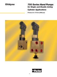
Catalogue HY17-8537/UKTechnical Data<strong>Directional</strong> <strong>Control</strong> <strong>Valve</strong>s<strong>K220LS</strong>Take-off ofuncopied loadpressure, PLGauge port forpump pressure,PXUTake-off ofcopied loadpressureforpump regulator,LSPump connection,P1 [26]Service port BTank connection, TM2 [92]Tank connection,TM1Take-off of pilotpressurefor externaluse, PSPump connection,P2 [32]Separate tankconnection forpilot tank, TP [40]Tank connection,T1 [25]Mid-inlet section,M1 [90]Pump connection, PMTank connection,T2 [24]Connection forpilot control ofcounter pressure,MP [24]Connection forhydraulic remotecontrol, PC(A- and B-port)Service port APressurePump inlet max. 350 bar (5075 psi) 1)Service ports max. 350 bar (5075 psi) 1)Pump regulator ∆p min. 18 bar (260 psi) 2)Compensator K3 ∆p min. 30 bar (435 psi) 2)Return line pressure (static) max. 15 bar (215 psi)1)Stated pressures are maximal absolute shock pressures at10 bar (145 psi) tank pressure2)Pressure drop from pump to valve max. 3 bar (45 psi)TemperatureOil temperature, working range+20 °C to +90 °C*(68 to 194 °F)FiltrationFiltration must be arranged so that Target Contamination Class20/18/14 according to ISO 4406 is not exceeded. For the pilotcircuit, Target Contamination Class 18/16/13 according to ISO4406 must not be exceeded.Hydraulic fluidsBest performance is obtained using mineral-base oil of highquality and cleanness in the hydraulic system.Hydraulic fluids of type HLP (DIN 51524), oil for automaticgearboxes Type A and engine oil type API CD can be used.Viscosity, working range15-380 mm 2 /s**Technical information in this catalogue is applicable at anoil viscosity of 30 mm 2 /s and temperature of 50 °C (122 °F)using nitrile rubber seals.* Product operating limits are broadly within the above range,but satisfactory operation within the specification may not beaccomplished. Leakage and response will be affected whenused at temperature extremes and it is up to the user to determineacceptability at these levels.** Performance efficiency will be reduced if outside the idealvalues. These extreme conditions must be evaluated by theuser to establish suitability of the products performance.5 Parker HannifinMobile <strong>Control</strong>s DivisionBorås, Sweden
Catalogue HY17-8537/UKTechnical Data<strong>Directional</strong> <strong>Control</strong> <strong>Valve</strong>s<strong>K220LS</strong>WeightThe weights given below are approximate, since they varysomewhat depending on valve configuration.Inlet section 11.4 kg 25.1 lbSpool section with PC spool actuator 13.1 kg 28.9 lbSpool section with EC spool actuator 14.5 kg 32.0 lbEnd section 4.1 kg 9.0 lbAdapter plate 8.3 kg 18.3 lbConnectionsP1, PM, T1, TM and the service ports A and B are fitted with socalledflange plane connections according to SAE J518. Fixingscrews for the flanges are available in two versions, UNC andmetric.Other connections are available in two versions:Connection thread type G is for flat seal according to ISO 228/1(BSP pipe thread).Connection thread type UN is for O-ring seal according toSAE J 1926/1.Connect. Location ThreadP1 inlet section Flange 1” (High pressure) 1)P2 end section G1 or 1 5/16 - 12 UN-2BT1 inlet section Flange 1 1/4” (Std pressure) 3)T2 inlet section G1 or 1 5/16 - 12 UN-2BA, B spool section Flange 1” (Std pressure) 2)A, B spool section Flange 3/4” (High pressure) 2)LS, PL inlet section G1/4 alt. 9/16 - 18 UNF-2BPX, PS inlet section G1/4 alt. 9/16 - 18 UNF-2BMP inlet section G1/4 alt. 9/16 - 18 UNF-2BLSP end section G3/8 alt. 9/16 - 18 UNF-2BT3 end section G1/4 alt. 9/16 - 18 UNF-2BPC spool section G1/4 alt. 9/16 - 18 UNF-2BTP end section G1/4 alt. 9/16 - 18 UNF-2BPM mid-inlet section Flange 1” (High pressure) 1)TM mid-inlet section Flange 1 1/4” (Std pressure) 1)TM2 mid-inlet section G1 or 1 5/16 - 12 UN-2B1)Screw M12 or 7/16-14 UNC, depth of thread ≥ 25 mm2)Screw M10 or 3/8 - 16 UNC, depth of thread ≥ 20 mm3)Screw M10 or 7/16-14 UNC, depth of thread ≥ 20 mm6 Parker HannifinMobile <strong>Control</strong>s DivisionBorås, Sweden
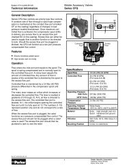
Catalogue HY17-8537/UKInlet Section<strong>Directional</strong> <strong>Control</strong> <strong>Valve</strong>s<strong>K220LS</strong>Pump connectionP1 [26]Tank connectionT1 [25]Counter pressure valveTank connection T2[24]Pressure reliefvalve PA1[16, 17]Copyingspool forload signalPilot filter [14]Load signal(not copied)connection PLGauge port, pumppressure PXLoad signal (copied)connection LSPilot pressuresupply for externaluse PSInlet section [12-29]The inlet section is equipped with a pump connection (P1) andtwo tank connections (T1, T2). It is also equipped with connectionsfor a copied load signal to the pump (LS), an uncopiedload signal to a subsequent valve (PL), a gauge point for measuringthe pump pressure (PX), a take-off of reduced pumppressurefor external pilot-oil supply (PS) and a connection fortransmitting the maximum load signal on to a subsequent valve(PL2).The inlet section also contains a number of other components,e.g. a copying spool for copying the load-signal pressure, a reducervalve with a built-in pressure relief valve for reducing thepump pressure to pilot pressure, a strainer to filter the pilot oiland a pressure relief valve that limits the maximum pressure ofthe valve. The strainer for the pilot oil can be replaced with anexternal filter.PA1Y1Direct-acting pressure relief valve PLC183 with veryfast opening sequence and good pressure characteristic.The replaceable PLC cartridge is factory set. Thecartridge has a replenishing function, which enablesoil to flow from the tank gallery to the pump gallery inthe event of underpressure in the pump circuit. See“Pressure setting [17]” for pressure values.Plug that replaces the pressure relief valve. The Y1plug blocks the connection between pump and tankcompletely.Pressure setting [17]Pressure settings for PA1 [16]The direct-acting pressure relief valve PA1 is deliveredfactory-set. The following standard pressure settings(in bar) are available: 50, 63, 80, 100, 125, 140, 160,175, 190, 210, 230, 240, 250, 260, 280, 300, 330 and350.PA1 should be set 20 bar above the maximum pressuresetting of the pump.See also technical data on page 5-6.Inlet section with PA1 pressure relief valve.7 Parker HannifinMobile <strong>Control</strong>s DivisionBorås, Sweden
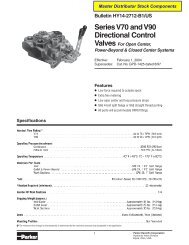
Catalogue HY17-8537/UKSpool Section<strong>Directional</strong> <strong>Control</strong> <strong>Valve</strong>s<strong>K220LS</strong>Spool section withPC spool actuatorCommon feed reducerMRM or MRC [75]Port relief valve, port B [76B]Port B [47]Port A [47]Port relief valve,port A [76A]Bleeder nippleSpool [69]Limiting of flow, Qset,QsetB [72]PC spool actuator [50]Bleeder nippleLimiting of flow, Qset,QsetA [72]Pilot pressure connection(P - B, A - T)Pilot pressure connection(P - A, B - T)Compensatordamping [67]Compensator [66]Spool section [45-89]The <strong>K220LS</strong> is a stackable directional valve and can be suppliedin combinations of 1 to 7 spool sections. Each section canbe equipped individually to incorporate a large number of differentfunctions. By means of function-adapted spools, spoolactuators, pressure relief valves, pressure compensators, etc.the valve can be optimized to suit different applications.PMTMConnections [04] and [47]The section service-port connections are the flange type accordingto SAE J 518. The fixing-screw threads are available intwo versions, UNC and M. Other connections on the section areof G type according to ISO 228/1 (for flat seal) or UN type accordingto SAE J 1926/1 (for O-ring seal). Please see page 3 fordimensions.MGMUUUFCSFCHFlanged connection with M threaded fixing screws.Other connections of G type.Flanged connection with M threaded fixing screws.Other connections of UN type.Flanged connection with UNC threaded fixing screws.Other connections of UN type.Spool section with service ports A and B according toSAE J518 Standard Pressure.Spool section with service ports A and B according toSAE J518 High Pressure.Mid-inlet section [90-99]In certain applications, e.g. the feeding of crawler-track motorson an excavator, there is a demand for high flow from two sectionsat the same time. This can be achieved by means of themid-inlet section Ml [90], which can be mounted anywhere inthe valve. Ideally, however, the high flows should be obtainedfrom the first and last spool sections, and the mid-inlet sectionshould be mounted between the last spool section and the endsection.Mid-inlet section with counter pressure valve.<strong>Valve</strong>s with mid-inlet sections can be fed with a pump flow of 2x 280 l/min. The mid-inlet section also contains two tank connectionsor, alternatively, one tank connection and a counterpressure valve (the same counter pressure valve that can beused in T2 [24].) There are two mounting plates on the mid-inletsection, one on each side. These should be used if the valve isto be mounted in any way other than with the service ports facingupward. See dimensional drawing on page 10.8 Parker HannifinMobile <strong>Control</strong>s DivisionBorås, Sweden
Catalogue HY17-8537/UKSpool Section<strong>Directional</strong> <strong>Control</strong> <strong>Valve</strong>s<strong>K220LS</strong>Feed reducer valve [75]Any section in the <strong>K220LS</strong> can be equipped with individualfeed reduction on service ports A and B.Feed reduction is used for functions in a system which requirea lower maximum pressure than the normal working pressureof the system. The reducer valve is adjustable and reducesthe feed pressure in the section to a pre-set level.By using a feed reducer valve, the feed pressure can belimited without consuming any more than a pilot flow (
Catalogue HY17-8537/UKDimensional Drawings<strong>Directional</strong> <strong>Control</strong> <strong>Valve</strong>s<strong>K220LS</strong>205178163(8.07)(7.01)(6.42)(inch)(4.09)104 (T2)(7.13)181(5.94)151(4.76)121(60)(2.36)96(3.78)16(0.63)60 max(2.36)102(4.15)48 (1.89)41 (PL2) (1.61)40 (YS) (1.57)38 (1.50)No. of L Lsections mm inch1 244 9.612 316 12.443 388 15.284 460 18.115 532 20.946 604 23.787 676 26.61(1.85)47 (LSP)(0.55)14 (XA)35 (XB)(1.38)LMid-inlet section100 (3.94)53 (2.09)72(2.83)145 (5.71)32Serviceport BP1Service port A(3.78)96 (PL2)84 (3.31)66 (2.60)(11.34)(10.00)288254(4.76)(1.26)121TM1T1(Ø0.53)Ø13,5(0.24)PM(10.23)260 max245(9.64)(5.94)151134(5.28)134(5.28)115(4.53)(2.36)6054(2.44)62(2.13)39(1.54)(0.91)23(0.55)14 (2X)(0.79)2044(1.73)613 (0.51)35 (1.38)53 (2.09)17(0.67)37 (1.45)61 (XA) (2.40)64 (2.52)74 (XB) (2.91)(3.86)167(6.57)98111 (T3, LSP)(4.37)TM2Lifting eye Ø15 (0.59)Toward inlet section10 Parker HannifinMobile <strong>Control</strong>s DivisionBorås, Sweden
Catalogue HY17-8537/UK<strong>Directional</strong> <strong>Control</strong> <strong>Valve</strong>s<strong>K220LS</strong>!WARNINGFAILURE OR IMPROPER SELECTION OR IMPROPER USE OF THE PRODUCTS AND/OR SYSTEMS DESCRIBEDHEREIN OR RELATED ITEMS CAN CAUSE DEATH, PERSONAL INJURY AND PROPERTY DAMAGE.This document and other information from Parker Hannifin Corporation, its subsidiaries and authorized distributors provideproduct and/or system options for further investigation by users having technical expertise. It is important that you analyze allaspects of your application, including consequences of any failure, and review the information concerning the product orsystem in the current product catalogue. Due to the variety of operating conditions and applications for these products orsystems, the user, through its own analysis and testing, is solely responsible for making the final selection of the products andsystems and assuring that all performance, safety and warning requirements of the application are met.The products described herein, including without limitation, product features, specifications, designs, availability and pricing, aresubject to change by Parker Hannifin Corporation and its subsidiaries at any time without notice.Offer of SalePlease contact your Parker representation for a detailed ”Offer of Sale”.11 Parker HannifinMobile <strong>Control</strong>s DivisionBorås, Sweden
Hydraulics GroupSales OfficesEuropeAustriaWiener NeustadtTel: +43 (0)2622 23501Fax: +43 (0)2622 66212BelgiumNivellesTel: +32 (0)67 280 900Fax: +32 (0)67 280 999Czech RepublicKlecanyTel: +420 284 083 111Fax: +420 284 083 112DenmarkBallerupTel: +45 4356 0400Fax: +45 4373 8431FinlandVantaaTel: +358 (0)9 4767 31Fax: +358 (0)9 4767 3200FranceContamine-sur-ArveTel: +33 (0)450 25 80 25Fax: +33 (0)450 03 67 37GermanyKaarstTel: +49 (0)2131 4016 0Fax: +49 (0)2131 4016 9199HungaryBudapestTel: +36 (06)1 220 4155Fax: +36 (06)1 422 1525IrelandDublinTel: +353 (0)1 293 9999Fax: +353 (0)1 293 9900ItalyCorsico (MI)Tel: +39 02 45 19 21Fax: +39 02 4 47 93 40The NetherlandsOldenzaalTel: +31 (0)541 585000Fax: +31 (0)541 585459NorwaySkiTel: +47 64 91 10 00Fax: +47 64 91 10 90PolandWarsawTel: +48 (0)22 863 49 42Fax: +48 (0)22 863 49 44PortugalLeca da PalmeiraTel: +351 22 9997 360Fax: +351 22 9961 527SlovakiaRef. Czech RepublicSpainMadridTel: +34 91 675 73 00Fax: +34 91 675 77 11SwedenSpångaTel: +46 (0)8 597 950 00Fax: +46 (0)8 597 951 10TurkeyMerter/IstanbulTel.: +90 212 482 91 06 or 07Fax: +90 212 482 91 10United KingdomWarwickTel: +44 (0)1926 317 878Fax: +44 (0)1926 317 855InternationalAustraliaCastle HillTel: +61 (0)2-9634 7777Fax: +61 (0)2-9899 6184CanadaMilton, OntarioTel: +1 905-693-3000Fax: +1 905-876-0788ChinaBeijingTel: +86 10 6561 0520Fax: +86 10 6561 0526Asia Pacific GroupHong Kong, KowloonTel: +852 2428 8008Fax: +852 2425 6896IndiaMumbaiTel: +91 22 7907081Fax: +91 22 7907080JapanTokyoTel: +(81) 3 6408 3900Fax: +(81) 3 5449 7201Latin America GroupBrazilTel: +55 12 3954-5100Fax: +55 12 3954-5266South AfricaKempton ParkTel: +27 (0)11-961 0700Fax: +27 (0)11-392 7213USACleveland (industrial)Tel: +1 216-896-3000Fax: +1 216-896-4031Lincolnshire (mobile)Tel: +1 847-821-1500Fax: +1 847-821-7600Parker Hannifin is the world’s premier supplier of motion and control systemsand solutions, with sales and manufacturing facilities throughout the world. Forproduct information and details of your nearest Parker sales office, visit us atwww.parker.com or call free on 00800 2727 5374.Catalogue HY17-8537/UKPDF 07/05© Copyright 2005Parker Hannifin CorporationAll rights reserved.