Tab 16.book - Piti Group
Tab 16.book - Piti Group
Tab 16.book - Piti Group

Create successful ePaper yourself
Turn your PDF publications into a flip-book with our unique Google optimized e-Paper software.
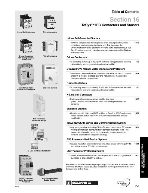
<strong>Tab</strong>le of ContentsSection 16TeSys IEC Contactors and StartersK-Line Mini ContactorsD-Line ContactorsU-Line Self-Protected StartersThe U-line self protected starters provide short-circuit protection, motorcontrol and overload protection in one unit. The line meets theUnderwriters Laboratory Standards for stand alone applications (UL 508Type E) and group motor installation meeting requirements of the NationalElectrical Code.16-42D-Line Contactorswith Spring TerminalConnectionsF-Line ContactorsD-Line ContactorsFor controlling motors up to 100 hp @ 460 volts. For applications requiringhigh reliability and long electrical and mechanical life.16-2GV2/GV3/GV7 Manual Motor Starters and ProtectorsThese horsepower rated manual starters include a manual motor controller,Class 10 bi-metallic overload relay and instantaneous magnetic tripmechanism in one compact unit.16-50F-Line ContactorsGV7 Manual MotorStarters and ProtectorsEnclosed StartersFor controlling motors up to 800 hp @ 460 volts. F-line contactors also offerhigh reliability and long electrical and mechanical life.16-3K-Line Mini ContactorsSmall, general purpose contactors ideal for light loads(up to 7.5 hp @ 460 volts) where small size and high reliability areconcerns.16-37Enclosed StartersLT3 ThermistorProtection RelaysAll starters are UL Listed and CSA certified in Type 1 or 12/3R enclosures.These devices feature INSTA-KITS prewired accessories for easymodification.TeSys QUICKFIT Wiring and Communication SystemUsing spring terminal technology, TeSys D-Line contactors and GV manualmotor protectors can be mounted and connected using no tools. Thesystem also allows for connection to networks via communicationsmodules (ordered from a separate catalog).AK5 Pre-assembled Busbar System16-3316-59U-Line Self-Protected StarterFor additional assistance selecting the proper products for your application, see theelectronic IEC Motor Data Calculator, available on www.SquareD.com under FreeSoftware and Online Tools.9/8/03Reduces installation and maintenance time. Ideal for use with Integral 18and 32 starters and GV2/LC1 combinations.LT3 Thermistor Protection RelaysDevices that continuously monitor the temperature of motors or generatorsby means of embedded PTC probes.16-6016-23IEC STYLE CONTACTORSAND STARTERS16GV2/GV3 ManualMotor Starters andProtectorsAK5 Pre-assembledBusbar System9/8/0316-1
www.SquareD.comFor the most up-to-date informationTeSys F-Line Contactors (IEC Rated)Non-Reversing, AC or DC Operating Coil3-Pole Contactors with AC and DC Operating CoilsLC1F115Single Phase115 VhpMaximum Horsepower Ratings230 Vhp. . . . . .200 VhpThree Phase230 Vhp460 Vhp575 VhpMaximum CurrentInductiveAC3AmperesResistiveAC1AmperesAuxiliaryContactsBuilt InN.O.N.C.CatalogNumberaACControlPriceDCControlPrice30 40 75 100 115 200 1c 0 LC1F115 $ 479. $ 479.40 50 100 125 150 250 1c 0 LC1F150 696. 696.50 60 125 150 185 275 1c 0 LC1F185 938. 938.60 75 150 175 265 350 1c 0 LC1F265 1179. 1179.75 100 200 250 330 400 1c 0 LC1F330 1621. 1621.100 125 250 300 400 500 1c 0 LC1F400 1874. 1874.150 200 400 500 500 700 1c 0 LC1F500 4970. 4970.250 300 600 800 630 1000 1c 0 LC1F630 6872. 6872.Current rated 780 1600 0 0 LC1F780 7788. 7788.. . . 450 800 900 800 1000 0 0 LC1F800 6676. 6676.2- and 4-Pole Contactors with AC and DC CoilsMaximum CurrentInductiveAC3AmperesResistiveAC1AmperesPower PolesAuxiliary ContactsBuilt InN.O. N.C. N.O. N.C.a Use voltage codes from the “Voltage Codes” table below to complete the catalog number.c This one normally open circuit contact is incorporated in the design of the standard coil.CatalogNumberaACControlPriceDCControlPrice115 200 4 0 1c 0 LC1F1154 $ 630. $ 630.150 250 4 0 1c 0 LC1F1504 825. 825.185 275 4 0 1c 0 LC1F1854 1439. 1439.265 350 4 0 1c 0 LC1F2654 1646. 1646.330 400 4 0 1c 0 LC1F3304 1846. 1846.400 520500 7002 0 1c 0 LC1F4002 1521. 1521.4 0 1c 0 LC1F4004 2133. 2133.2 0 1c 0 LC1F5002 4324. 4324.4 0 1c 0 LC1F5004 5617. 5617.630 100024001c1c00LC1F6302LC1F63045917.7582.5917.7582.780 1600 4 0 0 0 LC1F7804 9940. 9940.Voltage Codes (F-Line Only)ACContactor Hz 24 V 48 V 110 V 120 V 125 V 208 V 220 V 240 V 250 V 380 V 415 V 440 V 480 V 600 VF115, F15050 Hz B5 E5 F5 . . . . . . . . . M5 U5 . . . Q5 . . . . . . . . . . . .F18560 Hz B6 E6 F6 G6 . . . L6 M6 U6 . . . Q6 N5 . . . Q5 SCF265, F330 40–400 Hz B7 E7 F7 G7 . . . L7 M7 U7 . . . Q7 Q7 . . . S7 X7F400–F780 40–400 Hz . . . E7 F7 F7 . . . L7 M7 U7 . . . Q7 N7 . . . N7 X7dDCF115–F330 . . . BD ED FD . . . GD - MD . . . UD . . . . . . RD . . . . . .F400–F780 . . . . . . ED FD . . . GD - MD . . . UD . . . . . . RD . . . . . .d 600 volt coil not available for F780. The 600 V coils for the F400, F500 and F630 do not include an auxiliary contact for holding circuits.AC and DC Coil Voltages for F800 (includes built-in surge suppressor)Volts AC/DC 24 48 110 120 127 208 220 240 277 380 415 440 480 575 600 66050/60 Hz . . . . . . FW FW FW . . . MW MW . . . QW QW QW . . . . . . . . . . . .For Lugs see page 16-11.Dimensions . . . . . . . . . . . . . . . . . . . . . . . . . . . . . . . . . . . . pages 16-24–16-32Overload Relays . . . . . . . . . . . . . . . . . . . . . . . . . . . . . . . . pages 16-19–16-20Accessories . . . . . . . . . . . . . . . . . . . . . . . . . . . . . . . . . . . . . pages 16-6–16-13Replacement Coils . . . . . . . . . . . . . . . . . . . . . . . . . . . . . . pages 16-15–16-18For additional information, reference Catalog #8502CT9901R5/03.IEC STYLE CONTACTORSAND STARTERS16© 2003 Schneider ElectricAll Rights Reserved9/8/039/8/03I12DiscountSchedule16-3
TeSys D-Line Contactors (IEC Rated)3- and 4-Pole Reversing, AC or DC Operating Coilwww.SquareD.comFor the most up-to-date informationLC2D093-Pole Mechanically Interlocked ContactorsEach device is pre-wired with line and load side power wiring for reversing applicationsMaximum Horsepower RatingsSingle Phase Three Phase Inductive115 V 230 V 200 V 230 V 460 V 575 V AC3hp hp hp hp hp hp AmperesMaximum CurrentResistiveAC1AmperesBuilt InAuxiliaryContacts(per contactor) CatalogNumberabN.O. N.C.ACControlPriceDCControl0.5 1 2 2 5 7.5 9 20 1 1 LC2D09 $ 234. $317.1 2 3 3 7.5 10 12 25 1 1 LC2D12 317. 368.1 3 5 5 10 15 18 35 1 1 LC2D18 344. 400.2 3 7.5 7.5 15 20 25 40 1 1 LC2D25 374. 436.2 5 10 10 20 30 32 50 1 1 LC2D32 415. 503.3 5 10 10 30 30 40 60 1 1 LC2D40 565. . . .d3 7.5 15 15 40 40 50 70 1 1 LC2D50 596. . . .d5 10 20 20 50 50 65 80 1 1 LC2D65 778. . . .d7.5 15 30 30 60 60 80 110 1 1 LC2D80 1152. . . .d. . . . . . 30 40 75 100 115 175 1 1 LC2D115 1165. 1165.. . . . . . 40 50 100 125 150 200 1 1 LC2D150 1598. 1598.4-Pole Mechanically Interlocked ContactorsEach device is pre-wired with load side power wiringUtilization category AC-1Non-inductive loadsMaximum rated operational current(θ < 55°C [131°F])InstantaneousAuxiliary ContactsCatalogNumberaPriceA N.O. N.C.ACControlDCControl20 1 1 LC2DT20 c $ 234. $ 317.25 1 1 LC2DT25 c 317. 368.32 1 1 LC2DT32 c 419. 443.40 1 1 LC2DT40 c 456. 477.60 . . . . . . LC2D4004 c 720. . . .d80 . . . . . . LC2D65004 c 1361. . . .d125 . . . . . . LC2D80004 c 1406. . . .d200 . . . . . . LC2D115004 e 1391. 1391.a Use voltage codes from the “Voltage Codes” table on page 16-2 to complete the catalog number.b For LC2D09–LC2D32, electrical interlock can be included by adding a “V” to the end of the catalog number (ex: LC2DO9B7V). List price adder: $5.00.c Includes mechanical interlock without electrical contacts. Installer to complete wiring for electronically interlocking contactor operating coils by utilizinga N.C. auxiliary contact integrated in the contactor or optional LA1DN or LA8DN type auxiliary contact block.d For these items, order two non-reversing contactors and one mechanical interlock separately. See page 16-9 for selection.e Includes mechanical interlock (Type LA9D11502) with pre-wired electrical contacts for interlocking contactor operating coils.IEC STYLE CONTACTORSAND STARTERS16Dimensions. . . . . . . . . . . . . . . . . . . . . . . . . . . . . . . . . . . . .pages 16-24–16-32Overload Relays. . . . . . . . . . . . . . . . . . . . . . . . . . . . . . . . .pages 16-19–16-20Accessories . . . . . . . . . . . . . . . . . . . . . . . . . . . . . . . . . . . . .pages 16-6–16-13Replacement Coils. . . . . . . . . . . . . . . . . . . . . . . . . . . . . . .pages 16-15–16-18For additional information, reference Catalog #8502CT9901R5/03.16-49/7/05I12DiscountSchedule© 2005 Schneider ElectricAll Rights Reserved9/7/05
www.SquareD.comFor the most up-to-date informationTeSys Contactors (IEC Rated)3-Pole Reversing, AC or DC Operating CoilHOW TO ORDER:Components are available for customer assembly of F-line reversing contactors. For example, the followingcomponents must be ordered to build a 75 hp @ 460 V reversing contactor with a 120 V/60 Hz coil:LC1F265Quantity2 LC1F115G6 Contactors 2 x $463.006 DZ2FF1 Lugs (page 16-11) 6 x 6.302 LADN11 Auxiliary contacts 2 x 20.001 LA9FF976 Power connections 1 x 102.001 LA9FF970 Mechanical interlock 1 x 50.803-Pole ContactorsMaximum Horsepower Ratings Maximum Current Holding CircuitContact BuiltThree PhaseInto Coil200 Vhp230 Vhp460 Vhp575 VhpInductiveAC3AmperesResistiveAC1AmperesCatalogNumbera30 40 75 100 115 200 1 0 LC1F115 $ 479.40 50 100 125 150 250 1 0 LC1F150 696.50 60 125 150 185 275 1 0 LC1F185 938.60 75 150 200 265 350 1 0 LC1F265 1179.75 100 200 250 330 400 1 0 LC1F330 1621.100 125 250 300 400 500 1 0 LC1F400 1874.150 200 400 500 500 700 1 0 LC1F500 4970.250 300 600 800 630 1000 1 0 LC1F630 6872.Current rated 780 1600 0 0 LC1F780 7788.. . . 450 800 900 800 1000 0 0 LC1F800 6676.a Use coil voltage codes from the “Voltage Codes” table on page 16-3 to complete the contactor catalog number.N.O.N.C.PriceAuxiliary contact (electrical interlocking) - 2 must be purchasedFor use withNumberofContactsMaximum Numberof BlocksPer ContactorContactArrangementCatalogNumberLC1F1 1 1 - LADN10 $13.10to be ordered- 1 LADN01 13.10separately2 2 1 1 LADN11 20.702 - LADN20 20.704 2 2 2 LADN22 41.501 3 LADN13 41.504 - LADN40 41.50- 4 LADN04 41.503 1 LADN31 41.50(2) including 1 N.O. + 1 N.C. make-before-break 2 2 (2) LADC22 41.50PriceAccessoriesFor the assembly of three-pole reversing contactorsWith2 IdenticalContactors bSet Of Power ConnectionsCatalog Numberb For two different size contactors, refer to pages 16-12 and 16-13.PriceHorizontal MountingMechanical InterlockKit Catalog NumberLC1F115 LA9FF976 $ 93.00 LA9FF970 $53.00LC1F150 LA9F15076 93.00 LA9FF970 53.00LC1F185 LA9FG976 99.00 LA9FG970 53.00LC1F265 LA9FH976 146.00 LA9FJ970 76.00LC1F330 LA9FJ976 198.00 LA9FJ970 76.00LC1F400 LA9FJ976 198.00 LA9FJ970 76.00LC1F500 LA9FK976 270.00 LA9FJ970 76.00LC1F630, F800 LA9FL976 501.00 LA9FL970 76.00PriceIEC STYLE CONTACTORSAND STARTERSDimensions. . . . . . . . . . . . . . . . . . . . . . . . . . . . . . . . . . . . pages 16-24–16-32Overload Relays . . . . . . . . . . . . . . . . . . . . . . . . . . . . . . . . pages 16-19–16-20Accessories . . . . . . . . . . . . . . . . . . . . . . . . . . . . . . . . . . . . pages 16-6–16-13Replacement Coils . . . . . . . . . . . . . . . . . . . . . . . . . . . . . . pages 16-15–16-1816For additional information, reference Catalog #8502CT9901R5/03.© 2004 Schneider ElectricAll Rights Reserved7/16/047/16/04I12DiscountSchedule16-5
TeSys D-Line and F-Line Contactor AccessoriesAuxiliary Contacts, Time Delay, Mechanical Latchwww.SquareD.comFor the most up-to-date informationStandard, instantaneous auxiliary contact blocksSnap-OnMountingTo front ofLPtD40–D80, LCtDT20–DT40 (4P),LCtD09–D150aorTo right side ofLCtFTo front ofLPtD40–D80, LCtDT20–DT40 (4P),LCtD25 to D150orTo left side ofLCtFTo side ofLCtD09 to D150 only(not for use on F-LIne)Number ofContacts421CompositionN.O. N.C.Catalog NumberPrice2 2 LADN22b $41.501 3 LADN13b 41.504 0 LADN40b 41.500 4 LADN04b 41.503 1 LADN31b 41.502 2 LADC22 bc 41.501 1 LADN11b 20.702 0 LADN20b 20.700 2 LADN02b 20.701 0 LADN10d 13.100 1 LADN01 d 13.102 1 1 LAD8N11e 20.702 0 LAD8N20e 20.70a For low consumption coils, only one front-mounted two-contact block allowed. No side-mounted contact blocks allowed.b For spring terminal versions of these blocks, add a “3” to the end of the catalog number. For example, LADN223.c Including 1 N.O. + 1 N.C. make before break contacts.d This block cannot be added to the LC1D 09 to D32 contactors; a maximum of 2 blocks can be mounted on the LC1/LP1 D40 to D80 contactors only.e 1 block may be added to the left side of the LC1D 09 to D32, AC coils only; 1 block may be added to each side of the LC1D 40 to D80 contactors,AC coils only. Cannot be installed on D-Line contactors with DC coils.Front MountedAuxiliary Blocks(shown on D-LInecontactor)Instantaneous blocks with dust-tight auxiliary contacts (IP54) NEMA 12Snap-OnMountingTo front ofLPtD40–D80, LCtDT20–DT40 (4P),LCtD09 to D80orTo right side ofLCtFf Device supplied with 4 grounding terminal points.StandardContactsDusttightContacts Catalog Number PriceN.O. N.C. N.O. N.C.. . . . . . 2 . . . LA1DX20 $65.2 . . . 2 . . . LA1DZ40 82.1 1 2 . . . LA1DZ31 82.. . . . . . 2 . . . LA1DY20f 77.Pneumatic time delay contact blocksSnap-OnMountingTo front ofLPtD40–D80,LCtDT20–DT40 (4P),LCtD09 to D150orTo right side ofLCtFTime DelayContactsN.O. N.C.1 11 1g Scale range is expanded between 0.1 and 0.6 seconds on the dial for more accurate settings at the lower end of the range.h For spring terminal versions of these blocks, add a “3” to the end of the catalog number. For example, LADN223.i With switching time of 40 ms ± 15 ms between the opening of the N.C. contact to the closing of the N.O. contact.TypeOnenergization(on delay)Onde-energization(off-delay)Range ofTime DelayCatalogNumberPrice0.1 to 3 sg LADT0 $131.0.1 to 30 s LADT2 131.10 to 180 s LADT4 131.1 to 30 si LADS2 131.0.1 to 3 sg LADR0 131.0.1 to 30 s LADR2 131.10 to 180 s LADR4 131.IEC STYLE CONTACTORSAND STARTERSMechanical latch blocks with manual or electrical unlatch (D-Line only)Front snap-onmounting ontoj Does not include internal coil clearing contact.k See table below for coil voltages.ApplicationCatalog numberto be completedby the code correspondingto the coil voltageLCt/LPtD09 to D65 For silent operation and energy conservation LA6DK10jk $77.LC1 D80 to D150LP1 D80For silent operation and energy conservation LA6DK20jk 77.Coil Voltages for LA6DK mechanical latch blocksVolts 12 24 32/36 42/48 60/72 100 110/127 200/208 220/240 380/415 440/480 500/600AC or DC J B C E EN K F L M Q R SPriceDimensions . . . . . . . . . . . . . . . . . . . . . . . . . . . . . . . . . . . . pages 16-24–16-2616For additional information, reference Catalog #8502CT9901R5/03.16-66/14/04I12DiscountSchedule© 2004 Schneider ElectricAll Rights Reserved6/14/04
www.SquareD.comFor the most up-to-date informationTeSys D-Line Contactor AccessoriesCoil Suppressors, Cabling AccessoriesResistor/capacitor circuit (RC) for reduction of “electrical noise” in AC contactor coilsEffective protection of circuits sensitive to high frequency interference.• Limitation of transient voltage to 300% of nominal voltage maximum• Oscillating frequency limited to 400 Hz maximum• Slight increase in drop-out time (1.2 to 2 times normal)LA4DA1UInstalled by:Snapping into cavity on right sidewithout toolsbSnap-on mounting and connectionwithout tools to the contactorcoil terminalsScrew connectionto the contactorcoil terminalsMounting onLC1D09 to LC1D32 (3P)LCtDT20 to DT40 (4P),LCtD12 and D25 (4P)Pre-TeSys ContactorsLCtD40 to D150 (3 or 4P)LCtD40 to D115 (4P)Operating voltage50/60 HzCatalogNumberPrice24–28 V LAD4RCE $26.2050–127 V LAD4RCG 26.20110–240 V LAD4RCU 26.2024–48 V LA4DA1E 26.2050–127 V LA4DA1G 26.20110–240 V LA4DA1U 26.2024–48 V LA4DA2E 26.2050–127 V LA4DA2G 26.20110–240 V LA4DA2U 26.20380–415 V LA4DA2N 26.20Varistor (peak limiting) for reduction of “electrical noise” in AC or DC contactor coilsSimple component operating in AC and DC• Limitation of transient voltage value to 200% of nominal voltage maximum• Maximum reduction of transient voltage peaks• Slight increase in drop-out time (1.1 to 1.5 times normal)LA4DA2UInstalled by:Snapping into cavity on right sidewithout toolsbSnap-on mounting and connectionwithout tools to the contactorcoil terminalsScrew connectionto the contactorcoil terminalsScrew connectionto the contactorcoil terminalsMounting onLCtD09 to D32aTeSys contactorsLCtD09 to D32Pre-TeSys contactorsLCtD40 to D115 (3P or 4P)LCtD12, D25 (4P)LCtD40 to D115 (3P or 4P)Operating voltage50/60 Hz and DCa For DC coils 3-pole contactors are fitted with built-in surge suppression as standard .Catalog NumberPrice24–48 V LAD4VE $26.2050–127 V LAD4VG 26.20110–250 V LAD4VU 26.2024– 48 V LA4DE1E 26.2050–127 V LA4DE1G 26.20110–250 V LA4DE1U 26.2024–48 Vac LA4DE2E 26.2050–127 Vac LA4DE2G 26.20110–250 Vac LA4DE2U 26.2024–48 Vdc LA4DE3E 26.2050–127 Vdc LA4DE3G 26.20110–250 Vdc LA4DE3U 26.20Diode for reduction of “electrical noise” in DC contactor coilsEfficient protection for DC circuits:• No overvoltage or oscillating frequency• Polarized component• Increased drop-out time (6 to 10 times normal)LA4DC3ULAD4BB••Installed on theupper part by:Snap-on mounting and connectionwithout tools to the contactor coil terminalsScrew connection of wireto the contactor coil terminalsMounting onOperating voltageDCBidirectional peak limiting diode• Protection provided by limiting the transient voltage to 2 Uc max.• Maximum reduction of transient voltage peaksInstalled by:Snapping into cavity on right sideof contactor bScrew Mounting dCatalog Numberb Installing suppressor into the cavity makes the electrical connection. Overall width of contactor remains the same.c For LCtD09 through LCtD32 with DC or low consumption DC coils 3-pole contactors fitted with built-in bidirectional diode suppression as standard.d Mounting at the top of the contactor on coil terminals A1 and A2.Cabling AccessoriesUsageFor adapting existing wiring to a newproduct or for use with top mountaccessory.PriceLCtD12, D25 (4P) 24–250 V LA4DC1U $26.20LCtD40 to D80 (3P)LCtD40 to D80 (4P)Mounting on:LCtD09 to LCtD32 (3P)cLCtD40 to LCtD80Mounting onLC1D09 to D38LC1DT20 to DT60AC only24–250 V LA4DC3U 26.20Operating Voltage50/60 Hz and DCCatalog NumberPrice24 (AC only) LAD4TB $26.2072 (AC only) LAD4TS 26.2024 (AC only) LA4DB2B 26.2072 (AC only) LA4DB2S 26.2024 (DC only) LA4DB3B 26.2072 (DC only) LA4DB3S 26.20Operating voltage50/60 HzCatalog NumberPriceWithout coil suppression LAD4BB $23.00With coil24-48 V LAD4BBVE 23.00suppression 50-127 V LAD4BBVG 23.00(varistor)110-250 V LAD4BBVU 23.00IEC STYLE CONTACTORSAND STARTERS16For additional information, reference Catalog #8502CT9901R5/03.© 2004 Schneider ElectricAll Rights Reserved3/12/04I12DiscountSchedule16-73/12/04
TeSys D-Line Contactor AccessoriesElectronic Timers and Interface Moduleswww.SquareD.comFor the most up-to-date informationThe following accessories require use of cabling accessories (LAD4BBtt) for proper mounting. See page 16-7.Electronic Serial Timer ModulesThese solid state modules delay the energizing and de-energizing of the contactor coil.TypeOperational Voltagea24–250 Vac 100–250 Vac 24–250 Vac-dcOn-delay LC1D09–D32 LC1D40–D150 LP1D09–D32Time Delaya For 24 V operation, the contactor must be fitted with a 21 V coil: code Z5 for 50 Hz, Z6 for 60 Hz, ZD for DC.CatalogNumberPrice0.1–2 s LA4DT0U $82.001.5–30 s LA4DT2U 82.0025–500 s LA4DT4U 82.00LA4DFBInterface ModulesThese modules allow the contactor coils to be energized from low voltage and low current level signals. They comein mechanical relay and solid state versions. The relay plus manual operation versions include a lever for manuallyturning the contactor on and off. When a module receives a low level signal, it allows the separate sourced controlvoltage to flow to the contactor coil. It saves space and wiring time compared to conventional interposing relays.InterfaceTypeOperational Voltage24–250 Vac 100–250 Vac 24–250 VdcInputVoltageCatalogNumberRelayLC1D09–D150 LP1D09–D32 24 V LA4DFB $55.00LC1D09–D150 LP1D09–D32 48 V LA4DFE 55.00Relay Plus LC1D09–D150 LP1D09–D32 24 V LA4DLB 71.00Manual Operation LC1D09–D150 LP1D09–D32 48 V LA4DLE 71.00Solid State LC1D09–D32 LC1D40–D115 24 V LA4DWB 71.00PriceLA4DMUAutomatic-Manual-Stop Control ModulesThese modules allow for local and/or remote operation of the contactor coil. Each module includes a lever toswitch from automatic to manual operation and a dial to turn the contactor on and off.Operational VoltageCatalog24–100 Vac 100–250 Vac 24–100 Vdc 100–250 VdcNumberPriceLC1D09–D150 . . . LP1D09–D32 . . . LA4DMK $35.00. . . LC1D09–D150 . . . LP1D09–D32 LA4DMU 35.00IEC STYLE CONTACTORSAND STARTERS16LADLVRTA1A2LADLVRTA1E1LAD4BBContactors 32 A and lessA1E1Contactors 40 A–80 AE21.8547A2E21.2532A2SEMI F47 Low Voltage Ride Through ModuleBy ensuring SEMI F47 compliance of AC powered IEC contactors and relays, the low voltage ride throughmodules can be used to increase the voltage sag immunity of semiconductor processing equipment. Thesemodules make it possible for AC powered TELEMECANIQUE contactors and relays to exceed the requirementsof SEMI F47, both in the magnitude and duration of a voltage sag event—even with accessories such as auxiliarycontact blocks and pneumatic timers.The low voltage ride through modules can be used with TELEMECANIQUE contactors from 9 A through 80 A, aswell as the CAD series of control relays.For use on: Catalog Number PriceLC1DttB7, CADttB7 LADLVRT24Vb $124.00LC1DttG7, CADttG7 LADLVRT120Vb 124.00LC1DttLE7, CADttLE7 LADLVRT208Vb 124.00Top mount bracket (required when using above modules) LAD4BBc 23.00Fuse LA9D941 60.00b The low voltage ride through module can be used with all TeSys control relays with 24 Vac, 120 Vac or 208 Vac dual frequency coils.c LAD4BB must be used when the low voltage ride through module is being used with contactors 32 A and less, and TeSys CAD Series of ControlRelays.For additional information, reference Catalog #8502CT9901R5/03.16-83/12/04I12DiscountSchedule© 2004 Schneider ElectricAll Rights Reserved3/12/04
www.SquareD.comFor the most up-to-date informationAccessoriesTeSys D-Line Reversing ContactorsContactors Mechanical interlock Set of power connectionsReversing contactors comprisingtwo identical, horizontallymounted contactors:Without electricalinterlockWith incorporatedelectrical interlock(2 N.C. contacts)Reversing contactorsfor motor controlFour polecontactorsLC1D09, LC1D12, LC1D18,LC1D25, LC1D32LC1DT20, LC1DT25, LC1DT32,LC1DT40Catalog Number Price Catalog Number Price Catalog Number Price Catalog Number PriceLAD9R1 $32.10 LAD9R1V $45.50 Included with kit Not AvailableLADT9R1 $36.90 LADT9R1V $50.30 Not Available Included with kitLC1D40LC1D50LC1D/LP1D65LA9D50978 $31.70 LA9D4002 $45.90 LA9D6569 $53.00 LA9D6570 $63.00LC1D80 AC LA9D50978 $31.70 LA9D4002 45.90 LA9D8069 $65.00 LA9D8070 $79.00LC1D80 DC LA9D80978 $31.70 LA9D8002 65.00 LA9D8069 $65.00 LA9D8070 $79.00LC1D115 and LC1D150 Not Available LA9D11502 78.00 LA9D11569 129.00 LA9D11571 (3P) 53.00LA9D11570 (4P)(D115 only)53.00Dimensions . . . . . . . . . . . . . . . . . . . . . . . . . . . . . . . . . . . . . . . . . . .page 16-27For additional information, reference Catalog #8502CT9901R5/03.IEC STYLE CONTACTORSAND STARTERS16© 2004 Schneider ElectricAll Rights Reserved3/9/04I12DiscountSchedule16-9
www.SquareD.comFor the most up-to-date informationLA9F980LA9D09981Suppressor BlocksAccessoriesTeSys F-Line ContactorsOperating limit: up to 220 V, 50/60 Hz coilsDescription For Use Catalog Number PriceWith coils LX1FF, FG, FH, F115, F185, F265, F330 LA9F980 $21.80Suppressor block(clip-on mounting to coil)With coilsLX1FJ, FK, FL, FX, F400, F500, F630, F780LX9FF, FG, FH, F115, F185, F265, F330LA9D09980 20.70Mounting bracket (for 35 mm DIN rail or panel mounting) for suppressor block LA9D09981 5.50Lugs—3-PoleContactorType LC1Lug KitCatalog NumberCable Size AL/CUF115 DZ2FF6 14 to 2/0 $ 39.30F150, F185 DZ2FG6 6 to 3/0 65.00F265, F330 DZ2FH6 6 to 300 MCM 65.00F400 DZ2FJ6 4 to 500 MCM 65.00F500 DZ2FK6 2 X 2 to 600 MCM 131.00F630, F800 DZ2FL6 3 X 2 to 600 MCM 164.00F780 DZ2FX6 4 X 1/0 to 750 MCM 164.00Lugs for LC1F must be ordered separately. Each kit consists of six (6) lugs. Mounting hardware (screws, washers, nuts) are provided with the contactor,not the lugs.PriceLugs—2 and 4-PoleContactorLug KitQty. RequiredAL/CUType LC1Catalog Number 2-Pole 4-PoleCable SizePriceF115 DZ2FF1 4 8 14 to 2/0 $ 6.50F150, F185 DZ2FG1 4 8 6 to 3/0 11.00F265, F330 DZ2FH1 4 8 6 to 300 MCM 11.00F400 DZ2FJ1 4 8 4 to 500 MCM 11.00F500 DZ2FK1 4 8 2 X 2 to 600 MCM 21.80F630 DZ2FLa a N/A 3 X 2 to 600 MCM aF780 DZ2FX1 4 8 4 X 1/0 to 750 MCM 28.30Lugs for LC1F contactors and overload relays must be ordered separately. Each kit consists of one (1) lug. Mounting hardware (screws, washers, nuts)are provided with the contactors, not the lugs.a For 2-pole F630 contactors, order 2 DZ2FL1 (L1 and T2), and 2 DZ2FL3 (L2 and T1). For 4-pole F6304, order 2 DZ2FL1 (L1 and T4), 4 DZ2FL2(L2, T2, L3, T3) and 2 DZ2FL3 (L4 and T1). All three are priced at $27.30 each.Power Terminal Protection ShroudsThese clear plastic protective shrouds are an effective means to meet international touch-safe requirements forpower terminals. They are designed to be used with power cables that have been bolted to the terminal.LA9F70tNote: The protection shrouds do not attach to contactors or overloads utilizing DZ2F lug kits.For Use With 2-, 3-, And 4-pole Contactors Number of Shrouds Per Set Set Catalog Number PriceLC1F115 6 LA9F701 $ 42.40LC1F150, F185CR1F150, F1856 LA9F702 61.00LC1F225, F265, F330, F400 and F4002, F500 and F5002CR1F265, F400 and F5006 LA9F703 82.00LC1F630, F6302 and F800CR1F6306 LA9F704 93.00LC1F1154 8 LA9F706 58.00LC1F1504 and F1854 8 LA9F707 80.00LC1F2254, F2654, F3304, F4004, F5004 8 LA9F708 111.00LC1F6304 8 LA9F709 120.00Dimensions . . . . . . . . . . . . . . . . . . . . . . . . . . . . . . . . . . . . pages 16-28–16-29For additional information, reference Catalog #8502CT9901R5/03.IEC STYLE CONTACTORSAND STARTERS16© 2003 Schneider ElectricAll Rights Reserved9/8/039/8/03I12DiscountSchedule16-11
AccessoriesTeSys F-Line Reversing Contactorswww.SquareD.comFor the most up-to-date informationHorizontal mounting Mechanical interlocks Set of power connectionsReversers assembledwith two contactorsof identical ratings:LC1F115 or F1154LC1F150 or F1504LC1F185 or F1854LC1F265 or F2654LC1F330 or F3304LC1F400 or F4004LC1F500 or F5004LC1F630 or F6304LC1F800LA9Ft970A1A2Reversing contactors3-poleLA9Ft976L1 L2 L31 3 5 1 3 52 4 6 2 4 6U V WA1A2A1A2Changeover3-pole 4-poleLA9Ft982 LA9Ft9771N 1L2 2L1 2L31L3 1L1 2L2 2N1 3 5 7 1 3 5 72 4 6 8 2 4 6 8L1 L2 L3 NA1A2LA9Ft982Vertical mountingReversers assembledwith two contactorsof identical ratings:LC1F115 or F1154LC1F150 or F1504LC1F185 or F1854LC1F265 or F2654LC1F330 or F3304LC1F400 or F4004LC1F500 or F5004LC1F630 or F6304LC1F800Mechanical interlocksLA9FF4FLA9FG4GLA9FH4HLA9FJ4JLA9FK4KLA9FL4LLC1F780LC1F7804LA9FX970 (3-pole reverser)LA9FX971 (4-pole transfer)IEC STYLE CONTACTORSAND STARTERS16Reversers assembledwith two contactorsof different ratings:LC1F115 or F1154LC1F150 or F1504LC1F185 or F1854LC1F265 or F2654LC1F330 or F3304LC1F400 or F4004LC1F500 or F5004LC1F630 or F6304NOTE: Lower contactor must have equal or lower current rating.LA9FH4HLA9FJ4FLA9FK4FLA9FL4FLA9FH4GLA9FJ4GLA9FL4GLA9FL4GLA9FJ4HLA9FK4HLA9FL4HLA9FK4JLA9FL4JLA9FL4KFor additional information, reference Catalog #8502CT9901R5/03.9/8/0316-12© 2003 Schneider ElectricAll Rights Reserved9/8/03
www.SquareD.comFor the most up-to-date informationAccessoriesTeSys F-Line Reversing ContactorsComponent parts for the assembly of F-Line 3-pole reversing contactorsWith2 IdenticalContactors aHorizontal MountingSet of Power ConnectionsCatalog NumberPriceMechanical Interlock KitCatalog NumberLC1F115 LA9FF976 $106.00 LA9FF970 $ 53.00LC1F150 LA9F15076 96.00 LA9FF970 53.00LC1F185 LA9FG976 113.00 LA9FG970 53.00LC1F265 LA9FH976 151.00 LA9FJ970 76.00LC1F330 LA9FJ976 225.00 LA9FJ970 76.00LC1F400 LA9FJ976 225.00 LA9FJ970 76.00LC1F500 LA9FK976 306.00 LA9FJ970 76.00LC1F630 or F800 LA9FL976 568.00 LA9FL970 76.00Vertical MountingLC1F115 or F150 d . . . LA9FF4F $ 97.00LC1F185 d . . . LA9FG4G 113.00LC1F265 d . . . LA9FH4H 126.00LC1F330 d . . . LA9FJ4J 149.00LC1F400 d . . . LA9FJ4J 149.00LC1F500 d . . . LA9FK4K 149.00LC1F630 or F800 d . . . LA9FL4L 149.00LC1F780 b . . . LA9FX970 b 508.00Component parts for the assembly of F-Line 3-pole or 4-pole transfer contactorsHorizontal Mounting Three-Pole Four-Pole Price PriceLC1F115/4 LA9FF982 LA9FF977 $ 53.00 LA9FF970 $ 53.00LC1F150/4 LA9F15082 LA9F15077 53.00 LA9FF970 53.00LC1F185/4 LA9FG982 LA9FG977 53.00 LA9FG970 53.00LC1F265/4 LA9FH982 LA9FH977 83.00 LA9FJ970 76.00LC1F330/4 LA9FJ982 LA9FJ977 113.00 LA9FJ970 76.00LC1F400/4 LA9FJ982 LA9FJ977 113.00 LA9FJ970 76.00LC1F500/4 LA9FK982 LA9FK977 154.00 LA9FJ970 76.00LC1F630/4 LA9FL982 LA9FL977 233.00 LA9FL970 76.00Vertical MountingLC1F115/4 d . . . . . . LA9FF4F $ 97.00LC1F185/4 d . . . . . . LA9FG4G 113.00LC1F265/4 d . . . . . . LA9FH4H 149.00LC1F330/4 d . . . . . . LA9FJ4J 149.00LC1F400/4 d . . . . . . LA9FJ4J 149.00LC1F500/4 d . . . . . . LA9FK4K 149.00LC1F630/4 d . . . . . . LA9FL4L 149.00LC1F780/4 c . . . . . . LA9FX970 c 508.00PriceVertical mounting of 2 contactors of different ratings aUpper ContactorLower ContactorMechanical Interlock KitCatalog NumberPriceLC1F185 or 1854 LC1F115/150 or 1154/1504 LA9FG4F $113.00LC1F265 or 2654 LC1F115/150 or 1154/1504 LA9FH4F 126.00LC1F330 or 3304 LC1F185/1854 or 265/265A LA9FH4G 126.00LC1F115/150 or 1154/1504 LA9FJ4F 126.00LC1F400 or 4004LC1F185 or 1854 LA9FJ4G 126.00LC1F265/2654 or 330/330A LA9FJ4H 149.00LC1F115/150 or 1154/1504 LA9FK4F 149.00LC1F500 or 5004LC1F185 or 1854 LA9FK4G 126.00LC1F265/2654 or 330/330A LA9FK4H 149.00LC1F400 or 4004 LA9FK4J 149.00LC1F115/150 or 1154/1504 LA9FL4F 116.00LC1F185 or 1854 LA9FL4G 126.00LC1F630, 6304 orLC1F800LC1F265/2654 or 330/330A LA9FL4H 149.00LC1F400 or 4004 LA9FL4J 149.00LC1F500 or 5004 LA9FL4K 149.00a With identical or different numbers of poles.b Double mechanical interlock with 2 mechanical links and 3 power connection bars.c Double mechanical interlock with 2 mechanical links and 4 power connection bars.d Power connection to be assembled by the customer, except for contactors LC1F780 and F7804.For additional information, reference Catalog #8502CT9901R5/03.IEC STYLE CONTACTORSAND STARTERS16© 2003 Schneider ElectricAll Rights Reserved9/8/039/8/03I12DiscountSchedule16-13
Replacement PartsTeSys F-Line Contact Kits, Arc Chamberswww.SquareD.comFor the most up-to-date informationFor useon contactorsCatalogNumberPriceLA5FG431LA5F11550Replacement contact sets aTwo-poleThree-poleFour-poleArc chambersTwo-poleThree-poleFour-poleLC1F4002 2 poles LA5F400802 $ 717.00LC1F5002 2 poles LA5F500802 1111.00LC1F6302 2 poles LA5F630802 1651.00LC1F115, F150 3 poles LA5FF431 239.00LC1F185 3 poles LA5FG431 418.00LC1F265 3 poles LA5FH431 793.00LC1F330, F400 3 poles LA5F400803 1076.00LC1F500 3 poles LA5F500803 1589.00LC1F630 3 poles LA5F630803 2488.00LC1F780 1 pole LA5F780801d 1651.00LC1F800 3 poles LA5F800803 2488.00LC1F1504, F1154 4 poles LA5FF441 318.00LC1F1854 4 poles LA5FG441 549.00LC1F2654 4 poles LA5FH441 966.00LC1F3304, F400, F4004 4 poles LA5F400804 1435.00LC1F5004 4 poles LA5F500804 2461.00LC1F6304 4 poles LA5F630804 3304.00LC1F7804 1 pole LA5F780801d 1651.00LC1F4002 2 poles LA5F400250 $ 280.00LC1F5002 2 poles LA5F500250 305.00LC1F6302 2 poles LA5F630250 431.00LC1F115 3 poles LA5F11550 90.00LC1F150 3 poles LA5F15050 101.00LC1F185 3 poles LA5F18550 179.00LC1F265 3 poles LA5F26550 269.00LC1F330 3 poles LA5F33050 287.00LC1F400 3 poles LA5F40050 305.00LC1F500 3 poles LA5F50050 341.00LC1F630 3 poles LA5F63050 646.00LC1F780 1 pole LA5F780150d 431.00LC1F800 3 poles LA5F80050 750.00LC1F1154 4 poles LA5F115450 119.00LC1F1504 4 poles LA5F150450 131.00LC1F1854 4 poles LA5F185450 209.00LC1F2654 4 poles LA5F265450 299.00LC1F3304 4 poles LA5F330450 508.00LC1F4004 4 poles LA5F400450c 573.00LC1F5004 4 poles LA5F500450c 610.00LC1F6304 4 poles LA5F630450b 861.00LC1F7804 1 pole LA5F780150d 431.00a Supplied per pole are: 2 fixed contacts, 1 moving contact, 2 deflectors, 1 backplate, mounting screws and washers.b Comprises single-pole components.c Comprises 2-pole components.d 2 identical components per pole are supplied.IEC STYLE CONTACTORSAND STARTERS16For additional information, reference Catalog #8502CT9901R5/03.16-149/8/03I12DiscountSchedule© 2003 Schneider ElectricAll Rights Reserved9/8/03
www.SquareD.comFor the most up-to-date informationLX1D2For LC1D09–D32, LC1DT20–40 (TeSys )Contactors and CAD RelaysRated Nominal Voltage Catalog Number 50/60 Hz Price12 LXD1J721aLXD1Z724 LXD1B7$26.2032 LXD1C736 LXD1CC742 LXD1D748 LXD1E760 LXD1EE726.20100 LXD1K7110 LXD1F7115 LXD1FE7120 LXD1G7127 LXD1FC726.20200 LXD1L7208 LXD1LE7220/230 LXD1M7230 LXD1P7230/240 LXD1U726.20277 LXD1W7380/400 LXD1Q7400 LXD1V7415 LXD1N7440 LXD1R726.20480 LXD1T7575 LXD1SC7600690LXD1X7LXD1Y726.20SpecificationsAverage consumption:Inrush (inductance .75)Sealed (inductance .3)Operating range@ 60° C70 VA7 VA80–110% of nominal @ 50 Hz85–110% of nominal @ 60 Hza Voltage for special coils fitted in contactors with serial timer modules,with 24 V supply.Repair PartsD-Line AC CoilsFor LC1D09, D12, D18 ContactorsFor old style contactors where the catalog number includes the auxilarycontact arrangement (ex. LC1D0901F7)Rated NominalVoltageVCatalogNumber50 HzCatalogNumber60 HzCatalogNumber50/60 Hz21 b LX1D2Z5 LX1D2Z6 LX1D2Z724 LX1D2B5 LX1D2B6 LX1D2B732 LX1D2C5 . . . . . .42 LX1D2D5 . . . LX1D2D748 LX1D2E5 LX1D2E6 LX1D2E7110 LX1D2F5 LX1D2F6 LX1D2F7120 . . . LX1D2G6 LX1D2G7127 LX1D2G5 . . . . . .208 . . . LX1D2L6 . . .220 LX1D2M5 LX1D2M6 LX1D2M7230 LX1D2P5 . . . LX1D2P7240 LX1D2U5 LX1D2U6 LX1D2U7256 LX1D2W5 . . . . . .277 . . . LX1D2W6 . . .380 LX1D2Q5 LX1D2Q6 LX1D2Q7400 LX1D2V5 . . . LX1D2V7415 LX1D2N5 . . . LX1D2N7440 LX1D2R5 LX1D2R6 LX1D2R7480 . . . LX1D2T6 . . .500 LX1D2S5 . . . . . .575 . . . LX1D2S6 . . .600 . . . LX1D2X6 . . .660 LX1D2Y5 . . . . . .SpecificationsAverageconsumptionInrush(inductance .75)Sealed(inductance .3)Operating rangeat θ ≤ 55°C /131°F50 Hz 60 Hz 50/60 Hz60 VA 70 VA7 VA 7.5 VA80–110 %of nominalvoltage80–110%of nominalvoltage70 VA at 50or 60 Hz8 VA at 50or 60 HzPrice$26.2026.2026.2026.2026.2085–110%of nominal voltageFor LC1D25, D32—For old style contactors where the catalog number includes the auxiliary contact arrangement (ex: LC1D2510F7)SpecificationsRatedNominal Voltage (V)Catalog Number50 Hzb For use in 24 volt applications involving serial timer modules. Refer to page 16-8.Catalog Number60 HzCatalog Number50/60 Hz21b LX1D4Z5 LX1D4Z6 LX1D4Z724 LX1D4B5 LX1D4B6 LX1D4B732 LX1D4C5 . . . . . .42 LX1D4D5 . . . LX1D4D748 LX1D4E5 LX1D4E6 LX1D4E7110 LX1D4F5 LX1D4F6 LX1D4F7120 . . . LX1D4G6 LX1D4G7127 LX1D4G5 . . . . . .208 . . . LX1D4L6 . . .220 LX1D4M5 LX1D4M6 LX1D4M7230 LX1D4P5 . . . LX1D4P7240 LX1D4U5 LX1D4U6 LX1D4U7256 LX1D4W5 . . . . . .277 . . . LX1D4W6 . . .380 LX1D4Q5 LX1D4Q6 LX1D4Q7400 LX1D4V5 . . . LX1D4V7415 LX1D4N5 . . . LX1D4N7440 LX1D4R5 LX1D4R6 LX1D4R7480 . . . LX1D4T6 . . .500 LX1D4S5 . . . . . .575 . . . LX1D4S6 . . .600 . . . LX1D4X6 . . .660 LX1D4Y5 . . . . . .Average consumption- Inrush (inductance .75)- Sealed (inductance .3)Operating rangeat θ ≤ 55°C / 131°F50 Hz 60 Hz 50/60 Hz90 VA7.5 VA80–110% ofnominal voltage100 VA8.5 VA80–110% ofnominal voltage100 VA at 50 or 60 Hz8.5 VA at 50 or 60 Hz85–110% ofnominal voltagePrice$36.0036.0036.0036.0036.00IEC STYLE CONTACTORSAND STARTERSFor additional information, reference Catalog #8502CT9901R5/03.16© 2004 Schneider ElectricAll Rights Reserved3/9/043/9/04I12DiscountSchedule16-15
Repair PartsD- and F-Line AC Coilswww.SquareD.comFor the most up-to-date informationFor LC1D40, D50, D65, D80aRatedNominal VoltageVCatalogNumber50 HzCatalogNumber60 HzCatalog Number50/60 HzPrice24 LX1D6B5 LX1D6B6 LX1D6B7 $41.5032 LX1D6C5 . . . . . . 41.5042 LX1D6D5 . . . LX1D6D7 41.5048 LX1D6E5 LX1D6E6 LX1D6E7 41.50110 LX1D6F5 LX1D6F6 LX1D6F7 41.50120 . . . LX1D6G6 LX1D6G7 41.50127 LX1D6G5 . . . . . . 41.50208 . . . LX1D6L6 LX1D6LE7 41.50220 LX1D6M5 LX1D6M6 LX1D6M7 41.50230 LX1D6P5 . . . LX1D6P7 41.50240 LX1D6U5 LX1D6U6 LX1D6U7 41.50256 LX1D6W5 . . . . . . 41.50277 . . . LX1D6W6 . . . 41.50380 LX1D6Q5 LX1D6Q6 LX1D6Q7 41.50400 LX1D6V5 . . . LX1D6V7 41.50415 LX1D6N5 . . . LX1D6N7 41.50440 LX1D6R5 LX1D6R6 LX1D6R7 41.50480 . . . LX1D6T6 . . . 41.50500 LX1D6S5 . . . . . . 41.50575 . . . LX1D6S6 . . . 41.50600 . . . LX1D6X6 . . . 41.50660 LX1D6Y5 . . . . . . 41.50For LC1D115, D150bRatedNominal VoltageVCatalog Number50 HzCatalog Number60 HzCatalog Number50/60 HzPrice24 LX1D8B5 LX1D8B6 LX1D8B7 $78.0032 LX1D8C5 . . . LX1D8C7 78.0042 LX1D8D5 . . . LX1D8D7 78.0048 LX1D8E5 LX1D8E6 LX1D8E7 78.00110 LX1D8F5 LX1D8F6 LX1D8F7 78.00115 LX1D8FE5 . . . LX1D8FE7 78.00120 . . . LX1D8G6 LX1D8G7 78.00127 LX1D8FC5 . . . LX1D8FC7 78.00208 . . . LX1D8LG LX1D8L7 78.00220/230 LX1D8M5 LX1D8M6 LX1D8M7 78.00230 LX1D8P5 . . . LX1D8P7 78.00240 LX1D8U5 LX1D8U6 LX1D8U7 78.00277 . . . LX1D8W6 LX1D8W7 78.00380/400 LX1D8Q5 LX1D8Q6 LX1D8Q7 78.00400 LX1D8V5 . . . LX1D8V7 78.00415 LX1D8N5 . . . LX1D8N7 78.00440 LX1D8R5 LX1D8R6 LX1D8R7 78.00480 . . . LX1D8T6 LX1D8T7 78.00500 LX1D8S5 . . . LX1D8S6 78.00Specification 50 Hz 60 Hz 50/60 HzAverage consumption- inrush (inductance .75)- sealed (inductance .3)200 VA20 VA220 VA22 VA245 VA at 50 or 60 Hz26 VA at 50 or 60 HzOperating rangeat θ ≤ 55°C / 131°F80–110% ofnominal voltage80–110% ofnominal voltage85–110% ofnominal voltageSpecification 50 Hz 60 Hz 50/60 HzAverage consumption- inrush (inductance .3)- sealed (inductance .3)300 VA22 VA300 VA22 VA350 Va18 VaOperating range 85–110% of 85–110% ofA7 θ ≤ 55°C / 131°F nominal voltage nominal voltagea For old style and new TeSys style contactors where the catalog number may or may not include the auxiliary contact arrangement. (ex: LC1D4010F7 or LC1D40F7).b For old style and new TeSys style contactors where the catalog number may or may not include the auxiliary contact arrangement; (ex: LC1D11500F7 or LC1D115F7).80–115% ofnominal voltage- inrush (.9)- sealed (.9)IEC STYLE CONTACTORSAND STARTERS16For LC1F115, F150, F185, F265, F330, F400, F500, F630, F780, F800LX1 coils are the standard coils that are included when a voltage code is added to the contactor part number. The LX9 coils may be ordered separatelyfor special applications. LX9 coils do not include a built-in normally open holding circuit contact; a separate auxiliary contact block with a N.O. contactshould be added to the contactor. Both the LX1 and LX9 coils can be used on the previous F-line contactors.DeviceTypeF115–F150F185F265–F330F400dF500dF630dHzCatalogt Catalog Number SuffixNumber 24 V 48 V 110 V 120 V 208 V 220 V 240 V 277 V 380 V 415 V 440 V 480 V 600 V Price50 LX1FFt 024 048 110 127 200 220 240 264 380 415 415 500 600 $ 78.0060 LX1FFt 020 040 092 095 162 184 187 220 316 340 360 380 475 78.0040–400 LX9FFt . . . 048 110 127 200 220 220 260 380 415 415 500 . . . 78.0050 LX1FGt 024 048 110 127 200 220 240 264 380 415 415 450 600 108.0060 LX1FGt 020 040 092 095 162 184 187 220 316 340 360 380 475 108.0040–400 LX9FGt . . . 048 110 127 200 220 220 260 380 415 415 500 . . . 108.0040–400 LX1FHt 0242 0482 1102 1272 2002 2202 2402 2772 3802 3802 4402 5002 6002 138.0040–400 LX9FHt . . . 0482 1102 1272 2002 2202 2402 2772 3802 3802 . . . 5002 . . . 138.0040–400 LX1FJt . . . 048 110 110 200 220 240 280 380 415 415 415 600 287.0040–400 LX9FJt f 910 917 925 925 930 931 932 932 936 936 937 937 . . . 287.0040–400 LX1FKt . . . 048 110 110 200 220 240 280 380 415 415 415 600 360.0040–400 LX9FKt f 910 917 925 925 930 931 932 932 936 936 937 937 . . . 360.0040–400 LX1FLt . . . 048 110 110 200 220 240 260 380 415 415 415 600 398.0040–400 LX9FLt f 910 917 924 925 930 930 931 932 935 936 936 937 . . . 483.00F780, FX c 40–400 LX1FXt . . . . . . 110 110 200 220 220 280 380 415 415 415 . . . 795.00F800 50/60 LX4F8te . . . . . . FW FW . . . MW MW . . . QW QW QW . . . . . . 725.00c LClF780 contactors operate on 2 coils as a set. The LX1FX part number includes both coils.d The 600 V coils for the F400, F500 and F630 do not include an auxiliary contact for holding circuits.e Also requires rectifier DR5TE4U for 110 V–240 V coils, DR5TE4S for 380 V–440 V coils. See table below for pricing.f Coil circuit requires a separately mounted rectifier. Order from table below.Coil Rectifier Catalog Number PriceLX9Ft910 DR5TF4V $75.00LX9Ft917 DR5TF4V 75.00LX9Ft925 DR5TE4U 75.00LX9Ft926 DR5TE4U 75.00LX9Ft931 DR5TE4U 75.00LX9Ft936 DR5TE4S 75.00LX9Ft937 DR5TE4S 75.00LX9Ft938 DR5TE4S 75.00Application Note on Contactor Drop-out Times:Contactors using LX1, FH, FJ, FK, FL, and FX coils have longer drop-out times.For critical applications such as emergency stop functions:• Select a fast drop-out coil (LX9), or• Use a maintained contact Stop button, or• Use an interposing relay.LX1D6For additional information, reference Catalog #8502CT9901R5/03.16-163/9/04I12DiscountSchedule© 2004 Schneider ElectricAll Rights Reserved3/9/04
www.SquareD.comFor the most up-to-date informationRepair PartsD-Line and F-Line, AC and DC CoilsF-Line DC CoilsFor LC1F115, F150, F185, F265, F400, F500, F630, F780, F800LX4 coils are the standard coils when a voltage code is added to the part number. The LX9 coils may be ordered separately for special applications.LX9 coils do not include a built-in normally open holding circuit contact; a separate auxiliary contact block with a N.O. contact should be added to thecontactor. Both the LX4 and LX9 coils can be used on previous F-line devices.DeviceTypeCatalogNumbert Catalog Number Suffix24 V 36V 48 V 60 V 72 V 110 V 125 V 220 V 250 V 440 V PriceF115, F150 LX4FFt 024 035 048 060 070 110 125 220 250 440 $ 71.00F185 LX4FGt 024 035 048 060 070 110 125 220 250 440 78.00F265, F330 LX4FHt 024 035 048 060 070 110 125 220 250 440 127.00F400LX4FJt . . . . . . 048 060 070 110 125 220 250 440 280.00LX9FJtc . . . . . . 918 . . . . . . 926 927 932 . . . 938 280.00F500LX4FKt . . . . . . 048 060 070 110 125 220 250 440 394.00LX9FKt c . . . . . . 918 . . . . . . 926 927 932 . . . 938 394.00F630LX4FLt . . . . . . 048 060 070 110 125 220 250 440 554.00LX9FKt c . . . . . . 918 . . . . . . 926 927 932 . . . 938 554.00F780 LX4FXta . . . . . . . . . . . . . . . 110 125 220 250 440 1105.00F800 LX4F8tb . . . . . . . . . . . . . . . FW FW MW . . . QW 725.00a LC1F780 contactors operate on 2 coils as a set. The LX4FX part number includes both coils.b Also requires rectifier DR5TE4U, $72.00 list price.c Coil Circuit requires a separately mounted resistor. Order from table below.CoilResistorCatalogNumberQty.RequiredPriceCoilResistorCatalogNumberQty.RequiredPriceCoilResistorCatalogNumberQty.RequiredLX9FJ918 DR2SC0047 1 $13.80 LX9FK918 DR2SC0039 1 $13.80 LX9FL918 DR2SC0047 2 $13.80LX9FJ926 DR2SC0030 1 13.80 LX9FK926 DR2SC0220 1 13.80 LX9FL925 DR2SC0270 2 13.80LX9FJ927 DR2SC0390 1 13.80 LX9FK927 DR2SC0330 1 13.80 LX9FL926 DR2SC0330 2 13.80LX9FJ932 DR2SC1200 1 13.80 LX9FK932 DR2SC1000 1 13.80 LX9FL931 DR2SC1000 2 13.80LX9FJ938 DR2SC4700 1 13.80 LX9FK938 DR2SC3300 1 13.80 LX9FL937 DR2SC3900 2 13.80D-Line AC and DC Voltage CodesAC CoilsLC1D09 . . . D3824 V 42 V 48 V 110 V 115 V 120 V 127 V 208 V 220 V 230 V 240 V 277 V 380 V 400 V 415 V 440 V 480 V 500 V 575 V 600 V 660 V50/60 Hz B7 D7 E7 F7 FE7 G7 FC7 LE7 M7 P7 U7 W7 Q7 V7 N7 R7 T7 . . . SC7 X7 . . .LC1D12 & D25, 4-Pole50/60 Hz B7 D7 E7 F7 FE7 G7 . . . LE7 M7 P7 U7 . . . Q7 V7 N7 R7 . . . . . . SC7 . . . . . .50 Hz B5 D5 E5 F5 FE5 . . . G5 . . . M5 P5 U5 . . . Q5 V5 N5 R5 . . . S5 . . . . . . Y560 Hz B6 . . . E6 F6 . . . G6 . . . L6 M6 . . . U6 W6 Q6 . . . N6d R6 T6 . . . S6 X6 . . .LC1D40 . . . D95, 3 or 4-Pole50/60 Hz B7 D7 E7 F7 FE7 G7 . . . LE7 M7 P7 U7 . . . Q7 V7 N7 R7 . . . . . . . . . . . . . . .50 Hz B5 D5 E5 F5 FE5 . . . G5 . . . M5 P5 U5 . . . Q5 V5 N5 R5 . . . S5 . . . . . . Y560 Hz B6 . . . E6 F6 . . . G6 . . . L6 . . . . . . U6 W6 . . . . . . . . . R6 T6 . . . S6 X6 . . .LC1D115 & D150 Coils with integral suppression device fitted as standard50/60 Hz B7 D7 E7 F7 FE7 G7 FC7 LE7 M7 P7 U7 UE7 Q7 V7 N7 R7 T7 S7 . . . . . . . . .50 Hz B5 D5 E5 F5 FE5 . . . FC5 . . . M5 P5 U5 . . . Q5 V5 N5 R5 . . . S5 . . . . . . . . .60 Hz B6 . . . E6 F6 . . . G6 . . . L6 M6 . . . U6 W6 Q6 . . . . . . R6 T6 . . . . . . . . . . . .PriceDC Coils5 V 12 V 20 V 24 V 36 V 48 V 60 V 72 V 96 V 110 V 125 V 220 V 250 V 440 VLC1D09 . . .D38 Coils with integral suppression device fitted as standardU 0.7 . . . 1.25 Uc . . . JD . . . BD CD ED ND SD . . . FD GD MD UD RDLC1D09 . . . D38 LOW CONSUMPTION Coils with integral suppression device fitted as standardU 0.7 . . . 1.25 Uc AL JL ZL BL CD EL . . . SL DL FL . . . ML UL . . .LC1D40 . . . D95, 3-PoleU 0.85 . . . 1.1 Uc (standard) . . . JD . . . BD CD ED ND SD . . . FD GD MD UD RDU 0.75 . . . 1.2 Uc (wide range) . . . JW . . . BW CW EW . . . SW . . . FW . . . MW . . . . . .LC1D115 & D150 Coils with integral suppression device fitted as standardU 0.75 . . . 1.2 Uc . . . . . . . . . BD . . . ED ND SD . . . FD GD MD UD RDNote: Voltage codes in bold face are typical control voltages.d N6 voltage code not availabel for LC1D25 4-pole contactor.IEC STYLE CONTACTORSAND STARTERSFor additional information, reference Catalog #8502CT9901R5/03.16© 2004 Schneider ElectricAll Rights Reserved9/8/039/8/03I12DiscountSchedule16-17
Repair PartsD-Line DC CoilsFor LP1D09, D12, D18 ContactorsaRatedNominal VoltageVCatalogNumberCatalog NumberWide rangePrice12 LX4D2JD LX4D2JW $39.3021c LX4D2ZD . . . 39.3024 LX4D2BD LX4D2BW 39.3036 LX4D2CD LX4D2CW 39.3048 LX4D2ED LX4D2EW 39.3060 LX4D2ND . . . 39.3072 LX4D2SD LX4D2SW 39.30110 LX4D2FD LX4D2FW 39.30125 LX4D2GD . . . 39.30220 LX4D2MD LX4D2MW 39.30250 LX4D2UD . . . 39.30440 LX4D2RD . . . 39.30600 LX4D2XD . . . 39.30a For old style contactors where the catalog number includes the auxiliary contact arrangement.(ex. LP1D0910). Replacement coils for the new style Tesys DC controlled contactors(ex. LC1D09BD) do not have replaceable coils.SpecificationsAverageconsumptionOperating rangeat θ–55°C / 131°F9 W 11 W80–110% ofnominal voltage70–125% ofnominal voltageFor LP1D25, D32bRatedNominal Voltage Catalog NumberCatalog NumberVWide rangePrice12 LX4D4JD LX4D4JW $55.0021c LX4D4ZD . . . 55.0024 LX4D4BD LX4D4BW 55.0036 LX4D4CD LX4D4CW 55.0048 LX4D4ED LX4D4EW 55.0060 LX4D4ND . . . 55.0072 LX4D4SD LX4D4SW 55.00110 LX4D4FD LX4D4FW 55.00125 LX4D4GD . . . 55.00220 LX4D4MD LX4D4MW 55.00250 LX4D4UD . . . 55.00440 LX4D4RD . . . 55.00600 LX4D4XD . . . 55.00www.SquareD.comFor the most up-to-date informationFor LP1D40, D50, D65d For LC1D115, 150and LC1D40, D50, D65RatedNominalVoltageVCatalogNumberCatalogNumberWiderange fPriceRatedNominalVoltageVCatalogNumberd For old style and new Tesys style contactors where the catalog number may or may notinclude the auxiliary contact arrangement.(ex. LP1D4011BD or LC1D40BD).Price12 LX4D6JD LX4D6JW24 LX4D8BD24 LX4D6BD LX4D6BW 48 LX4D8ED36 LX4D6CD LX4D6CW $62.00 60 LX4D8ND $ 78.0048 LX4D6ED LX4D6EW 72 LX4D8SD60 LX4D6ND . . . 110 LX4D8FD72 LX4D6SD LX4D6SW125 LX4D8GD110125LX4D6FDLX4D6GDLX4D6FW. . .62.00220250LX4D8MDLX4D8UD78.00220 LX4D6MD LX4D6MW 440 LX4D8RD250 LX4D6UD . . .440 LX4D6RD . . . 62.00600 LX4D6XD . . .SpecificationsAverageconsumptionOperatingrangeat θ ≤ 55°C /131°F22 W 23 W80–110%nominalvoltage75–120%nominalvoltageAverageconsumptionOperatingrangeA7 θ ≤ 55°C /131°FInrush 365 W,Sealed 5 W10%–1.20%ofnominalvoltageFor LP1D80 and LC1D80eRatedNominal Voltage Catalog NumberCatalog NumberVWide Range fPrice12 LX4D7JD LX4D7JW24 LX4D7BD LX4D7BW36 LX4D7CD LX4D7CW $67.0048 LX4D7ED LX4D7EW60 LX4D7ND . . .72 LX4D7SD LX4D7SW110 LX4D7FD LX4D7FW125 LX4D7GD . . .67.00220 LX4D7MD LX4D7MW250 LX4D7UD . . .440600LX4D7RDLX4D7XD. . .. . .67.00e For old style and new Tesys style contactors where the catalog number may or may notinclude the auxiliary contact arrangement (ex. LP1D8011BD or LC1D80BD).f Wide range coils cannot be used with contactors utilizing both front and side mountauxiliaries.SpecificationsAverage consumption 22 W 23 WOperating range80–110%70–120%at θ ≤ 55°C / 131°Fnominal voltage nominal voltageSpecificationsAverageconsumptionOperating rangeat θ ≤ 55°C / 131°F11 W 13 W80–110% ofnominal voltage70–125% ofnominal voltageb For old style contactors where the catalog number includes the auxiliary contact arrangement.(ex. LP1D2510). Replacement coils for the new style Tesys DC controlled contactors(ex. LC1D25BD) do not have replaceable coils.c For use in 24 volt applications involving serial timer modules. Refer to page 16-8.IEC STYLE CONTACTORSAND STARTERS16For additional information, reference Catalog #8502CT9901R5/03.16-183/9/04I12DiscountSchedule© 2004 Schneider ElectricAll Rights Reserved3/9/04
www.SquareD.comFor the most up-to-date informationTeSys Overload RelaysD-Line BimetallicAmbient Compensated bi-metallic overload relaysLRD overload relays are designed for direct mounting to D-line contactors. To mount these overloads separately,select separate mount kits from the table below.LRD22D-Line overload relaysCurrent SettingRangeAmperesFor directmounting toLC1tttClass 10 withSingle PhaseSensitivityClass 10 withoutSingle PhaseSensitivityClass 20 withSingle PhaseSensitivityClass 20without Single PhaseSensitivity.10–.16 D09–D32 LRD01 LR3D01 . . . . . ..16–.25 D09–D32 LRD02 LR3D02 . . . . . ..25–.40 D09–D32 LRD03 LR3D03 . . . . . ..40–.63 D09–D32 LRD04 LR3D04 . . . . . ..63–1 D09–D32 LRD05 LR3D05 . . . . . .1–1.6 D09–D32 LRD06 LR3D06 . . . . . .1.6–2.5 D09–D32 LRD07 LR3D07 . . . . . .2.5–4 D09–D32 LRD08 LR3D08 LRD1508 LR3D1508A14–6 D09–D32 LRD10 LR3D10 LRD1510 LR3D1510A15.5–8 D09–D32 LRD12 LR3D12 LRD1512 LR3D1512A17–10 D09–D32 LRD14 LR3D14 LRD1514 LR3D1514A19–13 D12–D32 LRD16 LR3D16 LRD1516 LR3D1516A112–18 D18–D32 LRD21 LR3D21 LRD1521 LR3D1521A116–24 D25–D32 LRD22 LR3D22 . . . . . .17–25 D25–D32 . . . . . . LRD1522 LR3D1522A123–32 D25–D32 LRD32 LR3D32 . . . . . .23–28 D25–D32 . . . . . . LRD1530 LR3D1530A125–32 D25–D32 . . . . . . LRD1532 LR3D1532A130–38 D32 LRD35 LR3D35 . . . . . .17–25 D40–D80 LRD3322 LR3D3322 LR2D3522 LR3D352223–32 D40–D80 LRD3353 LR3D3353 LR2D3553 LR3D355330–40 D40–D80 LRD3355 LR3D3355 LR2D3555 LR3D355537–50 D50–D80 LRD3357 LR3D3357 LR2D3557 LR3D355748–65 D50–D80 LRD3359 LR3D3359 LR2D3559 LR3D355955–70 D65–D80 LRD3361 LR3D3361 LR2D3561 LR3D356163–80 D65–D80 LRD3363 LR3D3363 LR2D3563 LR3D356380–104 D80 LRD3365 . . . . . . . . .80–104 D115–D150 LRD4365 . . . . . . . . .95–120 D115–D150 LRD4367 . . . . . . . . .110–140 D150 LRD4369 . . . . . . . . .Price$ 60.0062.0073.00107.00127.00362.00Mounting Kits and PlatesaDescription For use with overload relays: Catalog Number PriceLRD01–35 and LR3D01–35 LAD7B10 $ 8.70LRD15tt LAD7B105 10.40Separate mounting kits for mounting to 35 mmLR2D15ttomega rail or for panel mounting with screwsLA7D1064 8.70LR2D25tt LA7D2064 13.10LRD3ttt, LR3D3ttt, LR2D35tt LA7D3064 17.50LRD01–35, LR3D01–35, LR2D15tt DX1AP25 11.00Mounting plates for screw mountingat 110 mm (4.3") centersLR2D25tt DX1AP26 12.00LRD3ttt, LR3D3ttt, LR2D35tt LA7D902 16.40a When using mounting plates, separate mounting kits are also required.LA7D901AccessoriesDescriptionb Part number to be completed by adding coil voltage code.For use withStandardPackagingCatalogNumberPre wiring kit allows direct connection of the N.C. contact LC1D09 through D18 10 LAD7C1 $ 8.70of relay LRD01–D32 or LR3D01–D32 to the contactor LC1D25, D32 10 LAD7C2 8.70Stop button locking device All relays except LRD01–D32, LR3D01–D32 and LR9D 10 LA7D901 2.20LRD01–D32, LR3D01–32 1 LAD703b 43.70Remote stop/tripping or electrical resetcAll relays except LRD01–D32, LR3D01–D31 1 LA7D03b 43.70Reset by flexible cable 500 mm (19.6 in.) LRD01–D32 1 LAD7305 100.00Control Circuit Voltages for LA7D03 and LAD703Volts 12 24 48 110 220/230 380/400 415/440AC 50/60 Hz Jd B E F M Q NDC J B E F M . . . . . .c The time that the LA7D03 can remain energized depends on its rest time; 1 s pulse wth 9 s rest time; 5 s pulse with 30 s rest time; 10 s pulse with90 s rest time; maximum pulse duration of 20 s with rest time of 300 s. Consumption on inrush and sealed : < 100 VAd Not available for LRD01-D32, LR3D01-D32.PriceIEC STYLE CONTACTORSAND STARTERSLA7D03Dimensions. . . . . . . . . . . . . . . . . . . . . . . . . . . . . . . . . . . . . . . . . . . page 16-30For additional information, reference Catalog #8502CT9901R5/03.16© 2004 Schneider ElectricAll Rights Reserved6/14/046/14/04I12DiscountSchedule16-19
TeSys Overload RelaysD-Line and F-Line Solid Statewww.SquareD.comFor the most up-to-date informationSolid state overload relaysLRDD and LR9F solid state overload relays provide accurate, repeatable protection of a solid state device, whilestill maintaining the traditional ease of a traditional overload relay. They are designed to mount directly to an LC1Fcontactor (as shown). Available in either Class 10 or 20 trip models, each unit incorporates both a normally openand normally closed auxiliary contact.LR9F53ttLR9F73ttD-Line overload relaysCurrent Setting RangeAmperesFor direct mountingbeneath contactor LC1Class 10 a Class 20 a Price60–100 D115–D150 LR9D5367 LR9D5567 $298.0090–150 D115–D150 LR9D5369 LR9D5569 298.00F-Line overload relaysbCurrent Setting RangeAmperesFor direct mountingbeneath contactor LC1Class 10 a Class 20 a Price30–50 F115–F185 LR9F5357 LR9F5557 $298.0048–80 F115–F185 LR9F5363 LR9F5563 298.0060–100 F115–F185 LR9F5367 LR9F5567 298.0090–150 F115–F185 LR9F5369 LR9F5569 298.00132–220 F185b–F265 LR9F5371 LR9F5571 298.00200–330 F265–F500 LR9F7375 LR9F7575 333.00300–500 F265–F500 LR9F7379 LR9F7579 737.00380–630 F400–F630 LR9F7381 LR9F7581 905.00Lug KitsLugs can be ordered either individually or in sets of 6. In some cases the LR9F overload relay mounted directlyon the load side of an LC1F contactor will require a different size lug for your choice of contactor and overload. Ifall 6 lugs (three for line side of contactor, three for load side of overload relay) are the same, Square D offers aprepackaged set of six lugs. If the two sizes are different, order 3 of each size lug. Mounting hardware (screws,washers, and nuts) are provided with the contactors and overload relays, not with the lugs.Overload RelayDirectlymounted tocontactorCable size AWG rangeLug Catalog NumberLugCatalog NumberLC1tLine side ofcontactorLoad side ofoverloadLine side ofcontactorLoad side ofoverloadDZ2FF1 $ 6.50LR9F5t57 to F5t69 F115 14 to 2/0 6–3/0 3 each DZ2FF1 3 each DZ2FG1 DZ2FG1 11.00LR9F5t57 to F5t71 F150 to F185 6 to 3/0 1 each DZ2FG6 DZ2FG6 65.00LR9F5t71 F265 6 to 300 MCM 1 each DZ2FH6 DZ2FH1 11.00LR9F7t75 to F7t79 F265 or F330 6 to 300 MCM 4 to 500 MCM 3 each DZ2FH1 3 each DZ2FR1 DZ2FJ1 11.00LR9F7t75 to F7t81 F400 4 to 500 MCM 4 to 500 MCM 3 each DZ2FJ1 3 each DZ2FR1 DZ2FK1 21.80LR9F7t75 to F7t81 F500 2x2 to 600 MCM 4 to 500 MCM 3 each DZ2FK1 3 each DZ2FR1 DZ2FL1 27.30LR9F7t81 F630 3x2 to 600 MCM 4 to 500 MCM 1 each DZ2FL1 3 each DZ2FR1 DZ2FL2 27.30DZ2FL2DZ2FL3DZ2FL3 27.30DZ2FR1 27.30PriceIEC STYLE CONTACTORSAND STARTERS16LA9F103Insulated Terminal BlocksFor contactors LC1F115, LC1F150, and LC1F185, an available touch-safe terminal block may be used in placeof lugs for power connections.For contactortype LC1For overloadrelay LR9MaximumCable SizeCatalog NumberF115, F150, F185 F5t57, F5t63, F5t67, F5t69 300 MCM LA9F103 $55.00a IEC standard 60947-4 specifies the following trip times when the overload relay senses 7.2 times the setting current:Class 10—between 4 and 10 secondsClass 20— between 6 and 20 secondsb When mounting overload relays LR9F5t57 to LR9F5t71 directly beneath the contactor it is recommended that the relays be additionally supportedby a mounting plate. For sizes LR9F5t5 to LR9F7t81 use of the supporting mounting plate is mandatory. See page 16-21 for selection table.Interconnection Kit LA7F407 is required to mount an LR9Ft71 to an LC1F185.PriceDimensions . . . . . . . . . . . . . . . . . . . . . . . . . . . . . . . . . . . . . . . . . . pages 16-22Accessories. . . . . . . . . . . . . . . . . . . . . . . . . . . . . . . . . . . . . pages 16-6–16-13For additional information, reference Catalog #8502CT9901R5/03.16-209/8/03I12DiscountSchedule© 2003 Schneider ElectricAll Rights Reserved9/8/03
www.SquareD.comFor the most up-to-date informationAccessoriesTeSys F-Line Overload RelaysMounting plate for overload relayFor use with relays Catalog Number List PriceLR9F5t57, F5t63, F5t67, F5t69 and F5t71 LA7F901 $27.30LR9F7t75, F7t79 and F7t81 LA7F902 38.20LA7F90tLA9F70tPower terminal protection shrouds, single-poleThese clear plastic protective shrouds are an effective means to meet international finger-safe requirements forpower terminals. They are designed to be used with power cables that have been bolted to the terminal.Note: The protection shrouds do not attach to contactors or overloads utilizing DZ2F lug kits.For use with relays Catalog Number List PriceLR9F5t57 LA9F701 $42.40LR9F5t63, F5t67, F5t69 LA9F702 61.00LR9F5t71 LA9F705 86.00LR9F7t75, F7t79, F7t81 LA9F703 82.00LA7F701Power terminal protection shrouds, 3-poleFor use with relays Catalog Number List PriceLR9F5t57, F5t63, F5t67, F5t69 LA7F701 $27.30LR9F5t71 LA7F702 38.20LR9F7t75, F7t79, F7t81 LA7F703 49.20Connection accessories (for mounting overload relays beneath reversing contactors)ApplicationSet of 3 barsFor relaysFor contactorCatalog NumberList PriceLR9F5t57, F5t63, F5t67, F5t69 LC1F115 LA7F401 $19.70LR9F5t57, F5t63 LC1F150 and F185 LA7F402 21.80LR9F5t71 LC1F265 LA7F403 27.30LR9F7t75, F7tt79 LC1F265...F400 LA7F404 30.50LR9F7t81 LC1F400 LA7F404 30.50LR9F7t75, F7t79, F7t81 LC1F500 LA7F405 38.20LR9F7t81 LC1F630 LA7F406 43.70Marking accessoriesDescription Sold in units of: Catalog Number List PriceMarker holder, snap-in 100 LA7D903 $ .03 eachIEC STYLE CONTACTORSAND STARTERSFor additional information, reference Catalog #8502CT9901R5/03.16© 2003 Schneider ElectricAll Rights Reserved9/8/039/8/03I12DiscountSchedule16-21
Approximate DimensionsTeSys F-Line Overload Relayswww.SquareD.comFor the most up-to-date informationCommon side view LR9F5t71 LR9F5t57, F5t63, F5t67, F5t694.881.97 1.971241.89 1.894.7250 50.11 2.24qa48 481203 57cb 1.57 1.57Ø11.981.97 1.9740 402550 50.221.77452.36602.807162.9976.223.981012.99763.78962.80712.36606.1131.85474.531154xØ5.54.53115.79204xØ5.5a Terminal shroud LA9F70tb 6.5 x 13.5 for LR9F5t57 and 8.5 x 13.5 for LR9F5t63, F5t67, F5t69Common side view LR9F7t75, F7t79, F7t81 LR9F7t81 (for mounting beneath LC1F630)fc5.041281.6542.5514P11.1830P2Ø114xØ5.53.15807.872003.1580Ø13.2461.77454.29109.87222.76702.60662.05525.94151.98252.0552P1P2LR9F7t75 48 48LR9F7t79, F7t81 55 55c Terminal shroud LA9-F70tDirect mounting beneath contactor LC1-F2.6066.2463.23825.391379.02229.79207.441892.44623.03777.601933.03771.57401.5740Direct mounting beneath reversing contactors or star-delta contactorsH3H1bLA7F40 eBus barLA7F40pBus BarH4 H3bIEC STYLE CONTACTORSAND STARTERSH2H216LC1 contactors With LR9 relays b H1 H2 H3 LC1 contactors With LR9 relays b H4 H2 H3F115 F5t57, F5t63, F5t67, F5t69 240 30 76 120 F115 F5t57, F5tt63, F5t67, F5t69 279 60 76 120F150 F5t57, F5t63, F5t67, F5t69 246 30 76 120 F150 F5t57, F5t63, F5t67, F5t69 283 60 76 120F185 F5t57, F5t63, F5t67, F5t69 250 30 76 120 F185 F5t57, F5t63, F5t67, F5t69 285 60 76 120F225 F5t71 273 40 76 120 F225 F5t71 319 80 76 120F7t75, F7t79 308 50 108.8 120 F7t75, F7t79 360 100 108.8 120F265 F5t71 279 40 76 120 F265 F5t71 332 90 76 120F7t75, F7t79 314 60 108.8 120 F7t75, F7t79 363 100 108.8 120F330 F7t75, F7t79 317 60 108.8 120 F330 F7t75, F7t79 364 100 108.8 120F400 F7t75, F7t79, F7t81 317 60 108.8 180 F400 F7t75, F7t79, F7t81 364 100 108.8 180F500 F7t75, F7t79, F7t81 346 70 108.8 180 F500 F7t75, F7t79, F7t81 390 110 108.8 180F630 F7t81 510 110 108.8 180 F630 F7t81 509 120 108.8 180d Relay mounting plate, see page 16-21.e Connection Accessories, see page 16-21.For additional information, reference Catalog #8502CT9901R5/03.6/20/0416-22adad© 2004 Schneider ElectricAll Rights Reserved6/20/04
www.SquareD.comFor the most up-to-date informationThermistor Protection UnitsRelays and AccessoriesLT3 thermistor protection units continuously monitor the temperature of the machines to be protected (motors,generators, etc.) by means of PTC thermistors embedded in the machine windings.If the nominal operating temperature of the probes is reached, the probes convert the rapid increase in resistance into aswitching function which can be used to open the control circuit or signal a fault. Thermistor protection relays provideadditional motor protection and should be used to supplement a conventional current sensing overload relay.The choice of PTC thermistor probe to be incorporated in the motor winding depends on the insulation class, the type ofmotor and the most suitable location for the probe. This choice is usually made by the motor manufacturer or the motorrewinder, who have all the necessary information.Protection relays (without fault memory)LT3SE00MUnits with automatic reset without thermistor short circuit detectionVoltage/Frequency Output Contact Catalog Number Price115 Vac–50/60 Hz 1 N.C. LT3SE00F $124.230 Vac–50/60 Hz 1 N.C. LT3SE00M 124.24 Vdc 1 N.C. LT3SE00BD 124.Units with automatic reset with thermistor short circuit detection fault signalling indicatorVoltage/Frequency Output Contact Catalog Number Price230/115 Vac–50/60 Hz 1 N.O. –1 N.C. LT3SA00M $161.24–48 Vdc 1 N.O. –1 N.C. LT3SA00ED 161.24–230 Vac–50/60 Hzor 24–230 Vdc2 SPDT LT3SA00MW 161.Protection relays (with fault memory)LT3SA00MUnits with automatic reset without thermistor short circuit detectionVoltage/Frequency Output contact Catalog Number Price24–48 Vac–50/60 Hz 1 N.O.–1 N.C. LT3SM00E $227.115/230 Vac–50/60 Hz 1 N.O.–1 N.C. LT3SM00M 227.400 Vac–50/60 Hz 1 N.O.–1 N.C. LT3SM00V 227.24–48 Vdc 1 N.O.–1 N.C. LT3SM00ED 227.24–230 Vac–50/60 Hzor 24–230 Vdc2 SPDT LT3SM00MW 227.PTC thermistor probesDescriptionNominal operatingtemperature (°C)Sold in lots of Catalog Number PriceIntegrated triple probe 90 10 DA1TT090 $3.30110 10 DA1TT110 3.30120 10 DA1TT120 3.30130 10 DA1TT130 3.30140 10 DA1TT140 3.30150 10 DA1TT150 3.30160 10 DA1TT160 3.30170 10 DA1TT170 3.30Surface probes 60 10 DA1TS060 3.3070 10 DA1TS070 3.3080 10 DA1TS080 3.3090 10 DA1TS090 3.30100 10 DA1TS100 3.30Dimensions3.941003.86983.94100.902316IEC STYLE CONTACTORSAND STARTERSFor additional information, reference Catalog #9110CT9701.© 2003 Schneider ElectricAll Rights Reserved9/8/03I11DiscountSchedule16-239/8/03
Approximate DimensionsTeSys D-Line Contactors, AC Coilwww.SquareD.comFor the most up-to-date informationD-Line Contactors AC Control CircuitsLC1D09 to D18 (3-pole)LC1D25 to D38 (3-pole)LC1DT20 to DT40 (4-pole)Minimum electrical clearance1.7344LA4Minimum electrical clearance1.7344LA4D09 to D18 D093 to D18 D099 to D189 D25 to D38D253 and DT20 and DT203 and DT32 to DT323 andLC1D323 DT25 DT253 DT40 DT403IN (mm) IN (mm) IN (mm) IN (mm) IN (mm) IN (mm) IN (mm) IN (mm) IN (mm)b without add-on blocks 3.03 (77) 3.89 (99) 3.14 (80) 3.36 (85) 3.89 (99) 3.34 (85) 3.89 (99) 3.58 (91) 4.13 (105)with LAD4BB 3.70 (94) 4.21 (107) 3.75 (95.5) 3.85 (98) 4.21 (107) 3.85 (98) ... ... ...b1with LA4Dt2 4.33 (110)a 4.84 (123)a 4.30 (111.5)a 4.48 (114)a 4.84 (123)a 4.48 (114) ... ... ...with LA4DF, DT 4.68 (119)a 5.19 (132)a 4.76 (120.5)a 4.84 (123)a 5.19 (132)a 5.02 (129) ... ... ...with LA4DR, DW, DL 4.96 (126)a 5.67 (139)a 5.0 (127.5)a 5.11 (130)a 5.47 (139)a 7.48 (190) ... ... ...cwithout cover or add-on blocks 3.30 (84) 3.30 (84) 3.30 (84) 3.54 (90) 3.54 (90) 3.54 (90) 3.54 (90) 3.85 (98) 3.85 (98)with cover, without add-on blocks 3.38 (86) 3.38 (86) 3.38 (86) 3.62 (92) 3.62 (92) 3.62 (92) 3.62 (92) 3.93 (100) 3.93 (100)c1 with LADN or C (two or four contacts) 4.60 (117) 4.60 (117) 4.60 (117) 4.84 (123) 4.84 (123) 4.84 (123) 4.84 (123) 5.15 (131) 5.15 (131)c2 with LA6DK10, (LAD6K10) 5.07 (129) 5.07 (129) 5.07 (129) 5.31 (135) 5.31 (135) 5.31 (135) 5.31 (135) 5.62 (143) 5.62 (143)c3with LADT, R, S 5.39 (137) 5.39 (137) 5.39 (137) 5.62 (143) 5.62 (143) 5.62 (143) 5.62 (143) 5.94 (151) 5.94 (151)with LADT, R, S and sealing cover 5.55 (141) 5.59 (141) 5.55 (141) 5.78 (147) 5.78 (147) 5.78 (147) 5.78 (147) 6.10 (155) 6.10 (155)a Including LAD4BBIEC STYLE CONTACTORSAND STARTERSbbb1b1.3910cc1c2c3.5113(LAD8)1.7745.3910 c1c2c3c.5113(LAD8)1.7745LC1D40, D50, D65 (3P), LC1D65004 (4P)4.491145.00127(LA4 DA2, DE2)(LA4 DF, DT)5.201325.59142(LA4 DM, DR, DW, DZ)5.91150LC1D80004 (4P)4.921255.00127(LA4 DA2, DE2)5.51140(LA4 DF, DT)5.79147(LA4 DM, DR, DW, DZ)6.181576.50**1655.75* (LA1)146(LA2, LA3, LA6 DK1).5113(LA8)2.95(3P) 3.34(4P)75 85.5113(LA8)6.77**1726.02* (LA1)153(LA2, LA3, LA6 DK2).5113(LA8)3.34(3P) 3.78(4P)85 96.5113(LA8)*except LA1DN10, DN01 = 136** +4 mm with lead sealing device*except LA1DN10, DN01 = 136** +4 mm with lead sealing device16For additional information, reference Catalog #8502CT9901R5/03.6/15/0416-24© 2004 Schneider ElectricAll Rights Reserved6/15/04
www.SquareD.comFor the most up-to-date informationApproximate DimensionsTeSys D-Line Contactors, DC CoilLC1D115, D150Panel mounted with 1/4” screwsc= G =5.12 =130 6.22158=LC1 D115 D1156 D150 D1506c 5.12 (132) 4.53 (115) 5.12 (132) 4.53 (115)G (3-poles) 3.78/4.33 (96/110) 3.78/4.33 (96/110) 3.78/4.33 (96/110) 3.78/4.33 (96/110)G (4-poles) 5.12/5.67 (130/144) 5.12/5.67 (130/144) . . . . . .LC1D115, D1506.61c (LA2, LA3)1686.22158LA8LA46.85 (LA4D•2, D•3)1747.28 (DF, DT)1857.40 (DM, DR, DW, DL)188LC1 C AD115, D150 5.12 (132) 4.72 (120)D115004 5.12 (132) 6.10 (155)D1156, D1506 4.53 (115) 4.72 (120)D1150046 4.53 (115) 6.10 (155)a With 2 or 4 contacts.b + 4 mm with sealing cover.c5.91q (LA1)150 6.10 (LA6-DK20)155aLR2D4 bimetallic overload relayDirect mounting beneath contactorsLC1D115 and D150LR9D solid-state overload relayDirect mounting beneath contactorsLC1D115 and D15035 mm DIN rail dimensions 35 mm DIN rail dimensionsAM1DP200 and DR200 AM1DEttt and EDttt AM1DP200 and DR200 AM1DEttt and EDtttd 0.10 (2.5) .41 (10.5) d 0.10 (2.5) .41 (10.5)All dimensions are in Inches (mm).16IEC STYLE CONTACTORSAND STARTERS7.441895.911506.851745.3513610.5126710.042555.20132d 4.721205.20132d4.72120Dual Dimensions:INCHESMillimetersFor additional information, reference Catalog #8502CT9901R5/03.4/1/04© 2004 Schneider ElectricAll Rights Reserved4/1/0416-25
Approximate DimensionsTeSys D-Line Contactors, DC Coilwww.SquareD.comFor the most up-to-date informationD-Line Contactors DC Control Circuit or Low ConsumptionLC1D09 to D18 (3-pole)Minimum electrical clearanceLC1D25 to D38 (3-pole)Minimum electrical clearanceLC1D09 to D18 D093 to D183 D099 to D189 D25 to D38 D253 and D383IN (mm) IN (mm) IN (mm) IN (mm) IN (mm)b 3.03 (77) 3.89 (99) 3.30 (80) 3.34 (85) 3.89 (99)cwithout cover or add-on blocks 3.66 (93) 3.66 (93) 3.66 (93) 3.89 (99) 3.89 (99)with cover, without add-on blocks 3.76 (95) 3.76 (95) 3.76 (95) 3.97 (101) 3.97 (101)c1 with LADN or C (two or four contacts) 4.96 (126) 4.96 (126) 4.96 (126) 5.19 (132) 5.19 (132)c2 with LA6DK10 5.43 (138) 5.43 (138) 5.43 (138) 5.66 (144) 5.66 (144)c3with LADT, R, S 5.76 (146) 5.76 (146) 5.76 (146) 5.98 (152) 5.98 (152)with LADT, R, S and sealing cover 5.90 (150) 5.76 (146) 5.76 (146) 6.14 (156) 6.14 (156)IEC STYLE CONTACTORSAND STARTERSbb.39c1.7710 c1c2c345.39c1.7710 c145c2c3LC1D40, D50, D65 (3P), LC1D65004 (4P)LC1D80 (3P), LC1D80004 (4P).47126.731718.03* (LA1)2048.78d (LA6 DK2, LA2, LA3)2234.961262.95(3P) 3.34(4P)75 855.20 (LA4 DC3)1325.47 (LA4 DF, DT)1395.75 (LA4 DM, DR, DW, DZ)146.47127.131818.27* (LA1)2109.02d (LA6 DK3, LA2, LA3)2234.961263.34 (3P) 3.78(4P)85 965.51 (LA4 DC3)1405.79 (LA4 DF, DT)1476.06 (LA4 DM, DR, DW, DZ)154*except LA1DN10, DN01 = 136d + 4 mm with lead sealing device*except LA1DN10, DN01 = 143d + 4 mm with lead sealing device16For additional information, reference Catalog #8502CT9901R5/03.6/15/0416-26© 2004 Schneider ElectricAll Rights Reserved6/15/04
www.SquareD.comFor the most up-to-date informationApproximate DimensionsTeSys D-Line Reversing ContactorsLC2D09 to D32LC2DT20 to DT602 x LC1DT20 to DT60b2xM0.162xM42.36 2.76 =60 702 x LP1D40 and D65b e16xØ0.266xØ6.5= G1 =.3184.33110ce2= G=a=3.94100ce2a b c Ga b c e1 e2 G G1LC2 or 2 x LC1LC2 or 2 x LC1IN (mm) IN (mm) IN (mm) IN (mm) IN (mm) IN (mm) IN (mm) IN (mm) IN (mm) IN (mm) IN (mm)DT20 and DT25 3.54 (90) 3.34 (85) 3.54 (90) 3.14 (80) D40 to D65 7.16 (182) 5.0 (127) 7.4 (190) 1.19 (5) 0.43 (11) 2.2 (57) 3.8 (97)DT32 to DT60 3.54 (90) 3.58 (91) 3.85 (98) 3.14 (80) D80 and D95 8.14 (207) 5.0 (127) 8.4 (215) 0.51 (13) 0.78 (20) 3.7 (96) 4.3 (111)c, e2: includes cabling. c, e1 and e2: includes cabling.LC2D115 and D1502 x LC1D115 and D150Panel mounted with 1/4” screwLC2 or 2 x LC1 (3-pole) a c e1 e2 GD115, D150 266 148 56 18 242/256LC2 or 2 x LC1 (4-pole) a c e1 e2 GD115 334 148 . . . 60 310/324c, e1 and e2 includes cablingIEC STYLE CONTACTORSAND STARTERS= 1.57 G 1.57 =40a40.5113e1Dimensions shown in millimeters(mm ÷ 25.4 = inches)6.221585.12130=ce2= G=a=For additional information, reference Catalog #8502CT9901R5/03.166/20/04© 2004 Schneider ElectricAll Rights Reserved6/20/0416-27
Approximate DimensionsTeSys F-Line Contactorswww.SquareD.comFor the most up-to-date informationLC1F11 to F330Ss1All dimensions shown in mm. To convert to inches divide by 25.4.a=cF115 F150 F185 F265 F330LC13-Pole 4-Pole 3-Pole 4-Pole 3-Pole 4-Pole 3-Pole 4-Pole 3-Pole 4-Polea 163.5 200.5 163.5 200.5 168.5 208.5 201.5 243.5 213 261b 162 162 170 170 174 174 203 203 206 206b1 137 137 137 137 137 137 145 145 145 145b2 265 265 301 301 305 305 370 370 375 375c 165b 165b 165b 165b 176 176 207 207 219 219bb2Mf 131 131 131 131 130 130 147 147 147 147G 106 143 106 143 111 151 142 190 154.5 202.5G1 80 80 80 80 80 80 96 96 96 96J 106 106 106 106 106 106 106 106 106 106J1 120 120 120 120 120 120 120 120 120 120=L 107 107 107 107 113.5 113.5 141 141 145 145cLQ P P Q1afM 147 147 150 150 154 154 178 178 181 181P 37 37 40 40 40 40 48 48 48 48Q 29.5 29.5 26.5 26 29 29 39 34 43 43Q1 60 60 57.5 55.5 59.5 59.5 66.5 66.5 74 74S 15 15 20 20 20 20 25 25 25 25Dual Dimensions:INCHESMillimetersJJ1b1 ==S1 27 27 34 34 34 34 38 38 44.5 44.5Y 44 44 44 44 44 44 38 38 38 38Z 13.5 13.5 13.5 13.5 13.5 13.5 21.5 21.5 20.5 20.5f = minimum distance required for coil removal.Voltage in V 220/380 415/440 500 660 1000LC1F115, F150 20 25 30 40 20LC1F185 20 25 30 40 30Z= G1 =GYLC1F265 20 25 40 50 40LC1F330 25 35 40 50 50a Protective cover Type LA9F70t.b + 6 mm with time delay block (for F115 and F150).c Optimal terminal shroudLC1F400 to F5002.2056=S 1.4938M10 X 30 dia.LC1F400F5002-Pole 3-Pole 4-Pole 2-Pole 3-Pole 4-Polea 213 213 261 233 233 288b 206 206 206 238 238 238b2 375 375 375 400 400 400c 213 213 213 226 226 226f 119 119 119 141 141 141IEC STYLE CONTACTORSAND STARTERSX1cL8.23209b=eb2Q P P Q1aMf8 X 8.5 dia.=4.7120==7.09180Gd 80 80 80 80 80 140G min. 66 66 66 66 66 66G max. 102 102 150 120 120 175G1d 170 170 170 170 170 230G1 min. 156 156 156 156 156 156G1 max. 192 192 240 210 210 265d SuppliedJ 19.5 19.5 67.5 39.5 39.5 34.5L 145 145 145 146 146 146M 181 181 181 208 208 208P 48 48 48 55 55 55Q 69 43 43 76 46 46Q1 96 74 74 102 77 77S 25 25 25 30 30 30f = Minimum distance required for coil removal.X1: Minimum clearance according to the operational voltage and the breaking capacity.Voltage in V 220/230 415/440 500 660 1000LC1F400 30 40 40 50 6016.9223.5GG1J=LC1F500 40 45 50 60 60e Protective cover.For additional information, reference Catalog #8502CT9901R5/03.16-289/8/03© 2003 Schneider ElectricAll Rights Reserved9/8/03
www.SquareD.comFor the most up-to-date informationApproximate DimensionsTeSys F-Line ContactorsLC1F630 and LC1F800c2.83721.57402.52646 x M12 x 45Dual Dimensions:INCHESMillimeters4 x Dia. 10.5 mm=11.0228018.2846411.9730410.392647.09180==X16.101557.761979.84250=Q3.1580a3.1580Q17.13*1812.3860GJ1* = minimum distancerequired for coilremoval.c Protective cover.LC1F780, F7804LC1F630a G supplied G min. G max. J1 Q Q1IN mm IN mm IN mm IN mm IN mm IN mm IN mm2 P 12.17 309 7.09 180 3.94 100 7.68 195 2.70 68.5 4.02 102 5.00 1273 P 12.17 309 7.09 180 3.94 100 7.68 195 2.70 68.5 2.36 60 3.50 894 P 15.31 389 9.45 240 5.91 150 10.83 275 2.70 68.5 2.36 60 3.50 892.3660X1:Minimum clearance according to the operationalvoltage and the breaking capacity.Voltage in V 380 415/440 500 660 1000X1 in mm 60 60 60 70 8012 x M14 x 451.02261.0226=17.0843411.0228015.7440013.70348.8622=X16.501659.842507.20*1837.5219127.64f7026.301606.3016033.93a8627.521917.20*183X1: Minimum clearance according to the operational voltage and the breaking capacity.Voltage in V 380 415/440 660 1000X1 in mm 90 100 120 120f Overall length (3 poles)a Overall length (4 poles)*minimum distance required for coil removal.LC1F780 mountingLC1F7804 mounting6 x Dia. 10.5 mm5.001277.091805.001278 x Dia. 10.5 mm5.001277.091805.00127IEC STYLE CONTACTORSAND STARTERS3.50909.452409.452405.201323.50909.452407.481909.452404.0010216© 2003 Schneider ElectricAll Rights Reserved9/8/039/8/03For additional information, reference Catalog #8502CT9901R5/03.16-29
Approximate DimensionsTeSys D-Line Overload RelaysDimensions (in/mm), mountingLR2D1, LR3D1Direct mounting on the underside of contactorsLC1D09 to D32, LP1D09 to D32 and LP4D12LR2D2, LR3D2Direct mounting on the underside of contactorsLC1D25 and D32, LP1D25 and D32www.SquareD.comFor the most up-to-date informationeqa1.85473.6292cAM1DP 200 : d = .09 / 2AM1DE 200 : d = .37 / 9.5bd.66171.7344b c e gIN mm IN mm IN mm IN mmLC1D09, 12, 18, LP4D12 3.0 81 3.8 98 1.9 50 0 0LC1D25 3.3 86 4.2 108 2.1 55 .42 10.7LC1D32 3.3 86 4.3 109 2.1 55 .31 8.1LP1D09, 12, 18 3.0 81 5.2 133 1.9 50 0 0LP1D25 3.3 86 5.9 152 2.1 55 .42 10.7LP1D32 3.3 86 6.0 153 2.1 55 .31 8.1a +5mm/.20in for LR2D15tte.318g2.32593.6292AM1DP 200 : d = .09 / 2AM1DE 200 : d = .37 / 9.5cbd.86222.1254b c e gIN mm IN mm IN mm IN mmLC1D25 3.8 97.50 3.8 98 2.3 60 .05 1.50LC1D25 3.3 86.00 4.2 108 2.1 55 .42 10.70LC1D32 3.8 97.50 3.8 98 2.3 60 .01 0.50LC1D32 3.3 86.00 4.3 109 2.1 55 .31 8.10LP1D25 3.8 97.50 6.1 155 2.3 60 .05 1.50LP1D32 3.8 97.50 6.1 155 2.3 60 .01 0.50.5113gD-Line Thermal Overload RelaysLRD-01-35Independent mounting on 50 mm centers or on rail AM1DP200 or DE200LAD7B10 1.3835.3910Independent mounting on 110 mm centersLAD7B101.8146 =3.5490DX1AP25=2xØ0.262xØ6.53.15801.97503.15801.5038.0821.7745.246.20=.591554.921254.33110=Remote tripping or electrical resetLAD703 cIEC STYLE CONTACTORSAND STARTERS1.2632b Can only be mounted on RH side of relay LRD01 to 3516For additional information, reference Catalog #8502CT9901R5/03.9/8/0316-30© 2003 Schneider ElectricAll Rights Reserved9/8/03
www.SquareD.comFor the most up-to-date informationApproximate DimensionsTeSys D-Line Overload RelaysD-Line Thermal Overload RelaysLR2D1, LR3D1Separate mounting at 50 mm (1.97") centers or on AM1DP200 or DE200 rail1.77Mounting45LA7D1064Holes for= 1.37 =2 x Ø4.5 mm35Screws1.7143.53.1179.1541.97/2.3650/60LR2D2, LR3D2Separate mounting at 50 mm (1.97") centers or on AM1DP200 or DE200 railLA7D20641.7143.53.1179.113= 1.57 =401.97/2.3650/60MountingHoles for2 x Ø4.5 mmScrews3.8698d.6617.3183.8698d.86222.1655.5113LR2D1, LR3D1Separate mounting at 110 mm (4.33") centersLR2D2, LR3D2Separate mounting at 110 mm (4.33") centersLA7D10644.92125DX1AP251.8146= =1.9750=4.33110MountingHolesLA7D20644.92125DX1AP252.2457= =1.9750=4.33110MountingHoles4.251082 x Ø6.5 mmScrews=4.251082 x Ø6.5 mmScrews=LR2D1, LR2D21 3 597 952 4 698 96LR2D3, LR3D3Direct mounting on underside of contactorsLC1D40 to D80 and LP1D40 to D80Dimensionsb c e g 3-pole g 4-poleIN mm IN mm IN mm IN mm IN mmLC1D40 4.3 111 4.6 119 2.8 72.4 .17 4.5 .37 9.5LC1D50 4.3 111 4.6 119 2.8 72 4 .17 4.5 . . . . . .LC1D65 4.3 111 4.6 119 2.8 72.4 .17 4.5 .37 9.52.1254.1644.29109cDIN railAM1DP 200: d = 2/.07AM1DE 200: d = 9.5/.37be.83211.18302.7570gLC1D80 4.5 115.5 4.8 123.4 3 76.9 .37 9.5 .59 15LP1D40 4.3 111 6.9 176 2.8 72.4 .17 4.5 .37 9.5LP1D50 4.3 111 6.9 176 2.8 72.4 .17 4.5 . . . . . .LP1D65 4.3 111 6.9 176 2.8 72.4 .17 4.5 .37 9.5LP1D80 4.5 115.5 7 179.4 3 76.9 .37 9.5 .59 15IEC STYLE CONTACTORSAND STARTERSFor additional information, reference Catalog #8502CT9901R5/03.169/8/03© 2003 Schneider ElectricAll Rights Reserved9/8/0316-31
Approximate DimensionsTeSys D-Line Overload Relayswww.SquareD.comFor the most up-to-date informationLR2D3, LR3D3Separate mounting at 50 mm (1.97") centers or on AM1DP200 or DE200 railLA7D093 on LR2, LR3DViewed from the frontLA7D30641.9750MountingHolesLR2D3, LE3D3Separate mounting at 110 mm (4.33") centersLA7D30642.9575LAD902 = =3 x Ø6.5 mm4.961264.131052.02513.94100 .0722.95/3.5075/894.60117DIN railAM1DP 200: d = 2/.07AM1DE 200: d = 9.5/.37d2 x Ø4.5 mmScrews2.95751.2632.9524b1b2IN/mm b1 b2in mm in mmLR2, LR3D1 1.34 34 1.34 34LR2, LR3D2 1.14 29 1.18 30LR2, LR3D3 .83 21 .87 22MountingHoles5.00127= 1.57 =40LR2D31 3 597 952 4 698 96LRD, LR2D and LR9D“Reset” by flexible cable LA7D305 and LAD7305Mounting with cable straightMounting with cable bentecIEC STYLE CONTACTORSAND STARTERSc: up to 21.6 in (550 mm)e: up to 0.79 in (20 mm)eM10 x 0.04M10 x 116For additional information, reference Catalog #8502CT9901R5/03.9/8/0316-32© 2003 Schneider ElectricAll Rights Reserved9/8/03
www.SquareD.comFor the most up-to-date informationEnclosed StartersTeSys D-Line in Metal EnclosuresD-Line enclosed full voltage starters are available in Type 1 and Type 12/3R enclosures through 50 hp at 460 V. The enclosed D-line accepts standardD-Line accessories and all INSTA-KITS control units and control power transformer kits. Standard capacity control power transformers with built-infuse block can be installed in the standard enclosure. For extra capacity, please refer to your local distributor or nearest Square D/Schneider Electricsales office.Enclosed full voltage non-reversing startersMax. Horsepower Ratings (AC3)AuxiliaryContacts Current Rating Catalog NumberCatalog Number1 Phase 3 Phaseof ContactorPricePrice115 230 200 V 230 V 460 V 575V N.O. N.C. Type 1 Type 12/3R1 ⁄ 3 1 2 2 5 7 1 ⁄ 2 1 1 9 LE1D093A6(1)(2)(3)(4)(5)(6) $ 109. LE1D093A7(1)(2)(3)(4)(5)(6) $ 175.1 ⁄ 2 2 3 3 7 1 ⁄ 2 10 1 1 12 LE1D123A6(1)(2)(3)(4)(5)(6) 137. LE1D123A7(1)(2)(3)(4)(5)(6) 202.1 3 5 5 10 15 1 1 18 LE1D183A6(1)(2)(3)(4)(5)(6) 153. LE1D183A7(1)(2)(3)(4)(5)(6) 219.2 3 7 1 ⁄ 2 7 1 ⁄ 2 15 20 1 1 25 LE1D253A6(1)(2)(3)(4)(5)(6) 170. LE1D253A7(1)(2)(3)(4)(5)(6) 235.2 5 10 10 20 25 1 1 32 LE1D323A6(1)(2)(3)(4)(5)(6) 191. LE1D323A7(1)(2)(3)(4)(5)(6) 245.3 5 10 10 30 30 1 1 40 LE1D403A6(1)(2)(3)(4)(5)(6) 273. LE1D403A7(1)(2)(3)(4)(5)(6) 393.3 7 1 ⁄ 2 15 15 40 40 1 1 50 LE1D503A6(1)(2)(3)(4)(5)(6) 300. LE1D503A7(1)(2)(3)(4)(5)(6) 420.5 10 20 20 50 50 1 1 65 LE1D653A6(1)(2)(3)(4)(5)(6) 393. LE1D653A7(1)(2)(3)(4)(5)(6) 514.7 1 ⁄ 2 15 30 30 60 60 1 1 80 LE1D803A6(1)(2)(3)(4)(5)(6) 473. LE1D803A7(1)(2)(3)(4)(5)(6) 610.Enclosed full voltage reversing startersMax. Horsepower Ratings (AC3)3 PhaseAuxiliary ContactsOn Each ContactorCurrent Rating Catalog NumberCatalog Numberof ContactorPrice200V 230 V 460 V 575 V N.O. N.C. Type 1 Type 12/3R2 2 5 7 1 ⁄ 2 1 1 9 LE2D093A6(1)(2)(3)(4)(5)(6) $ 305. LE2D093A7(1)(2)(3)(4)(5)(6) $ 382.3 3 7 1 ⁄ 2 10 1 1 12 LE2D123A6(1)(2)(3)(4)(5)(6) 355. LE2D123A7(1)(2)(3)(4)(5)(6) 453.5 5 10 15 1 1 18 LE2D183A6(1)(2)(3)(4)(5)(6) 385. LE2D183A7(1)(2)(3)(4)(5)(6) 483.7 1 ⁄ 2 7 1 ⁄ 2 15 20 1 1 25 LE2D253A6(1)(2)(3)(4)(5)(6) 415. LE2D253A7(1)(2)(3)(4)(5)(6) 513.10 10 20 25 1 1 32 LE2D323A6(1)(2)(3)(4)(5)(6) 464. LE2D323A7(1)(2)(3)(4)(5)(6) 573.10 10 30 30 1 1 40 LE2D403A6(1)(2)(3)(4)(5)(6) 655. LE2D403A7(1)(2)(3)(4)(5)(6) 819.15 15 40 40 1 1 50 LE2D503A6(1)(2)(3)(4)(5)(6) 710. LE2D503A7(1)(2)(3)(4)(5)(6) 874.20 20 50 50 1 1 65 LE2D653A6(1)(2)(3)(4)(5)(6) 900. LE2D653A7(1)(2)(3)(4)(5)(6) 1030.30 30 60 60 1 1 80 LE2D803A6(1)(2)(3)(4)(5)(6) 1248. LE2D803A7(1)(2)(3)(4)(5)(6) 1412.(1) Wiring method:Select 2 = wired for use with Insta-kitsNote: Use of control circuit transformers requires Insta-kit wiring.(2) Control Power Transformer—add price from page 16-35Select letter from below for primary voltage of CPT.Control Power Transformer Primary Voltage Code <strong>Tab</strong>leVoltage No Transformer used 208 240 480 600Code O L M T X(3) Contactor/starter coil voltageSelect coil voltage from table below.Note: If control transformer is used, the only options available are 24 or120 volts as the secondary of the transformer. Also, DC voltagesare not available when control power transformer is used.Contactor Coil Voltage <strong>Tab</strong>leVoltage 24 120 208 240 480 600AC B G L U T XDC B . . . . . . . . . . . . . . .(4) Coil FrequencySelect: 7 = dual frequency coils (50/60 Hz.)6 = 60 Hz.D=DCNotes:For 9 to 32 A contactors, only dual frequency coils are available.For 40 to 80 A contactors, the 24 V to 240 V coils are dualfrequency only (50/60 Hz.). The 480 V to 600 V coils are 60 Hz.only. For other restrictions regarding available coil and frequencycombinations refer to Catalog #8502CT9901(5) Overload relay typeSelect: 0 = No overload relay1 = Class 10 Trip2 = Class 20 Trip(6) Overload relay rangeSelect code from below.Note: If no overload relay is required, leave this portion of the catalogblank. Add appropriate Price Adder to the base price of thestarter.Enclosed starter overload relay selection tableCodeRangeFor use onContactorsPrice Adder01 0.1–0.16 D09–D32a $ 60.02 0.16–0.25 D09–D32a 60.03 0.25–0.40 D09–D32a 60.04 0.40–0.63 D09–D32a 60.05 0.63–1.0 D09–D32a 60.06 1.0–1.6 D09–D32a 60.07 1.6–2.5 D09–D32a 60.08 2.5–4 D09–D32 60.10 4–6 D09–D32 60.12 5.5–8 D09–D32 60.14 7–10 D09–D32 62.16 9–13 D12–D32 62.21 12–18 D18–D32 62.16–24 D25–D32a 62.2217–25 D25–D32b 62.17–25 D40–D80 107.30 23-28 D25–D32b 73.32 23–32 D25–D32 73.53 30–38 D40–D80 107.55 30–40 D40–D80 107.57 37–50 D40–D80 107.59 48–65 D40–D80 107.61 55–70 D40–D80 107.63 63–80 D40–D80 107.a Available for Class 10 onlyb Available for Class 20 onlyPriceIEC STYLE CONTACTORSAND STARTERSFactory Modifications. . . . . . . . . . . . . . . . . . . . . . . . . . . . . . . . . . . .page 16-35Dimensions . . . . . . . . . . . . . . . . . . . . . . . . . . . . . . . . . . . . . . . . . . .page 16-36For additional information, reference Catalog #8502CT9901R5/03.16© 2004 Schneider ElectricAll Rights Reserved10/23/0410/23/04I11DiscountSchedule16-33
Enclosed Combination StartersWith TeSys D-Line Fusible Disconnect Switch or Circuit Breakerwww.SquareD.comFor the most up-to-date informationIEC combination starters combine the requirements of motor overload and short circuit protection in one convenient compact package. All devicesprovide Type 2 Coordination through 30 hp at 460 V. Devices are available in Type 1 and Type 12/3R enclosures. The IEC combination starter lineaccepts standard D-Line accessories and all INSTA-KITS pilot devices and control power transformer kits. Standard capacity control powertransformers with built-in fuse block can be installed in the standard enclosure. For extra capacity, please refer to your local distributor or nearestSquare D/Schneider Electric sales office.Note: Use tables and notes from page 16-33 to complete the catalog numbers.Enclosed full voltage non-reversing fusible combination startersMax. Horsepower Ratings (AC3)Fuse ClipAuxiliary CurrentRatingContactsCatalog NumberCatalog Number3 PhaseRating ofPricePrice200 V 230 V 460 V 575 V Amperes UL Class N.O. N.C.ContactorType 1 Type 12/3R2 2 5 7 30 A CC 1 1 9 LE1D096B6(1)(2)(3)(4)(5)(6) $ 426. LE1D096B7(1)(2)(3)(4)(5)(6) $ 551.3 3 7 10 30 A CC 1 1 12 LE1D126B6(1)(2)(3)(4)(5)(6) 468. LE1D126B7(1)(2)(3)(4)(5)(6) 592.5 5 10 15 30 A J 1 1 18 LE1D186B6(1)(2)(3)(4)(5)(6) 484. LE1D186B7(1)(2)(3)(4)(5)(6) 607.7 7 15 20 30 A J 1 1 25 LE1D256B6(1)(2)(3)(4)(5)(6) 500. LE1D256B7(1)(2)(3)(4)(5)(6) 623.10 10 20 25 60 A J 1 1 32 LE1D326C6(1)(2)(3)(4)(5)(6) 653. LE1D326C7(1)(2)(3)(4)(5)(6) 829.10 10 30 30 60 A J 1 1 40 LE1D406C6(1)(2)(3)(4)(5)(6) 708. LE1D406C7(1)(2)(3)(4)(5)(6) 877.Enclosed full voltage reversing fusible combination startersMax. Horsepower Ratings (AC3)Fuse ClipAux. Contacts CurrentRatingEach ContactorCatalog NumberCatalog Number3 PhaseRating ofPricePrice200 V 230 V 460 V 575 V Amperes UL Class N.O. N.C.ContactorType 1 Type 12/3R2 2 5 7 30 A CC 1 1 9 LE2D096B6(1)(2)(3)(4)(5)(6) $ 712. LE2D096B7(1)(2)(3)(4)(5)(6) $ 837.3 3 7 10 30 A CC 1 1 12 LE2D126B6(1)(2)(3)(4)(5)(6) 778. LE2D126B7(1)(2)(3)(4)(5)(6) 915.5 5 10 15 30 A J 1 1 18 LE2D186B6(1)(2)(3)(4)(5)(6) 808. LE2D186B7(1)(2)(3)(4)(5)(6) 950.7 7 15 20 30 A J 1 1 25 LE2D256B6(1)(2)(3)(4)(5)(6) 833. LE2D256B7(1)(2)(3)(4)(5)(6) 980.10 10 20 25 60 A J 1 1 32 LE2D326C6(1)(2)(3)(4)(5)(6) 1089. LE2D326C7(1)(2)(3)(4)(5)(6) 1281.10 10 30 30 60 A J 1 1 40 LE2D406C6(1)(2)(3)(4)(5)(6) 1179. LE2D406C7(1)(2)(3)(4)(5)(6) 1371.Enclosed full voltage non-reversing circuit breaker combination startersMax. Horsepower Ratings (AC3)Auxiliary Circuit Breaker CurrentContactsCatalog NumberCatalog Number3 PhaseMaximum Rating ofPricePrice200 V 230 V 460 V 575 V N.O. N.C.Current Rating ContactorType 1 Type 12/3R2 2 5 7 1 1 15 A 9 LE1D097D6(1)(2)(3)(4)(5)(6) $ 569. LE1D097D7(1)(2)(3)(4)(5)(6) $ 730.3 3 7 10 1 1 15 A 12 LE1D127D6(1)(2)(3)(4)(5)(6) 622. LE1D127D7(1)(2)(3)(4)(5)(6) 789.5 5 10 15 1 1 30 A 18 LE1D187E6(1)(2)(3)(4)(5)(6) 647. LE1D187E7(1)(2)(3)(4)(5)(6) 808.7 7 15 20 1 1 30 A 25 LE1D257E6(1)(2)(3)(4)(5)(6) 668. LE1D257E7(1)(2)(3)(4)(5)(6) 834.10 10 20 25 1 1 50 A 32 LE1D327F6(1)(2)(3)(4)(5)(6) 870. LE1D327F7(1)(2)(3)(4)(5)(6) 1088.10 10 30 30 1 1 50 A 40 LE1D407F6(1)(2)(3)(4)(5)(6) 944. LE1D407F7(1)(2)(3)(4)(5)(6) 1179.Enclosed full voltage reversing circuit breaker combination startersMax. Horsepower Ratings (AC3)Auxiliary Contacts Circuit Breaker CurrentEach ContactorCatalog NumberCatalog Number3 PhaseMaximum Rating ofPricePrice200 V 230 V 460 V 575 V N.O. N.C.Current Rating ContactorType 1 Type 12/3R2 2 5 7 1 1 15 A 9 LE2D097D6(1)(2)(3)(4)(5)(6) $ 836. LE2D097D7(1)(2)(3)(4)(5)(6) $ 972.3 3 7 10 1 1 15 A 12 LE2D127D6(1)(2)(3)(4)(5)(6) 944. LE2D127D7(1)(2)(3)(4)(5)(6) 1096.5 5 10 15 1 1 30 A 18 LE2D187E6(1)(2)(3)(4)(5)(6) 1010. LE2D187E7(1)(2)(3)(4)(5)(6) 1174.7 7 15 20 1 1 30 A 25 LE2D257E6(1)(2)(3)(4)(5)(6) 1075. LE2D257E7(1)(2)(3)(4)(5)(6) 1251.10 10 20 25 1 1 50 A 32 LE2D327F6(1)(2)(3)(4)(5)(6) 1403. LE2D327F7(1)(2)(3)(4)(5)(6) 1631.10 10 30 30 1 1 50 A 40 LE2D407F6(1)(2)(3)(4)(5)(6) 1522. LE2D407F7(1)(2)(3)(4)(5)(6) 1770.IEC STYLE CONTACTORSAND STARTERS16Factory Modifications. . . . . . . . . . . . . . . . . . . . . . . . . . . . . . . . . . . .page 16-35Dimensions . . . . . . . . . . . . . . . . . . . . . . . . . . . . . . . . . . . . . . . . . . .page 16-36For additional information, reference Catalog #8502CT9901R5/03.16-346/20/04I11DiscountSchedule© 2004 Schneider ElectricAll Rights Reserved6/20/04
www.SquareD.comFor the most up-to-date informationL1OFF ONX1 X21 2 3 4 APLMBL1On-Off Selector SwitchOLR95 9661 62 X1 X2PLHOA Selector SwitchOFFHAND AUTO3 43 4Start/StopL1STARTSTOP1 23 4A BM13 1461 62X1 X2PLMX1OLR95 96PL95 96X2L2Remote by Customer ConnectionL2L2D-Line AC Magnetic Starter2-3 PoleL1 L2 L3BM A989713149695Enclosed Combination StartersEnclosure Modifications/INSTA-KITS/Overload RelayFactory Modifications and INSTA-KITS selectionAdd the Factory Modification Code to the end of the catalog number created from pages 16-33 and 16-34. With the use of INSTA-KITS , only one operator scheme is allowed. Only the combinations ofoperators and pilot lights shown below can be ordered.Pilot lights will be at the coil voltage indicated in the catalog number for the starter.DescriptionFactoryModificationCodeaa Add these forms to the catalog number selected on pages 16-33 or 16-34. The numbers as shown are for use in NEMA 1 Enclosures.For uses in NEMA 12/3R change the 6 to a 7 (ex A06U becomes A07U). Price remains the same. The change DOES NOT apply tocontrol power transformer forms.b Pilot lights are wired such that the light is on when the contactor is energized. For non-LED type pilot lights, a green lens is installed onthe unit when shipped. A red lens is included for use as applicable.c Select INSTA-KITS from table below.d Complete the part number for the INSTA-KITS by selecting the voltage code from the appropriate tables below.PriceInsta-Kits (forfield installation)Control Units OnlyFor-rev-stop Push Button A06L $ 131.00 LA9CA06LT $ 71.00Start/Stop Push Button A06G 65.00 LA9CA06GT 32.80I/O (Start/Stop) Push Button N/A . . . N/A . . .I/O Push Button (double touch) A06I 83.00 LA9CA06IO 41.50Emergency Stop N/A . . . N/A . . .Hand-Off-Auto Selector Switch A06E 65.00 LA9CA06ET 32.80On/off Selector Switch A06D 65.00 LA9CA06DT 41.50Start/Mushroom Head Stop Push Button A06X 65.00 LA9CA06XT 32.80Pilot Lights onlyLED Pilot light, 24, 120 or 240 V A16S 134.00 LA9CA16STd 66.00Green-Red Pilot light, Direct supply, 24 or 120 V b A06S 112.00 LA9CA06STd 62.00Green-Red Transformer Pilot Light, 120, 208/240, 480 or 600 V b A06F 207.00 LA9CA06FTd 113.00Available combination of control units and pilot lightsHand-Off-Auto Selector Switch w/24, 120 or 240 V LED Pilot Light A16U 213.00 LA9CA16UTd 177.00Start/Stop Push Button w/ 24, 120 or 240 V LED Pilot Light A16V 213.00 LA9CA16VTd 177.00On/off Selector w/ 24, 120 or 240 V LED Pilot Light A16W 213.00 LA9CA16WTd 177.00Start/Stop Push Button w/ Green-Red Transformer Pilot Light A06N 177.00 LA9CA06NTd 95.00Start/Stop Push Button w/Green-Red Pilot Light A06V 177.00 LA9CA06VT 95.00Hand-Off-Auto Selector Switch w/Green-Red Pilot Light A06U 273.00 LA9CA06UT 97.00Hand-Off-Auto Selector Switch w/Green-Red Transformer Pilot Light A06J 273.00 LA9CA06JTd 147.00On/off Selector w/Green-Red Pilot Light A06W 177.00 LA9CA06WT 95.00On/off Selector w/Green-Red Transformer Pilot Light A06H 273.00 LA9CA06HTd 147.00Control Power TransformerStandard VA, 2 fuses in Primary, 1 Fuse in secondary A206P 260.00 c . . .50 VA extra, 2 fuses in Primary, 1 Fuse in secondary A207P 456.00 c . . .100 VA extra, 2 fuses in Primary, 1 Fuse in secondary A208P 634.00 c . . .Total VA INSTA-KITS Catalog Number Price50 LA9TFD32d $140.00100 LA9TFD80d 246.00Voltage Codes for pilot lightsVoltage (Vac) 24 120 208/240 480 600Code B G M T XVoltage Codes for control power transformersPrimary Voltage 120 208 240 480 600 208 240 480 600Secondary Voltage 24 120Code E D C B A L M T XPriceT1 T2 T3D-Line AC Magnetic Reversing Starter3-PoleBF AL1 L2 L3212297++95BR A2122++IEC STYLE CONTACTORSAND STARTERS98 96"C"16T1 T2T3For additional information, reference Catalog #8502CT9901R5/03.© 2004 Schneider ElectricAll Rights Reserved3/12/043/12/04I11DiscountSchedule16-35
Approximate DimensionsTeSys D-Line Combination and Non-combination StartersCombination Starter DimensionsNEMA 1www.SquareD.comFor the most up-to-date information10.002545.001277.501918.002033.00767.50191.6918R12.5231814.02356R16.5041918.00457Provision for 1/4" ScrewProvision for 1/4" ScrewD09-25 (FVNR) D09-40 (FVR); D32-40 (FVNR)NEMA 12/3R10.002545.001277.751978.00203 3.00767.7519715.6339714.88378R14.0035619.63499Non-combination Starter Dimensions1618.88480R18.00457Provision for 1/4" ScrewD09-25 (FVNR)Provision for 1/4" ScrewD09-40 (FVR); D32-40 (FVNR)A.5013IEC STYLE CONTACTORSAND STARTERSB.5614RDD/2ECProvision for 1/4" ScrewJK.7519F G HNon-combination Starter DimensionsTYPE 1TYPE 12/3RNonreversingA B C D E F G H J K D ED09-32 ... 6.77 10.04 6.25 5.38 9.00 1-1 1 / 4 1 / 2- 3 / 4 – 1- 1 / 4 1 / 2 - 3 / 4 5.38 11.37D40-65 D09-32 8.66 10.83 7.21 7.25 9.75 1 1 / 4-1 1 / 2 1 / 2- 3 / 4 1-1 1 / 4 1- 1 / 4 1 / 2 - 3 / 4 5.38 12.15D80 D40-80 10.63 13.98 7.21 9.22 12.94 1 1 / 4-1 1 / 2 1 / 2- 3 / 4 1-1 1 / 4 1-1 1 / 4 1 / 2 - 3 / 4 5.38 15.30All dimensions in inches.For additional information, reference Catalog #8502CT9901R5/03.3/9/0416-36© 2004 Schneider ElectricAll Rights Reserved3/9/04
www.SquareD.comFor the most up-to-date informationTeSys K-Line 3-Pole, Non-Reversing ContactorsAll K-line devices are now available with spring terminal clamps. Add a “3” before the coil voltagecode.© 2003 Schneider ElectricAll Rights Reserved9/8/039/8/03LC1K0910tLP4K06105tLP1K0610LP4K0610Dimensions . . . . . . . . . . . . . . . . . . . . . . . . . page 16-41Accessories . . . . . . . . . . . . . . . . . . . . . . . . . page 16-40Overload Relays. . . . . . . . . . . . . . . . . . . . . . page 16-40The TELEMECANIQUE K-line non-reversing and reversing general purpose contactors for lighting andmotor circuit applications are well suited for light load applications where small size and high reliability arekey concerns. Both non-reversing and reversing contactors are UL and CSA approved for 600 Vac withsaddle clamp terminals and slip-on terminals. Contactors are also available with solder pins for directconnection to printed circuit boards.3-Pole Non-Reversing Mini-ContactorsCoil Voltage: ACMaximum Horsepower Ratings Maximum Current1 Ø 3 Ø Inductive Resistive115 V 230 V 200 V 230 V 460 V 575 V AC3 AC1hp hp hp hp hp hp Amperes AmperesNOTE: Coil with integral suppression device available. Add 3 to the code required. Example J73. Price adder $10.00.c Coil voltage codes for DC contactors—Low consumptionVolts DC 12 24 48 72Code JW3 BW3 EW3 SW3For additional information, reference Catalog #8502CT9901R5/03.I12DiscountScheduleType ofConnectionAuxiliaryContactsCatalogNumberPriceN.O. N.C.Screw-clamp1. . .... 1LC1K0610aLC1K0601 a$57.0057.000.5 1.5 1.5 1.5 3 3 6 15Slip-on 1 X .250"or 2 X .110"1. . .. . .1LC1K06107 aLC1K06017 a57.0057.00Solder pins 1 . . . LC1K06105 a 57.00for PCB . . . 1 LC1K06015a 57.00Screw-clamp1. . .... 1LC1K0910aLC1K0901 a75.0075.000.5 1.5 2 3 5 5 9 20Slip-on 1 x .250"or 2 x .110"1. . .. . .1LC1K09107 aLC1K09017 a75.0075.00Solder pins 1 . . . LC1K09105 a 75.00for PCB . . . 1 LC1K09015 a 75.00Screw-clamp1. . .... 1LC1K1210aLC1K1201 a86.0086.000.5 1.5 3 3 7.5 10 12 20Slip-on 1 x .250"or 2 x .110"1. . .. . .1LC1K12107 aLC1K12017 a86.0086.00Solder pins 1 . . . LC1K12105 a 86.00for PCB . . . 1 LC1K12015a 86.00a Coil voltage codes for AC contactorsVolts AC50/60 Hz12 24 42 48 110 120 127 200/208220/230230230/240277380/400400/415440 480660/690Code J7 B7 D7 E7 F7 G7 FC7 L7 M7 P7 U7 UE7 Q7 N7 R7 T7 Y7NOTE: Up to and including 240 V coil with integral suppression device available. Add 2 to the code required. Example J72. Price adder$10.00.Coil Voltage: DCScrew-clamp1. . .... 1LP1K0610bLP1K0601b$ 75.0075.000.5 1.5 1.5 1.5 3 3 6 15Slip-on 1 x .250"or 2 x .110"1. . .. . .1LP1K06107bLP1K06017 b75.0075.00Solder pins 1 . . . LP1K06105 b 75.00for PCB . . . 1 LP1K06015 b 75.00Screw-clamp1. . .... 1LP1K0910bLP1K0901b92.0092.000.5 1.5 2 3 5 5 9 20Slip-on 1 x .250"or 2 x .110"1. . .. . .1LP1K09107 bLP1K09017 b92.0092.00Solder pins 1 . . . LP1K09105b 92.00for PCB . . . 1 LP1K09015 b 92.00Screw-clamp1. . .... 1LP1K1210bLP1K1201b106.00106.000.5 1.5 3 3 7.5 10 12 20Slip-on 1 x .250"or 2 x .110"1. . .. . .1LP1K12107bLP1K12017b106.00106.00Solder pins 1 . . . LP1K12105b 106.00for PCB . . . 1 LP1K12015b 106.00b Coil voltages for DC contactorsVolts DC 12 20 24 36 48 60 72 100 110 125 200 220 230 240 250Code JD ZD BD CD ED ND SD KD FD GD LD MD MPD MUD UDCoil Voltage: DC–Low Consumption (devices have built-in transient suppression)0.5 1.5 1.5 1.5 3 3 6 150.5 1.5 2 3 5 5 9 200.5 1.5 3 3 7.5 10 12 20Screw-clampSlip-on 1 x .250"or 2 x .110"Solder pinsfor PCBScrew-clampSlip-on 1 x .250"or 2 x .110"Solder pinsfor PCBScrew-clampSlip-on 1 x .250"or 2 x .110"Solder pinsfor PCB1 ... LP4K0610c $ 92.00. . . 1 LP4K0601c 92.001 . . . LP4K06107c 92.00. . . 1 LP4K06017c 92.001 . . . LP4K06105c 92.00. . . 1 LP4K06015c 92.001 ... LP4K0910c 110.00. . . 1 LP4K0901c 110.001 . . . LP4K09107c 110.00. . . 1 LP4K09017c 110.001 . . . LP4K09105c 110.00. . . 1 LP4K09015c 110.001 ... LP4K1210c 126.00. . . 1 LP4K1201c 126.001 . . . LP4K12107c 126.00. . . 1 LP4K12017c 126.001 . . . LP4K12105c 126.00. . . 1 LP4K12015c 126.0016-37IEC STYLE CONTACTORSAND STARTERS16
TeSys K-Line 3-Pole, Reversing Contactorswww.SquareD.comFor the most up-to-date information3-Pole Reversing Mini-ContactorsEach device is mechanically interlocked. The screw-clamp versions are pre-wired with line and load sidepower wiring for reversing applications.IEC STYLE CONTACTORSAND STARTERS16LC2K09107ttLP2K0910ttLP2K09105tttCoil Voltage: ACMaximum Horsepower Ratings Maximum Current1Ø 3Ø Inductive Resistive115V 230V 200V 230V 460V 575V AC3 AC1hp hp hp hp hp hp A A0.5 1.5 1.5 1.5 3 3 6 150.5 1.5 2 3 5 5 9 200.5 1.5 3 3 7.5 10 12 20a Coil voltage codes for AC contactorsNote: Up to and including 240 V coil with integral suppression device available. Add 2 to the code required. Example J72. Price adder$20.00.Coil Voltage: DCb Coil voltage codes for DC contactorsNOTE: Coil with integral suppression device available. Add 3 to the code required. Example J73. Price adder $20.00.Coil Voltage: DC—Low Consumption (devices have built-in transient suppression)c Coil voltage codes for DC contactors—Low consumptionType ofConnectionScrew-clampSlip-on 1 X .250"or 2 X .110"Solder pinsfor PCBScrew-clampSlip-on 1 x .250"or 2 x .110"Solder pinsfor PCBScrew-clampSlip-on 1 x .250"or 2 x .110"Solder pinsfor PCBAuxiliaryContactsN.O.N.C.Catalog NumberPrice1 ... LC2K0610a $130.00... 1 LC2K0601a 130.001 ... LC2K06107a 130.00... 1 LC2K06017a 130.001 ... LC2K06105a 130.00... 1 LC2K06015a 130.001 ... LC2K0910a 167.00... 1 LC2K0901a 167.001 ... LC2K09107a 167.00... 1 LC2K09017a 167.001 ... LC2K09105a 167.00... 1 LC2K09015a 167.001 ... LC2K1210a 191.00... 1 LC2K1201a 191.001 ... LC2K12107a 191.00... 1 LC2K12017a 191.001 ... LC2K12105a 191.00... 1 LC2K12015a 191.00Volts AC50/60 Hz12 24 42 48 110 120 127 200/208220/230230230/240277380/400400/415440 480660/690Code J7 B7 D7 E7 F7 G7 FC7 L7 M7 P7 U7 UE7 Q7 N7 R7 T7 Y70.5 1.5 1.5 1.5 3 3 6 150.5 1.5 2 3 5 5 9 200.5 1.5 3 3 7.5 10 12 20Screw-clampSlip-on 1 x .250"or 2 x .110"Solder pinsfor PCBScrew-clampSlip-on 1 x .250"or 2 x .110"Solder pinsfor PCBScrew-clampSlip-on 1 x .250"or 2 x .110"Solder pinsfor PCB1 ... LP2K0610b $167.00... 1 LP2K0601b 167.001 ... LP2K06107b 167.00... 1 LP2K06017b 167.001 ... LP2K06105b 167.00... 1 LP2K06015b 167.001 ... LP2K0910b 202.00... 1 LP2K0901b 202.001 ... LP2K09107b 202.00... 1 LP2K09017b 202.001 ... LP2K09105b 202.00... 1 LP2K09015b 202.001 ... LP2K1210b 232.00... 1 LP2K1201b 232.001 ... LP2K12107b 232.00... 1 LP2K12017b 232.001 ... LP2K12105b 232.00... 1 LP2K12015b 232.00Volts DC 12 20 24 36 48 60 72 100 110 125 200 220 230 240 250Code JD ZD BD CD ED ND SD KD FD GD LD MD MPD MUD UD0.5 1.5 1.5 1.5 3 3 6 150.5 1.5 2 3 5 5 9 200.5 1.5 3 3 7.5 10 12 20Volts DC 12 24 48 72Code JW3 BW3 EW3 SW3Screw-clampSlip-on 1 x .250"or 2 x .110"Solder pinsfor PCBScrew-clampSlip-on 1 x .250"or 2 x .110"Solder pinsfor PCBScrew-clampSlip-on 1 x .250"or 2 x .110"Solder pinsfor PCB1 ... LP5K0610c $202.00... 1 LP5K0601c 202.001 .. LP5K06107c 202.00... 1 LP5K06017c 202.001 ... LP5K06105c 202.00... 1 LP5K06015c 202.001 ... LP5K0910c 238.00... 1 LP5K0901c 238.001 ... LP5K09107c 238.00... 1 LP5K09017c 238.001 .... LP5K09105c 238.00... 1 LP5K09015c 238.001 ... LP5K1210c 274.00... 1 LP5K1201c 274.001 ... LP5K12107c 274.00... 1 LP5K12017c 274.001 ... LP5K12105c 274.00... 1 LP5K12015c 274.00Dimensions . . . . . . . . . . . . . . . . . . . . . . . . . . . . . . . . . . . . . . . . . . .page 16-41Accessories . . . . . . . . . . . . . . . . . . . . . . . . . . . . . . . . . . . . . . . . . . .page 16-40Overload Relays. . . . . . . . . . . . . . . . . . . . . . . . . . . . . . . . . . . . . . . .page 16-40For additional information, reference Catalog #8502CT9901R5/03.16-386/15/04I12DiscountSchedule© 2004 Schneider ElectricAll Rights Reserved6/15/04
www.SquareD.comFor the most up-to-date informationLC2K090045Dimensions. . . . . . . . . . . . . . . . . . . . . . . . . .page 16-41Accessories . . . . . . . . . . . . . . . . . . . . . . . . .page 16-40Overload Relays . . . . . . . . . . . . . . . . . . . . . .page 16-40Coil Voltage: ACMaximum Horsepower Ratings Maximum Current1 PH 3 PH Inductive Resistive115 V 230 V 200 V 230 V 460 V 575 V AC3 AC1hp hp hp hp hp hp A A4-Pole Mini Contactor0.5 1.5 2 3 5 5 9 150.5 1.5 3 3 7.5 10 12 204-Pole Mechanically Interlocked Contactors0.5 1.5 2 3 5 5 9 200.5 1.5 3 3 7.5 10 12 20a Coil voltages for AC contactorsTeSys K-Line 4-Pole ContactorsNOTE: Up to and including 240 V coil with integral suppression device available. Add 2 to the code required. Example J72.Price adder $10.00 ($20.00 for mechanically interlocked contactors)Coil Voltage: DCb Coil voltages for DC contactorsNOTE: Coil with integral suppression device available. Add 3 to the code required. Example J73. Price adder $10.00 ($20.00 for mechanicallyinterlocked contactors)Coil Voltage: DC–Low consumption (devices have built-in transient suppression)c Coil voltages for DC contactors—Low consumptionType ofConnectionScrew-clampSlip-on 1 X .250"or 2 X .110"Solder pinsfor PCBScrew-clampSlip-on 1 X .250"or 2 X .110"Solder pinsfor PCBPowerPolesN.O.N.C.Catalog NumberPrice4 ... LC1K09004a $75.002 2 LC1K09008a 81.004 ... LC1K090047a 75.002 2 LC1K090087a 81.004 ... LC1K090045a 75.002 2 LC1K090085a 81.004 ... LC1K12004a 86.002 2 LC1K12008a 93.004 ... LC1K120047a 86.002 2 LC1K120087a 93.004 ... LC1K120045a 86.002 2 LC1K120085a 93.00Screw-clamp 4 - LC2K09004a $167.00Slip-on 1 x .250"or 2 x .110"4 - LC2K090047a 167.00Solder pinsfor PCB4 - LC2K090045a 167.00Screw-clamp 4 - LC2K12004a 191.00Slip-on 1 x .250"or 2 x .110"4 - LC2K120047a 191.00Solder pinsfor PCB4 - LC2K120045a 191.00Volts AC50/60 Hz12 24 42 48 110 120 127 200/208220/230230230/240277380/400400/415440 480660/690Code J7 B7 D7 E7 F7 G7 FC7 L7 M7 P7 U7 UE7 Q7 N7 R7 T7 Y74-Pole Mini Contactor0.5 1.5 2 3 5 5 9 150.5 1.5 3 3 7.5 10 12 204-Pole Mechanically Interlocked Contactors0.5 1.5 2 3 5 5 9 200.5 1.5 3 3 7.5 10 12 20Screw-clampSlip-on 1 x .250"or 2 x .110"Solder pinsfor PCBScrew-clampSlip-on 1 x .250"or 2 x .110"Solder pinsfor PCB4 - LP1K09004b $ 92.002 2 LP1K09008b 98.004 - LP1K090047b 92.002 2 LP1K090087b 98.004 - LP1K090045b 92.002 2 LP1K090085b 98.004 ... LP1K12004b 106.002 2 LP1K12008b 113.004 ... LP1K120047b 106.002 2 LP1K120087b 113.004 ... LP1K0120045b 106.002 2 LP1K120085b 113.00Screw-clamp 4 ... LP2K09004b $202.00Slip-on 1 x .250"or 2 x .110"4 ... LP2K090047b 202.00Solder pinsfor PCB4 ... LP2K090045b 202.00Screw-clamp 4 ... LP2K12004b 232.00Slip-on 1 x .250"or 2 x .110"4 ... LP2K120047b 232.00Solder pinsfor PCB4 ... LP2K120045b 232.00Volts DC 12 20 24 36 48 60 72 100 110 125 200 220 230 240 250Code JD ZD BD CD ED ND SD KD FD GD LD MD MPD MUD UD4-Pole Mini Contactor0.5 1.5 2 3 5 5 9 150.5 1.5 3 3 7.5 10 12 204-Pole Mechanically Interlocked Contactors0.5 1.5 2 3 5 5 9 200.5 1.5 3 3 7.5 10 12 20Volts DC 12 24 48 72Code JW3 BW3 EW3 SW3Screw-clampSlip-on 1 x .250"or 2 x .110"Solder pinsfor PCBScrew-clampSlip-on 1 x .250"or 2 x .110"Solder pinsfor PCB4 ... LP4K09004c $110.002 2 LP4K09008c 116.004 ... LP4K090047c 110.002 2 LP4K090087c 116.004 ... LP4K090045c 110.002 2 LP4K090085c 116.004 ... LP4K12004c 126.002 2 LP4K12008c 134.004 ... LP4K120047c 126.002 2 LP4K120087c 134.004 ... LP4K120045c 126.002 2 LP4K120085c 134.00Screw-clamp 4 ... LP5K09004c $238.00Slip-on 1 x .250"or 2 x .110"4 ... LP5K090047c 238.00Solder pins for PCB 4 ... LP5K090045c 238.00Screw-clamp 4 ... LP5K12004c 274.00Slip-on 1 x .250"or 2 x .110"4 ... LP5K120047c 274.00Solder pins for PCB 4 ... LP5K120045c 274.00IEC STYLE CONTACTORSAND STARTERS16© 2004 Schneider ElectricAll Rights Reserved3/9/043/9/04I12For additional information, reference Catalog #8502CT9901R5/03.DiscountSchedule16-39
IEC STYLE CONTACTORSAND STARTERS16TeSys K-Line Contactors and AccessoriesLA1KN11LA1KN22LA2KT2ULA4KE1ULR2K0316www.SquareD.comInstantaneous auxiliary contact blocksFor the most up-to-date informationClip-on front mounting, 1 block per contactor and 2 blocks per pair of mechanically interlocked contactors.AuxiliaryType of connectionContacts Catalog Number PriceN.O. N.C.2 . . . LA1KN20 $14.20. . . 2 LA1KN02 14.201 1 LA1KN11 14.20Screw clamp43. . .1LA1KN40 aLA1KN31 a27.3027.302 2 LA1KN22 a 27.301 3 LA1KN13 a 27.30. . . 4 LA1KN04 a 27.302 . . . LA1KN207 14.20. . . 2 LA1KN027 14.201 1 LA1KN117 14.20Slip-on 1 x .250" or 2 x .110"43. . .1LA1KN407 aLA1KN317 a27.3027.302 2 LA1KN227 a 27.301 3 LA1KN137a 27.30. . . 4 LA1KN047 a 27.30a Block of 4 contacts cannot be used with LP4K or LP5K contactors.Electronic time delay auxiliary contact blocksClip-on front mounting, 1 block per contactor and 2 blocks per pair of mechanically interlocked contactors.Voltage (V)TypeTimingRange (S)Contacts Catalog Number Price24 to 48 Vac or Vdc On-delay 1 to 30 SPDT LA2KT2E $32.80110 to 240 Vac On-delay 1 to 30 SPDT LA2KT2U 32.80Relay outputs, with single pole double throw, 240 Vac/dc, 2 Ampere maximumControl voltage, from 0.85 to 1.1 Uc.Maximum switching capacity 250 VA / 150 WOperating temperature: -10 to + 60°C (14 to 140°F)Reset time: 1.5 s during time delay, 0.5 after time delaySuppressor Module with incorporated LED indicatorVoltage rangeClip-on front mountingTypeSold inlots ofCatalog Number12 to 24 Vac and dc Varistor 5 LA4KE1B b $9.8032 to 48 Vac and dc Varistor 5 LA4KE1E b 9.8050 to 129 Vac and dc Varistor 5 LA4KE1FC b 9.80130 to 250 Vac and dc Varistor 5 LA4KE1UG b 9.8012 to 24 Vdc Diode + Zener 5 LA4KC1B c 9.8032 to 48 Vdc Diode + Zener 5 LA4KC1E c 9.80220 to 250 Vac RC 5 LA4KA1U d 9.80b Protection by limitation of the transient voltage to 2 Uc maximum. Maximum reduction of the transient voltage peaks. Slight time delayon drop-out (1.1 to 1.5 times normal).c No overvoltage or oscillation frequency. Polarized component. Slight time delay on drop-out (1.1 to 1.5 times normal).d Protection by limitation of the transient voltage to 3 Uc maximum and limitation of the oscillation frequency. Slight time delay on drop-out(1.2 times normal).Paralleling LinksDescriptionSold inlots ofCatalog NumberPriceeachFor 2 poles with screw-clamp terminals 4 LA9E01 $ 2.20For 4 poles with screw-clamp terminals 2 LA9E02 3.50PriceeachPower ConnectorsDescriptionSold inlots ofCatalog NumberPriceeachSet of 6 power connections for reversing contactors with screw-clamp terminals 100 LA9K0969 $6.20Set of 4 power connections for changeover contactors with screw-clamp terminals 100 LA9K0970 6.20Marking stripsDescriptionSold inlots ofCatalog NumberPriceeachClips onto front of the contactor 100 LA9D90 $.06Overload relays for 3-Pole contactors with screw-clamp terminalsClass 10, Relay setting range–A Catalog Number Price0.1 to 0.16 LR2K0301 $59.000.16 to 0.23 LR2K0302 59.000.23 to 0.36 LR2K0303 59.000.36 to 0.54 LR2K0304 59.000.54 to 0.8 LR2K0305 59.000.8 to 1.2 LR2K0306 59.001.2 to 1.8 LR2K0307 59.001.8 to 2.6 LR2K0308 59.002.6 to 3.7 LR2K0310 59.003.8 to 5.5 LR2K0312 59.005.5 to 8 LR2K0314 59.008 to 11.5 LR2K0316 59.0010 to 14 LR2K0321 59.0012 to 16 LR2K0322 59.00Accessories for overload relaysDescriptionTerminal block for separate clip-on mounting of the overload relayonto 35 mm omega rail (AM1DP200)Type ofConnectionLR2K overload relays:• AC or DC protection• Ambient compensated bimetallic• Class 10• Single phase sensitivity• Manual or auto reset• Full load current dialCatalog NumberPriceScrew-clamp LA7K0064 $11.90For additional information, reference Catalog #8502CT9901R5/03.16-403/9/04I12DiscountSchedule© 2004 Schneider ElectricAll Rights Reserved3/9/04
www.SquareD.comFor the most up-to-date informationTeSys K-LineDimensionsLR2KDirect mounting under the contactor.3181.38354 x Ø4Separate mounting with LA7-K0064 terminal blockon 35 mm rail(AM1DP200 or AM1DE2001.97504.571163.15801.5038LR2KThree-phase2.56651.77452.28582.95753.09 (DP200)783.38 (DE200)86LR2KWiring Scheme1.7745135246AHTest9596Reset/Stop9798123513A14614A297 95 98 96– KM1O– KM1A1 A2 96 95 14 139596InternalLinksLC1, LP1, LP4Kmini-contactorsOn baseplateLA1-K4 x Ø42LC2, LC8, LP2, LP5Kreversing mini-contactorsOn baseplateLA1-K468 x Ø42.28581.97501.22312.24571.38351.7745On AM1DP200 or DE200 rail (35 mm)2.28582.28581.97501.22312.24573.1580 3.5490On AM1DP200 or DE200 rail (35 mm)2.28582.245710 x Ø.05110 x Ø1.3LA2KTElectronic time delay contact blocksOn printed circuit board.3492.28581.7745A11.97502.0552A21.77451.06272.2457On mini-contactors or reversing mini-contactorsLA2-KT3.5490On printed circuit board for reversing contactors or2 mini-contactors side-by-side.3492.285820 x Ø.05120 x Ø1.3A1A21.77451.7745.349 A11.97502.0552A2IEC STYLE CONTACTORSAND STARTERS1.34341.50382.285816© 2003 Schneider ElectricAll Rights Reserved9/8/03Dual Dimensions:9/8/03INCHESMillimeters1.34342.2457For additional information, reference Catalog #8502CT9901R5/03.16-41
TeSys U-Line Motor StartersGeneral Informationwww.SquareD.comFor the most up-to-date information710The TeSys U-Line motor starter provides motor control from a basic starter to acontroller which communicates on networks and provides programmable motorprotection.Using a plug-in modular design, the U-line starter allows the maximum flexibilityin motor control. Select the 45 mm Power Base, panel mount, or mount on a35 mm DIN rail. Select and install the various plug-in components for theapplication.1. Power BaseA. Self-protected base (shown), 12 or 32 AB. Starter base, 12 or 32 AThe power bases (starter and self-protected) provide the main contacts (powerpoles) for the device. The self-protected base provides short circuit protection asa self-protected, UL 508 Type E approved device.922. Interchangeable Control Units—provide the control and thermal overloadfunctions for the starter. The types available are:A. Standard control unit—provides basic Class 10 trip characteristics, nocommunications capabilities.134B. Advanced control unit—provides a choice in Class 10 or Class 20 tripcharacteristics and allows for network communications when used withappropriate modules.C. Multifunction control unit—provides a wider range of programmableprotection with built-in MODBUS ® communication capabilities.Six interchangeable, wide-range control units provide motor protection from0.15 A to 32 A. The low consumption (low heat dissipation) control units includebuilt-in surge protection.Examples of Various U-Line Starter Components8563. Function and communication modulesVarious function modules provide alarm indications, fault differentiation (manualand automatic reset on overload trip) and indication of motor load (Amps).Communication modules allow either parallel or serial communication viaMODBUS or AS-i networks. Other communications protocols are possible viagateways.Auxiliary contact function modules provide a hard contact to monitor status of thepower poles. Modules in three configurations (2 N.O., 1 N.O/1 N.C., and 2 N.C)provide signaling capabilities as traditional hard-wired contacts.4. Auxiliary contact blocksIndicate the status of the power poles and provide a fault signaling contact astraditional hard-wired contacts.5. Plug-in terminal blocksAllow wiring to be prepared in advance of final installation or to assist in anymaintenance work without unwiring.6. Control circuit pre-wiring blocksAllow simple, clip-on connection to be made to other units (such as the reversingmodule).IEC STYLE CONTACTORSAND STARTERS167. Current Limiter/IsolatorMounts directly to the self-protected power bases and provides increased shortcircuit breaking capacity (up to 130 kA at 480 V and 65 kA at 600 V). In addition,the unit provides visible circuit isolation from the main power with provisions forpadlocking.Other options include a reversing block (8), a control circuit contact block (9),incoming line insulator (10) required for stand alone (UL 508 Type E) applications,and handle mounting kit for through-the-door operation of the self-protectedpower base.Dimensions. . . . . . . . . . . . . . . . . . . . . . . . . . . . . . . . . . . . . . . . . . . page 16-49For additional information, reference Catalog #8502CT0201.9/8/0316-42© 2003 Schneider ElectricAll Rights Reserved9/8/03
www.SquareD.comFor the most up-to-date informationTeSys U-Line Motor StartersSelection ProcessStep 1. Power Bases(required; select one)Step 5. Power BaseAccessories(optional)Step 2. Control Units(required; select one)Standard unitClass 10, 3-phaseControl circuit contact blockFor use only with self-protectedbase.Self-protected baseAdvanced unitClass 10, 1-phaseClass 10, 3-phaseClass 20, 3-phaseMultifunction,programmableunitStep 3. Function Modules(optional; select one)Starter baseConfiguring a U-Line Motor StarterStep 1. Select a power base (required) from the tables onpage 16-44. Blanking covers are supplied with eachpower base to cover the control unit, functionmodule, and auxiliary contact block cavities.Step 2. Select a control unit (required) from the tables onpage 16-45.Step 3. Select a function module (optional) from the tableson page 16-46.Step 4. Select one or more function module accessories(optional) from the table on page 16-46.Accessories not shown on this page include:• Reversing block• Plug-in terminal block• Control circuit pre-wiring blockStep 5. Select one or more power base accessories(optional) from the table on page 16-48.Accessories not shown on this page include:• Current limiter/isolation module• Incoming line phase barrier• Control circuit contact blockParallel wiring, communication, andauxiliary contact modulesCan be used with any control unit. Availablemodules are: LUFC00, ASILUFC5, LULC031,and LUFNt (shown).Step 4. Auxiliary Contact Blocks(optional)Fault differentiation modulesCan be used with advanced control unitonly. Available modules are: LUFDH20and LUFDA10 (shown).Load Indication modulesCan be used with either advancedor multifunction control units.Available modules are: LUFV1and LUFV2.Auxiliary contact blockCan be used with any control unit.LUA1t shown.IEC STYLE CONTACTORSAND STARTERSDimensions . . . . . . . . . . . . . . . . . . . . . . . . . . . . . . . . . . . . . . . . . . . page 16-49For additional information, reference Catalog #8502CT0201.166/20/04© 2004 Schneider ElectricAll Rights Reserved6/20/0416-43
TeSys U-Line Motor StartersPower Baseswww.SquareD.comFor the most up-to-date information1. Power Bases (refer to page 16-43 for all 5 steps)The U-Line motor starter consists of one power base (selected from this page) and one control unit(select from page 16-45) as a minimum. The power bases connect by one of two control circuit methods:• With screw clamp terminals• Without screw clamp terminalsWhen ordering units without screw clamp terminals (when building a reversing unit or pre-wiring the lowvoltage control), the terminal assemblies must be ordered separately (see page 16-47).Each base includes one N.O. and one N.C. auxiliary contact to indicate the open or closed position ofthe power contacts. Power base accessories can be found on page 16-48.Full Voltage, Non-Reversing for Standard ApplicationsControlConnectionWith screwterminationsWithoutterminationsThree PhaseSingle Phase Self-ProtectedMax.(HP max.)(HP max.) Starter BaseStarter BaseCurrent(Amps) 200/208 V 220/240 V 460 V 575/600 V 120 V 240 VCatalogNumberPriceCatalogNumberPrice12 3 3 7.5 10 1.5 2 LUB12 $164. LUS12 $ 94.32 10 10 20 25 2 5 LUB32 230. LUS32 127.12 3 3 7.5 10 1.5 2 LUB120 154. LUS120 84.32 10 10 20 25 2 5 LUB320 220. LUS320 117.LUBt2LUBt20Full Voltage, Reversing for Standard ApplicationsControlConnectionWith screwterminationsWithoutterminationsThree PhaseSingle Phase Self-ProtectedMax.(HP max.)(HP max.) Starter BaseeStarter BaseCurrent(Amps) 200/208 V 220/240 V 460 V 575/600 V 120 V 240 VCatalogNumberPriceCatalogNumberPrice12 3 3 7.5 10 1.5 2 LU2B12 $325. a . . .32 10 10 20 25 2 5 LU2B32 480. a . . .12 3 3 7.5 10 1.5 2 LU2BA0 315. a . . .32 10 10 20 25 2 5 LU2BB0 470. a . . .a Reversing motor starters are not available as assembled units. Order a full voltage, non-reversing motor starter base (LUS12t orLUS32t) from the tables above and a reversing block (LU6MB0t or LU2MB0t) from page 16-47.e Complete the catalog number by selecting the proper voltage code from the table below.Voltage CodesVolts 24 48–72 110–240DC BLbc . . . . . .AC B . . . . . .DC or AC . . . ESd FUb Voltage code to use for a power base with a communication module.c DC voltage with range of 0.90 to 1.10 of nominal.d 48–72 Vdc; 48 VacLU2Bt2IEC STYLE CONTACTORSAND STARTERS16Dimensions . . . . . . . . . . . . . . . . . . . . . . . . . . . . . . . . . . . . . . . . . . .page 16-49For additional information, reference Catalog #8502CT0201.16-447/15/04I11DiscountSchedule© 2004 Schneider ElectricAll Rights Reserved7/15/04
www.SquareD.comFor the most up-to-date informationTeSys U-Line Motor StartersControl Units2. Control Units (refer to page 16-43 for all 5 steps)The control units contain solid state overload relay and control power source for the U-line motor starter.When used with a U-Line power base, these create a complete motor starter. Select one control unit fromthe listings below based on the functions required and the full load current of the motor.Note: The LUCt18t and LUCt32t control units can only be used on a 32 A power base. Mechanicalinterference prevents the use of these devices in 12 A power bases.Standard Units—Class 10, 3-phaseNo test feature, no motor data communicationsSetting Range(Amps)Used with power base(rating in Amps)Catalog NumberaPrice0.15–0.6 12 or 32 LUCAX6a $ 75.000.3–1.4 12 or 32 LUCA1Xa 75.001.25–5.0 12 or 32 LUCA05a 75.003–12 12 or 32 LUCA12a 108.004.5–18 32 (only) LUCA18a 73.008–32 32 (only) LUCA32a 117.00LUCAtLUCBtLUCCtLUCDtAdvanced Units—Class 10, 3-phaseTest button (simulates thermal overload trip), motor data available via communicationfunction modulesSetting Range(Amps)Used with power base(rating in Amps)Catalog NumberaPrice0.15–0.6 12 or 32 LUCBX6a $ 94.000.3–1.4 12 or 32 LUCB1Xa 94.001.25–5.0 12 or 32 LUCB05a 94.003–12 12 or 32 LUCB12a 127.004.5–18 32 (only) LUCB18a 100.008–32 32 (only) LUCB32a 142.00Advanced Units—Class 10, 1-phaseTest button (simulates thermal overload trip), motor data available via communicationfunction modulesSetting Range(Amps)Used with power base(rating in Amps)Catalog NumberaPrice0.15–0.6 12 or 32 LUCCX6a $ 94.000.3–1.4 12 or 32 LUCC1Xa 94.001.25–5.0 12 or 32 LUCC05a 94.003–12 12 or 32 LUCC12a 127.004.5–18 32 (only) LUCC18a 100.008–32 32 (only) LUCC32a 142.00Advanced Units—Class 20, 3-phaseTest button (simulates thermal overload trip), motor data available via communicationfunction modulesSetting Range(Amps)Used with power base(rating in Amps)Catalog NumberaPrice0.15–0.6 12 or 32 LUCDX6a $ 94.000.3–1.4 12 or 32 LUCD1Xa 94.001.25–5.0 12 or 32 LUCD05a 94.003–12 12 or 32 LUCD12a 127.004.5–18 32 (only) LUCD18a 100.008–32 32 (only) LUCD32a 142.00LUCMtMultifunction Programmable UnitsBuilt-in MODBUS ® communication port, 24 Vdc onlySetting Range(Amps)Used with power base(rating in Amps)0.15–0.6 12 or 32 LUCMX6BL $410.000.3–1.4 12 or 32 LUCM1XBL 410.001.25–5.0 12 or 32 LUCM05BL 410.003–12 12 or 32 LUCM12BL 410.004.5–18 32 (only) LUCM18BL 410.008–32 32 (only) LUCM32BL 410.00a Complete the catalog number by selecting the proper voltage code from the table below.Voltage CodesVolts 24 48–72 110–240DC BLbc . . . . . .AC B . . . . . .DC or AC . . . ESd FUb Voltage code to use for a power base with a communication module.c DC voltage with range of 0.90 to 1.10 of nominal.d 48–72 Vdc; 48 VacCatalog NumberPriceIEC STYLE CONTACTORSAND STARTERSFor additional information, reference Catalog #8502CT0201.16© 2004 Schneider ElectricAll Rights Reserved6/20/046/20/04I11DiscountSchedule16-45
TeSys U-Line Motor StartersFunction Moduleswww.SquareD.comFor the most up-to-date information3. Function Modules (refer to page 16-43 for all 5 steps)The function modules available for U-Line motor starters are shown in the tables below. Only one functionmodule can be installed in a U-line motor starter.LUFDtAvailable Function ModulesModule Description For use with:OperationRequirementsCatalogNumberFault differentiation withmanual reset (thermalLUFDH20 $104.00overload)Provides indication between anoverload trip and a short circuitAdvanced control 24–250 Vac or VdcFault differentiation with trip.aunits only(power from control unit)auto reset LUFDA10 104.00PriceLUFVtThermal overloadpre-alarmMotor load indicationParallel wiringAS-i communicationMODBUS ®communicationSignals when the motor currentreaches 1.05 of the full load settingon the control unit.Provides a signal proportional tothe average currents in the threephases divided by the full loadcurrent setting of the control unit.The output corresponds to a loadstatus of 0–2 times the full loadsetting of the control unit.Provides a convenient way toreduce control wiring and allow forconnecting starters to a communicationsnetwork by providing24 Vdc for the starters.Allows the U-Line starter to beconnected directly to the networkusing AS-i protocols.Allows the U-Line starter to beconnected directly to the networkusing MODBUS protocols.Advanced controlunits only24–250 Vac or Vdc(power from control unit)Advanced or multi4–20 mA, (requiresfunction control unitsseparate 24 Vdc powersupply)Advanced or multifunction control units(24 Vdc only) andLU9BN11C orLU9MRC pre-wiredconnectorAdvanced or multifunction control units(24 Vdc only) andLU9BN11C orLU9MRC pre-wiredconnectorAdvanced or multifunction control units(24 Vdc only) andLU9BN11C orLU9MRC pre-wiredconnectorLU9G02 splitter box andPLC networkRequires separate24 Vdc power supplyand AS-i networkRequires separate24 Vdc power supplyand MODBUS networkLUFW10 104.00LUFV2 125.00LUFC00 38.00ASILUFC5 125.00LULC031 145.00a On a short circuit trip, the function module contact changes state, the operating handle moves to the "Trip" position, and the power polesopen. On thermal overload (and all other faults), the function module contact changes state. In Auto Reset mode, the operating handleremains in the "Ready” position and the power poles open. After a motor cool-down period (or after the fault is corrected) the unit resetsand the power poles close. In Manual Reset mode, the operating handle moves to the "Trip" position and the power poles open. After amotor cool-down period (or after the fault is corrected) the handle must be moved to the "Reset" position and then to the "Ready" position.LUFNt4. Auxiliary Contact Function Modules (refer to page 16-43 for all 5 steps)These function modules provide hard contacts to indicate various operating conditions of the U-Linestarter. Units with screw terminals plug directly into the U-Line power base. Units without terminalsrequire the appropriate terminal block to be installed.Contact Arrangement Catalog Number Price2 N.O. LUFN201 N.O. and 1 N.C. LUFN11$23.002 N.C. LUFN02IEC STYLE CONTACTORSAND STARTERS16For additional information, reference Catalog #8502CT0201.16-466/20/04I11DiscountSchedule© 2004 Schneider ElectricAll Rights Reserved6/20/04
www.SquareD.comFor the most up-to-date informationTeSys U-Line Motor StartersAuxiliary Contact Blocks, Reversing Blocks and AccessoriesLU2BkLU9C1LU9BN114. Auxiliary Contact Blocks (refer to page 16-43 for all 5 steps)TerminalsContactIndicatesContactNormalStatusOff Ready RunContact State for Each ModebShortCircuitTripOverloadTrip(ManualReset)OverloadTrip(Remote/AutoReset)cReady condition N.O. O I I O O IScrewFault condition N.C. I I I O O IReady condition N.O. O I I O O IScrewFault condition N.O. O O O I I Ob I–indicates closed contact; O–indicates open contactc Requires multifunction or advanced control unit plus fault differentiation module LUFDDA10.CatalogNumberLUA1C11LUA1C20Price$23.00LU2MB0LU9M1LU9MR1LU9C2Additional AccessoriesDescription For use on: Catalog Number PriceControl Terminal Block Power base LUBt and LUSt LU9BN11 $23.00Pre-wire connectorBlanking coversPower bases LUBt and LUSt to pre-wire 24 Vdcfrom LUFC00, ASILUFC5, or LULC031Power bases LU2Bt to pre-wire 24 Vdc fromLUFC00, ASILUFC5, or LULC031 to reversing blockAuxiliary contact function module cavityAuxiliary contact block cavityLU9BN11CLU9MRCLU9C1LU9C238.005.00LU6MB0LU9MR1Reversing Blocks and AccessoriesMounting Control Connections Catalog Numbera PriceDirectly beneath power base Without terminals LU2MB0a $148.00Separate (panel or 35 mm DIN rail) Without terminals LU6MB0a 148.00Coil terminalsDirect mounted for LUBA0t, LU2BB0t, LU2MB0t,or LU6MBOtLU9M1 10.00Control block Separately mounted for LU6MB0t LU9MR1 10.00Pre-wire connectorDirect mounting of reversing block for connectionsbetween power base and connector block (required fordirect mounting of reversing block)a Complete the catalog number by selecting the proper voltage code from the table below.LU9MR1C 21.00LU9M1Voltage CodesVolts 24 48–72 110–240DC BL . . . . . .AC B . . . . . .DC or AC . . . ES FUIEC STYLE CONTACTORSAND STARTERSFor additional information, reference Catalog #8502CT0201.16© 2006 Schneider ElectricAll Rights Reserved3/17/063/17/06I11DiscountSchedule16-47
TeSys U-Line Motor StartersPower Base Accessories, PowerSuite Softwarewww.SquareD.comFor the most up-to-date informationLUALB1LUBk25. Power Base Accessories (refer to page 16-43 for all 5 steps)Accessory Application Technical Data MountingControl circuit contactblockCurrent limiter/isolatorLimiter cartridgeIncoming line phasebarrierThrough-the-dooroperating mechanismOperating handle(NEMA 12)Switches control circuit power via LUBthandle (NEC430-74 compliance)Additional current limiting aspects for thestarterReplacement cartridge for LUALB15 amp at 600 Vac5 amp at 250 Vdc130 kA at 460 V70 kA at 690 V130 kA at 460 V70 kA at 690 VFor UL 508 Type E compliance . . .Use in enclosures 7.5 to 20 inches deep.Use with LUBt only.Use with LU9AP00PowerSuite Software and AccessoriesItema Catalog Number PricebPowerSuite software VW3A8104 $150.00PC connection kit VW3A8106 75.00Pocket PC connection kit VW3A8111 95.00a For complete details on all components included with each item, refer to Catalog #8502CT0201.b Items under Discount Schedule CP4C.Additional accessories and components are available, including:• Mounting accessories• Gateways for FIPIO ® , DEVICENET , and PROFIBUS ®Side mounting to LUBtand LU2Bt onlyDirect mounting to LUBtand LU2BtCatalogNumber• Cabling accessories• MAGELIS ® remote display unit• AS-i addressing console and adaptersFor the complete line of TeSys U-Line motor starter accessories and all technical details (specifications,wiring diagrams, etc.) pertaining to the product line, refer to Catalog #8502CT0201.PriceLUA8E20 $ 47.00LUALB1 114.00. . . LUALF1 52.00Direct mounting to LUBt,LU2Bt, or LUALB1LU9SP0 10.00. . . . . . LU9AP00 80.00Black / Blue Enclosure door LU9AP11 21.00Red / Yellow Enclosure door LU9AP12 21.0016IEC STYLE CONTACTORSAND STARTERSFor additional information, reference Catalog #8502CT0201.16-486/20/04CP4C I11 DiscountSchedule© 2004 Schneider ElectricAll Rights Reserved6/20/04
www.SquareD.comFor the most up-to-date informationTeSys U-Line Motor StartersDimensionsStarter ControllersNon-reversingReversingRail MountingScrew MountingRail MountingScrew Mounting1264.96X2X11264.96301.18Ø4.15291.14Ø4.15135a5.31X1Minimum electrical clearance:X1 = 35 mm for Ue = 440 V and 70 mm for Ue = 500 and 690 V,X2 = 0a Maximum depth (with MODBUS ® communication module)Reversing block for mounting separately from power baseLimiter disconnector LUALB1135a455.311.77a Maximum depth (with MODBUS communication module)Door interlock mechanismsLU9AP00Door cut-out161546.061636.422248.82120/1254.72/4.922339.17732.87451.77X2135a5.31451.77Rail MountingScrew MountingØ4.151154.531044.091134.45451.771134.45 361.411546.06933.6650820.0111.5.45552.168.312309.06Ø7.27Ø431.69= =542.12= =542.124xØ3.5.13Dual Dimensions:INCHESMillimetersIEC STYLE CONTACTORSAND STARTERS© 2003 Schneider ElectricAll Rights Reserved9/8/039/8/03For additional information, reference Catalog #8502CT0201.16-49
TeSys GV2 and GV3Manual Starter and Protectorwww.SquareD.comFor the most up-to-date informationThe GV2 and GV3 devices are 3-pole, horsepower-rated manual starters. They include a manual disconnect, Class 10ambient-compensated, bi-metallic thermal overload relay, and an instantaneous magnetic trip mechanism in onecompact unit.Either starter can be used alone for local, manual control of a single motor or can be wired in front of a contactor toprovide a complete, remotely operated motor control circuit. The GV2 and GV3 are particularly effective when multiplemotor circuits are to be housed in one panel.The GV2 and GV3 devices are UL Listed for group installations for motors with individual full-load currents up to 63 A. Ifeach motor in a grouping is controlled by a GV2 or GV3 device, only one branch circuit protective device (circuit breakeror fusing) is necessary for the entire group. The table below specifies the maximum allowable size of the branch protectorfor each manual starter, in accordance with National Electrical Code Article 430-53.The GV2P is listed and approved for UL 508 Type E self-protected starter applications when used with incoming lineinsulator GV2GH7.The interrupting rating for group installations is 10 kA at 480 V for the GV2M and 50 kA at 480 V for both the GV2P andGV3M devices. The instantaneous trip is set at 13 times the thermal trip setting and is not adjustable.GV2Mw/ D-Line contactorThe GV2M and the GV3M manual starters feature pushbutton control to indicate the ON or OFF state of the device. TheGV2P features a rotary handle which indicates the ON or OFF state and also whether the unit has been tripped byoverload, short-circuit, undervoltage, or shunt trip. All devices are now available with spring terminal clamps. Add “3” to theend of the catalog number.How to OrderTo order the basic motor starter, select the model number (GV2MEtt, GV2Ptt, or GV3MEtt) with the appropriatethermal setting from the table below. The thermal trip range and setting should be determined from the motor nameplatefull-load current.GV2METhermalSetting(A)115 Vhp1ØMaximum Horsepower Ratings230 Vhp200 Vhp230 Vhp3Ø460 Vhp575 Vhp<strong>Group</strong> MotorApplicationsMax. Fuse orCircuit BreakerGV2/3M pushbuttonCatalogNumberGV2P rotary handle0.11-0.16 . . . . . . . . . . . . . . . . . . 1200 A GV2ME01a $106.00 GV2P01 $141.000.16-0.25 . . . . . . . . . . . . . . . . . . 1200 A GV2ME02a 106.00 GV2P02 141.000.25-0.40 . . . . . . . . . . . . . . . . . . 1200 A GV2ME03a 106.00 GV2P03 141.000.40-0.63 . . . . . . . . . . . . . . . . . . 1200 A GV2ME04a 120.00 GV2P04 155.000.63-1 . . . . . . . . . . . . 1 / 2 1 / 2 1200 A GV2ME05a 120.00 GV2P05 155.001-1.6 . . . 1 / 10 . . . . . . 3 / 4 1 1200 A GV2ME06a 120.00 GV2P06 155.001.6-2.5 . . . 1 / 6 1 / 2 1 / 2 1 1 1 / 2 1200 A GV2ME07a 120.00 GV2P07 155.002.5-4 1 / 8 1 / 3 3 / 4 1 2 3 1200 A GV2ME08a 120.00 GV2P08 155.004-6.3 1 / 4 1 / 2 1 1 / 2 1 1 / 2 3 5 1200 A GV2ME10a 120.00 GV2P10 155.006-10 1 / 2 1 1 / 2 2 3 5 7 1 / 2 1200 A GV2ME14a 120.00 GV2P14 155.009-14 3 / 4 2 3 3 10 10 1200 A GV2ME16a 149.00 GV2P16 185.0013-18 1 3 5 5 10 15 1200 A GV2ME20a 149.00 GV2P20 185.0017-23 1 1 / 2 3 5 7 1 / 2 15 20 1200 A GV2ME21a 149.00 GV2P21 185.0020-25 2 3 5 7 1 / 2 15 20 1200 A GV2ME22a 149.00 GV2P22 185.0024-32 2 5 10 10 20 30 1200 A GV2ME32 149.00 GV2P32 185.001-1.6 . . . 1 / 10 . . . . . . 3 / 4 1 500 A GV3ME06 269.00 . . . . . .1.6-2.5 . . . 1 / 16 1 / 2 1 / 2 1 1 1 / 2 500 A GV3ME07 269.00 . . . . . .2.5-4 1 / 8 1 / 3 3 / 4 1 2 3 500 A GV3ME08 269.00 . . . . . .4-6 1 / 4 1 / 2 1 1 / 2 1 1 / 2 3 . . . 500 A GV3ME10 269.00 . . . . . .6-10 1 / 2 1 1 / 2 2 3 5 7 1 / 2 500 A GV3ME14 269.00 . . . . . .10-16 1 2 3 5 10 10 500 A GV3ME20 299.00 . . . . . .16-25 2 3 5 7 1 / 2 15 20 500 A GV3ME25 299.00 . . . . . .25-40 3 7 1 / 2 10 10 25 30 500 A GV3ME40 336.00 . . . . . .40-63 5 10 20 20 40 60 500 A GV3ME63 336.00 . . . . . .a For spring terminals add 3 to the catalog number, for example, GV2ME013. GV2ME32 is not available with spring terminals.PriceCatalogNumberPriceSpecificationsGV2P21 withGV2GH7 installedOperating Positions:3030FileCNNE164864NLRVIEC STYLE CONTACTORSAND STARTERSRated voltage—600 VRated thermal current—25 A (GV2), 63 A (GV3)Interrupting current at 480 V:12 kA (GV2M), 50 kA (GV2P and GV3M)Mechanical life:GV2:GV3M06 to M25:GV3M40 to M63:90100,000 operations100,000 operations63,000 operations90File LR81630Class 3211 05Shock resistance—30 g (conforming to IEC 600 68-2-27)Vibration resistance—5 g (5 to 150 Hz) (IEC 600 68-2-26)Ambient temperature:-40 to 176°F (-40 to +80°C) for storage-4 to 140°F (-20 to +60°C) open operation-4 to 104°F (-20 to +40°C) enclosed operationAmbient temperature compensation:-4 to 140°F (-20 to +60°C) open operation-4 to 104°F (-20 to +40°C) enclosed operationMaximum operating life—25 operations per hourOperating current of magnetic trip is approximately13 times maximum thermal trip (non-adjustable setting)16GV3M06For additional information, reference Catalog #2520CT0001R9/02.16-509/8/03I11DiscountSchedule© 2003 Schneider ElectricAll Rights Reserved9/8/03
www.SquareD.comFor the most up-to-date informationTeSys LS1 FuseholderManual Starter and Protector• 45 mm wide (same dimensions as GV2ME)• Available with screw clamp and spring type terminals• Mounts directly to LC1D09–D32 contactors (with use of GV2AF3 or GV2AF4)• Meets application needs for fusible starter• Uses GV2AE instantaneous contact blocks to open control circuits• DIN rail mountedLS1D30DimensionsDescriptionFuse TypeINmmUse In Catalog Number PriceSpring terminals, 3-pole CC, KTK-R 0.41 x 1.5 10.3 x 38 US Markets LS1D303 $67.00Screw clamp terminals, 3-pole CC, KTK-R 0.41 x 1.5 10.3 x 38 US Markets LS1D30 57.00Spring terminals, 3-pole aM, gG 0.39 x 1.5 10 x 38 European Markets LS1D323 67.00Screw clamp terminals, 3-pole aM, gG 0.39 x 1.5 10 x 38 European Markets LS1D32 57.00Auxiliary main pole adder aM, gG 0.39 x 1.5 10 x 38 European Markets LA8D324a 57.00a Can be mounted on left-hand or right-hand side of the 3-pole LS1D32 block.SpecificationsType LS1D30, LS1D303 LS1D32, LS1D323, LS1DT32Max. voltage600 V 3 PhaseMax. current30 AConforming to standardsIEC 60947-1, 60947-2, 60947-4-1, EN60204, BS4841, UL 508,CSA 222.2 No. 14, NFC 63-650, 63-120, 79-130, VDE 0113, 0660Product approvals UL, CSA BVProtective treatment “TH” “TH”Ambient air temperature—operation-58 to 158° F(-50 to +70° C)WiringNumber of conductors and cross sectional area (c.s.a.) Max. Min.Solid cable 2–#8 AWG (2–6 mm 2 ) 2–#16 (2–1 mm 2 )Flexible cable without cable end 2–#8 AWG (2–6 mm 2 ) 2–#14 (2–1 mm 2 )Flexible cable with cable end 2–#10 AWG (2–4 mm 2 ) 2–#16 AWB (2–1 mm 2 )Resistance to mechanical impact conforming to IEC 60947-1 §7-1-60.5 JTightening torque15 in-lb (1.7 N•m)Sensitivity to phase failureNoIEC STYLE CONTACTORSAND STARTERSFor additional information, reference Catalog #2520CT0001R9/02.16© 2004 Schneider ElectricAll Rights Reserved3/9/043/9/04I11DiscountSchedule16-51
AccessoriesTeSys Manual Starter and Protectorwww.SquareD.comFor the most up-to-date informationGVAU116GVAE11Voltage TripsOnly one trip or fault signaling contact can be installed per GV2/GV3 device.Description Characteristics Voltage Frequency Catalog Numbera PriceVoltage trips GV2Undervoltage orShunt trip(external mount,1 block right side only)24 V50 Hz GVAt02560 Hz GVAt02648 V50 Hz60 HzGVAt055GVAt056100–110 V 50/60 Hz GVAt107110–115 V50 Hz60 HzGVAt115GVAt116120–127 V 50 Hz GVAt125127 V 60 Hz GVAt115200 V 50 Hz GVAt207200–220 V 60 Hz GVAt207220–240 V50 Hz GVAt22560 Hz GVAt226$54.00380–400 V50 Hz60 HzGVAt385GVAt386415–440 V 50 Hz GVAt415415 V 60 Hz GVAt416440 V 60 Hz GVAt385480 V 60 Hz GVAt415500 V600 V50 Hz60 HzGVAt505110–127 V 50 Hz120–127 V 60 HzGV3B11Undervoltage trip(internal mount)220–240 V240–277 V50 Hz60 HzGV3B22380–415 V 50 HzVoltage trips f480 V 60 HzGV3B38GV3110–127 V 50 Hz120–127 V 60 HzGV3D1154.00Shunt trip(internal mount)220–240 V240–277 V50 Hz60 HzGV3D22380–415 V480 V50 Hz60 HzGV3D38a To order an under voltage trip: replace the bullet (t) with a U, example: GVAU025. To order a shunt trip: replace the bullet (t) with an S,example: GVAS025.IEC STYLE CONTACTORSAND STARTERS16GVAD0101GVAN11Auxiliary Contact BlocksDescriptionInstantaneous auxiliary contactsGV2Fault signaling contact +instantaneous auxiliary contactGV2Short circuit signaling contactGV2Instantaneous auxiliary contactGV3Fault signaling contactGV3MountingLocationMax.No. ofBlocksFrontbg 1Left Hand Side 2Left Hand Sided 1b Mounting of a GVAE contact block or a GV2AK00 visible isolation block on GV2P and GV2L.c Choice of N.C. or N.O. contact operation, depending on which way the reversible block is mounted.d The GVAD is always mounted next to the starter.e For spring terminals add 3 to the catalog number. Example: GVAE113f One trip or one fault signaling can be fitted per GV3.g Cannot be used with GV2GH7 insulator.h From the loss of voltage at the trip terminals to the opening of the starter contacts.Contact TypeSold inlots ofCatalogNumberPriceN.O. or N.C.c 1 GVAE1 $14.50N.O. + N.C. 10 GVAE11e 23.80N.O. + N.O. 1 GVAE20e 23.80N.O. + N.C. 1 GVAN11e 23.80N.O. + N.O. 1 GVAN20e 23.80N.O. (fault) + N.O. 1 GVAD1010 36.20N.O. (fault) + N.C. 1 GVAD1001 36.20N.C. (fault) + N.O. 1 GVAD0110 36.20N.C. (fault) + N.C. 1 GVAD0101 36.20Left Hand Side 1 SPDT 1 GVAM11 23.80Side mount(1 block per device)Internal mount f(1 block per device)Voltage Trips–Technical Data (GV2AU, GV2AS, GV3B, GV3D)... N.O. + N.C. 1 GV3A01 23.80... N.O. + N.O. 1 GV3A02 23.80... N.O. + N.O. + N.C. 1 GV3A03 23.80... N.O. + N.O. + N.O. 1 GV3A05 23.80... N.O. + N.O. + 2 Term. connect. 1 GV3A06 23.80... N.O. + N.C. + 2 Term. connect. 1 GV3A07 23.80... N.C. 1 GV3A08 23.80... N.O. 1 GV3A09 23.80Rated Voltage–660 VacModel Inrush Sealed Pick-Up Voltage Drop-Out Voltage Operating TimehGV2AU 12 VA / 8 W 3.5 VA / 1.1 W 0.8 to 1.1 0.35 to 0.7 10 to 15 msGV2AS 14 VA / 10.5 W 5 VA / 1.6 W 0.7 to 1.1 0.2 to 0.75 10 to 15 msGV3B 12 VA / 7 W 7 VA / 2.5 W 0.8 to 1.1 0.7 to 0.35 10 msGV3D 12 VA / 7 W 7 VA / 2.5 W 0.8 to 1.1 0.7 15 msFor additional information, reference Catalog #2520CT0001R9/02.16-526/19/06I11DiscountSchedule© 2006 Schneider ElectricAll Rights Reserved6/19/06
www.SquareD.comFor the most up-to-date informationAccessoriesTeSys Manual Starter and ProtectorGV2: Mounting AccessoriesStandardPack bCatalogNumberPriceEachDescriptionApplicationCommon mounting plateFor GV2 plus any 3-pole LC1D09 thru LC1D25 contactor.(supplied with GV1G02 connector) 1 GK2AF01 $14.40Adapter plate For screw mounting of GV2M 10 GV2AF02 4.50Interconnect for GV2 plus any 3-pole LC1K or LP1K contactor 10 GV2AF01 9.30Combination blockInterconnect GV2 and LC1D09 thru D32 10 GV2AF3 2.10Interconnect GV2 and LC1D09 thru D32 mounted on LAD31 10 GV2AF4 2.107.5 mm compensation plate To allow mounting of GV2M and GV2P on a common bus bar 10 GV1F03 3.60Mounting plateFor mounting GV2ME or GV2P and contactor LC1D09 thru D3210 LAD31 4.1010 LAD311 8.20LAD31LAD311GV2: Cabling Accessories—Bus BarsDescription Application Pitch3-Pole, 63 A Bus BarFor feeding 2 GV2 startersFor feeding 3 GV2 startersFor feeding 4 GV2 startersStandardPack b111Catalog NumberPrice EachGV2: Other Cabling AccessoriesDescriptionApplicationStandardPack b Catalog Number PriceEachTop feed for use with bus bars 1 GV1G09 $22.80Terminal blocksBottom feed, to be used with bus bars; can be fitted with GV1L3current limiter1 GV2G05 22.80Protective end cover To cover unused bus bar outlets 5 GV1G10 2.403-pole flexible connector For connecting a GV2 to an LC1D09 thru D25 contactor 10 GV1G02 9.50Conduit adapter ( 1 ⁄ 2" NPT) 1 GV2AK1 10.80Incoming line insulator For GV2P when used in UL 508 Type E applicationsa 10 GV2GH7 10.00a Cannot be used with front-mounted auxiliary contact block.455472GV2G245GV2G254GV2G272$15.5015.5015.5045 1 GV2G345 19.1054 1 GV2G354 19.10455472111GV2G445GV2G454GV2G47222.8022.8022.80For feeding 5 GV2 starters 54 1 GV2G554 22.80GV2/GV3: Other AccessoriesDescriptionApplicationStandardPack bCatalogNumberPriceEachVisible isolation block - GV2P Front mount, 3-pole visible isolation on incoming side of GV2P 1 GV2AK00 $47.60Current limiter - GV2M Increases interrupt capacity when attached to GV2M 1 GV1L3 78.00Locking attachment - GV3M Required for padlocking of GV3M 5 GV1V02 6.00Through-Door operator -GV2PFor operating GV2P through enclosure door (red handle, yellowlegend plate)1 GV2AP02 90.00© 2005 Schneider ElectricAll Rights Reserved3/23/053/23/05GV2AF3 / GV2AF4GV2GH7GV2/GV3 EnclosuresDescription Mounting Rating Catalog Number Price EachEnclosures for GV2Mwith or without accessories(maximum of 1 accessoryon right and left)Enclosures for GV3M with orwithout accessoriesSurface mountFlush mountFlush mount reduced width(max. of 1 accessory on right)Surface mountGV2 Enclosures Accessoriesb Orders must specify multiples of quantities listed.c Supplied with IP55 sealing kit.NEMA 1, IP41NEMA 12, IP55NEMA 1, IP41NEMA 12, IP55NEMA 1, IP41NEMA 12, IP55NEMA 1UL listedGV2MC01GV2MC02GV2MP01GV2MP02GV2MP03GV2MP04$ 36.2052.0020.7036.2018.6033.10GV3CE01 179.00StandardPackbCatalogNumberPriceEachDescriptionTypePadlocking device for GV2M (whenpadlocked, starter is automatically in Off1 GV2V01 $17.90position)Spring return 1 GV2K011 23.90Mushroom head stop pushbuttonKey release (Ronis key no. 455) 1 GV2K021 69.00(40 mm, red) cLatchingTurn to Release 1 GV2K031 69.00Latching / Padlockable Turn to Release 1 GV2K04 78.00Sealing kit For enclosures GV2MC01 and GV2MP01 10 GV2E01 12.00110 V Green 10 GV2SN13110 V Red 10 GV2SN14110 V Orange 10 GV2SN15110 V White 10 GV2SN17220/240 V Green 10 GV2SN23Pilot Light (neon)220/240 V220/240 VRedOrange1010GV2SN24GV2SN2517.90220/240 V White 10 GV2SN27380/440 V Green 10 GV2SN33380/440 V Red 10 GV2SN34380/440 V Orange 10 GV2SN35380/440 V White 10 GV2SN37I11For additional information, reference Catalog #2520CT0001R9/02.DiscountSchedule16-53IEC STYLE CONTACTORSAND STARTERS16
Approximate DimensionsTeSys Manual Starter and Protectorwww.SquareD.comFor the most up-to-date informationGV2M GV2AD, AM, AN, AU, AS, AX GV2AE Mounting of GV2M893.545 =1.77Block GV2AD, AM, ANBlock GV2AU, AS, AX 15.5910.39On 35 mm railC = 78.5 mm (3.09") on AM1DP200 (35 x 7.5 mm)C = 86 mm (3.39") on AM1DE200, ED200 (35 x 15 mm)16 44.63 1.7311 66.43 2.6044.51.75=9.3 9.3 18.37 .37 .71813.19c44.5 44.51.75 1.75GV2P GV2AD, AM, AN, AU, AS, AX GV2AK00 Mounting of GV2P893.50451.7761 =2.40Block GV2AD, AM, ANBlock GV2AU, AS, AX14 98.55 3.86321.26On 35 mm railC = 98.5 mm (3.88") on AM1DP200(35 x 7.5 mm)C = 106 mm (4.17") on AM1DE200, ED200(35 x 15 mm)26 501.02 1.9715 82.59 3.2344.51.75=9.3 9.3.37 .37813.1918.7144.51.75c44.5 44.51.75 1.75843.3113.5.53GV2AF4 + LAD31Combination GV2ME + D range contactorCombination GV2P + D range contactorGV2P + GV2GH7for UL 508 Type E applicationGV2P + GV2GH7 + D-Line contactorfor UL 508 Type E applicationbb1917.501034.07c1cd1d451.77c1c451.77441.733.6 (91.4)3.6 (91.4)3.8 (96.52)3.8 (96.52)GV2ME + LC2D09 to D18 LC2D25 and D32 GV2P + LC2D09 to D18 LC2D25 and D32b 7.4 (188.6) 7.8 (199) b 6.61 (168.1) 7.9 (199.5)c1 3.6 (92.7) 3.9 (99) c1 4.6 (116.8) 4.6 (116.8)c 3.9 (98.2) 4.11 (104.5) c 4.8 (122.3) 4.8 (122.3)d1 3.9 (98.3) 3.9 (98.3) ... ... ...d 4.1 (103.8) 1.4 (103.8) ... ... ...GV3 Manual Starter and ProtectorGV3CE01 Enclosure17.3.684.5.182 x .162 x 4100 to 1103.94 to 4.331204.72702.7620.79451.77With GV1 AO•31212.28a1505.901957.681817.134 x 7.74 x .30102.34.03752.951134.455.5.2261.22.4121.2.8370.42.77154.41056.084.13a 1 x .83 in (21 mm) and 1 x 1.48 in (37.5 mm) KnockoutSurface mounting enclosure GV2MC0tFlush mounting enclosure GV2MP0t (bracket cut-out)b2xØ5.3x6.3=IEC STYLE CONTACTORSAND STARTERS16843.311475.79933.66==130 =5.12b 4 knock-outs for 16 mm plastic cable glands or no. 16 conduit.=1...6 /0.04...0.2413840.51 3.31b1=b= 93.5 =3.68106.54.19712.892.83.656.50.25GV2b b1IN mm IN mmMP01, MP02 5.51 140 5.00 127MP03, MP04 5.24 133 4.61 117For additional information, reference Catalog #2520CT0001R9/02.9/8/0316-54© 2003 Schneider ElectricAll Rights Reserved9/8/03
www.SquareD.comFor the most up-to-date informationApproximate DimensionsTeSys Manual Starter and ProtectorGV2M with GK2AF01 and LC1Kdimensions in mmGV2M with GV2AF01 and LC1K GV2M with GV2AF01 and LC2K Adapter plate GK2AF011526.01526.045 551.77 1352.175.31451.775.2793.11451.77Mounting external operator GV2AP0tDoor cut-outGV2M on panelwith GV2AF02 adapter plate7.5 mm heightcompensation plate GV1F03Sets of bus barsGV2G445, GV2G454, GV2G472 with terminal block GV2G05Sets of bus bars withterminal block GV1G09Sets of bus barsGV2G245, GV2G254, GV2G27216IEC STYLE CONTACTORSAND STARTERS351.38351.38Ø5.5.22105 ±54.13 ±.2903.5424 9.5.94 .37542.13652.567.2761.5...5/0.06...0.2053 min.=150 max.=290 5.22.1 5.91 11.42 0.21= =4xØ3.50.14= =542.13Ø431.7= =542.13803.15351.384.2.1750/601.97/2.36130.51351.38391.54.7118.123lp2.5631.230l1.845IPGV2G445 0.16 x 1.8" (4 x 45 mm) 7.0" (179 mm) 1.8" (45 mm)GV2G454 0.16 x 2.1" (4 x 54 mm) 8.1" (206 mm) 2.1" (54 mm)GV2G472 0.16 x 1.8" (4 x 45 mm) 10.2" (260 mm) 2.8" (72 mm)IGV2G245 0.08 x 1.8" (2 x 45 mm) 3.5" (89 mm)GV2G254 0.08 x 2.1" (2 x 54 mm) 3.9" (98 mm)GV2G272 0.08 x 2.8"(2 x 72 mm) 4.6" (116 mm)GV2G354 0.12 x 2.1" (3 x 54 mm) 6.0" (152 mm)© 2003 Schneider ElectricAll Rights Reserved9/8/039/8/03For additional information, reference Catalog #2520CT0001R9/02.16-55
TeSys GV7Manual Starter and Protectorwww.SquareD.comFor the most up-to-date informationThe GV7 devices are 3-pole, horsepower-rated manual starters. They include a manual disconnect,Class 10 ambient-compensated, bi-metallic thermal overload relay, and an instantaneous magnetic tripmechanism in one compact unit.Either starter can be used alone for local, manual control of a single motor or can be wired in front of acontactor to provide a complete, remotely operated motor control circuit. The GV7 devices are particularlyeffective when multiple motor circuits are to be housed in one panel.The GV7 are UL Listed for group installations for motors with individual full-load currents up to 220 A.The interrupting rating for group installations is 25 kA at 480 V for the GV7RE and 65 kA at 480 V for theGV7RS. The instantaneous trip is set at 13 times the thermal trip setting and is not adjustable.The GV7M manual starters feature either a toggle or rotary handle to indicate the ON or OFF state of thedevice, and when the unit has been tripped by overload, short-circuit, undervoltage, or shunt trip.GV7AC01GV7AD111GV7RE20GV7AS055ThermalSettingMaximum Horsepower Ratings230 Vhp3Ø460 Vhp575 VhpCatalogNumber acd25-35 kAIC 65 kAIC12–20 5 10 15 GV7RE20 $417.00 GV7RS20 $542.0015–25 7.5 15 20 GV7RE25 417.00 GV7RS25 542.0025–40 10 30 30 GV7RE40 417.00 GV7RS40 542.0030–50 15 30 40 GV7RE50 417.00 GV7RS50 542.0048–80 30 60 75 GV7RE80 417.00 GV7RS80 542.0060–100 30 75 100 GV7RE100 456.00 GV7RS100 594.0090–150 50 100 150 GV7RE150 502.00 GV7RS150 652.00132–220 75 150 200 GV7RE220 502.00 GV7RS220 652.00a GV7RE20-GV7RE100 have 25 kAIC @ 480 Vac.b GV7RE150-GV7RE220 have 35 kAIC @ 480 Vac.c GV7 starters are supplied without lugs. Order lugs from table below.d <strong>Group</strong> installation: Maximum fuse and circuit breaker size is 1200 A.PriceCatalogNumber bcdAuxiliary contact blocks (auxiliary contact functions depends on location inside the device)Description Mounting Location Max. No. of Blocks Contact Type Catalog Number PriceStandardInstantaneous2 per device N.O. + N.C.Trip Indication Inside Device 1 per device N.O. + N.C. GV7AE11 $23.80Fault Indication 1 per device N.O. + N.C.Low LevelInstantaneous2 per device N.O. + N.C.Trip Indication Inside Device 1 per device N.O. + N.C. GV7AB11 23.80Fault Indication 1 per device N.O. + N.C.Voltage TripsDescription Mounting Location Max. No. of Blocks Voltage Catalog Number PriceUndervoltage Trip Inside Device 1 per deviceShunt Trip Inside Device 1 per deviceFault Indication Inside Device 1 per device48 Vac 50 Hz GV7AU055110–130 Vac 50/60 Hz GV7AU107200–240 Vac 50/60 Hz GV7AU207380–440/480 Vac 50/60 Hz GV7AU387525 Vac 50 Hz GV7AU52548 Vac 50 Hz GV7AS055110–130 Vac 50/60 Hz GV7AS107200–240 Vac 50/60 Hz GV7AS207380–440/480 Vac 50/60 Hz GV7AS387525 Vac 50 Hz GV7AS52524–130 GV7AD111110–415 GV7AD112Price$64.0064.0072.00Wiring AccessoriesDescription Application Catalog Number PriceIEC STYLE CONTACTORSAND STARTERSGV7AP03GV7AE11Box LugsSold in lots of 3 for GV7Rt20–150e GV7AC021 $13.10 eachSold in lots of 3 for GV7Rt220e GV7AC022 16.60 eachPhase Barriers, Bus Bars & ShroudsTerminal Extension Kit Increases center distance between phases to 45 mm GV7AC03 31.10Terminal Shroud Kit Covers terminal connections for touch safe protection GV7AC01 27.90Phase Barriers Provides maximum phase separation at connection points GV7AC04 31.10Insulating Barriers Provides insulation between connectors and backplate GV7AC05 16.60Busbars and CoversOperating Handles and Accessoriese Wire size: GV7AC021—#14–3/0; GV7AC022—#14–350 kcmil.Connect to LC1F115–185 contactor GV7AC06 31.10Connect to LC1F225–265 contactor GV7AC07 31.10Black rotary operating handle with black legend plate (mounts directly on device) GV7AP03 57.00Red rotary operating handle with yellow legend plate (mounts directly on device) GV7AP04 57.00Conversion accessory to mount device directly on panel door GV7AP05 9.30Black rotary operating handle with black legend plate and extension kit (185–600 mm) GV7AP01 68.00Red rotary operating handle with yellow legend plate and extension kit (185–600 mm) GV7AP02 68.00Padlocking device for toggle handle (max. 38 mm padlocks) GV7V01 9.3016GV7AC021GV7V01Dimensions. . . . . . . . . . . . . . . . . . . . . . . . . . . . . . . . . . . . pages 16-57–16-58For additional information, reference Catalog #2520CT0001R9/02.16-563/9/04I11DiscountSchedule© 2004 Schneider ElectricAll Rights Reserved3/9/04
www.SquareD.comFor the most up-to-date informationTeSys GV7Manual Starter and Protector—DimensionsPanel Mounting Flush Mounting 1 GV7R2xØ0.242xØ6n controllersGV7R side by sideMinimum clearancex1x2IN (mm)IN (mm)Painted or insulated metal plate, insulation or insulated bar 0 (0) 1.18 (30)Bare metal plate U ≤ 440 V 0.20 (5) 1.38 (35)440 V < U < 600 V 0.39 (10) 1.38 (35)U ≥ 600 V 0.79 (20) 1.38 (35)Minimum distance between 2 units mounted side by side = 0.x1x2x2x1Motor controllers GV7RAdd-on auxiliary contactsGV7AE11, GV7AB11A self-adhesive label, supplied with the contact, can be affixed to the front face of the starter to allowpersonalized marking according to the function of the contact or contacts.162/T14/T26/T31/L13/L25/L311 141291 949281 848221 24224.921251.38351.38 1.3835 35Electric tripsGV7AUttt GV7ASttt GV7AD111, AD112D1=D43.0761.8547C1= =4.25108= =4.25108=1.14293.4688= =1.14293.2783= =4.25108C298 9750 ms– KA198 9750 ms– KA113142324IEC STYLE CONTACTORSAND STARTERS– KA198 97A1A2B150 ms– KA1– KM1A2 A1 22 219/8/03© 2003 Schneider ElectricAll Rights Reserved9/8/0316-57
TeSys GV7Manual Starter and Protector—Dimensionswww.SquareD.comFor the most up-to-date informationSpreaders GV7AC034.491141.77 1.7745 451.1830Cabling Smooth Terminals ConnectorsDirect Rotary Handle GV7AP03, GV7A04Flush MountingDirect Rotary HandleGV7AP03 or GV7AP04, GV7AP05 Front Fuse Center Enclosure viewed from topDoor cutouts require a minimumdistance between the center of thecircuit breaker and the door hingepoint d ≥ 3.94 in (100 mm) + (h x 5)Extended Rotary Handle GV7AP01, GV7AP02161.6141Z0.4110.5aZZ0.7519X2.7670X2.7670Xa (in/mm)GV7Rt 0.77/19.5GV7Rt220 0.85/21.56.101554.761213.589160DD60I02.17551.42361.77452.87731.10283.589= =3.82971.85473.0761.1429e 0.369.254.721202.72692.051=h4.921250.359=4.72120= =3.941002.32593.941001.6141d0.369.25600.359I0==2.9575IEC STYLE CONTACTORSAND STARTERSI: 7.28" (185 mm) minimum, 23.62" (600 mm) maximum. Theshaft of the extended rotary handle GV7AP01 or GV7AP02 must becut to length: I - 4.96" (126 mm)9/8/03l60=2.9575=16-58© 2003 Schneider ElectricAll Rights Reserved9/8/03
www.SquareD.comFor the most up-to-date informationTeSys Wiring, Communication, and Busbar SystemComponents for D-Line Contactors and GV Manual Motor Protectors with SpringTerminals using QUICKFIT TechnologyAPP2R4H1LAD35Splitter BoxesA total of up to eight starters is permissible after extensions. Use multiple quantities of the same catalog number to createthe desired line-up.DescriptionType of Control-commandConnection onControl System Sidea Connection to an APP1Cttt module via APP2CX adaptor (LAD35).No. of I/O perStarter50 A power splitter box . . . . . .50 A power and control splitter boxNo. of Startersper Unitb To create a D-Line reverser, use two LC1D contactors, one assembly and power connection kit, and one reversing kit.Catalog NumberPrice2 LAD322 $ 52.004 LAD324 93.001 x HE10 8I/8O 1I/1O 4 APP2R4H1 124.001 x HE10 16I and 1 x HE10 8O 2I/1O 4 APP2R4H2 124.00Via module APP1Cttt a . . .AS-iPower Connection Components for One Starter2 APP2R2E 124.004 APP2R4E 124.002I/1O 2 APP2R2AS 124.001I/1O 4 APP2R4AS 124.00Description Kit Consists of: Catalog Number PriceAssembly and power connection kit One LAD31 plate for GV2ME and two LAD34 power connection modules LAD351 $20.70Reversing kit b One set of bus bars and one mechanical interlock LAD32 20.70Power Connection Accessories for One StarterDescriptionMax. ConnectionCross-SectionUse Catalog Number PriceUpstream terminal block (50 A max) 16 mm 2 (6 AWG) Power supply for one or two power splitter boxes LAD3B $83.00Downstream terminal block (50 A max) 6 mm 2 (10 AWG) Connection of motor cables LAD331 41.40LAD3BLAD33Control Connection Module for One StarterDescriptionControl connection module (integratingcontact block GVAE20)D-LineCoil Voltage12–240 Vac or24–125 Vdcc Relay supplied mounted on the front panel of the control connection.d The use of D-Line low consumption contactors is recommended.Type of Coil ControlRelayElectromechanical c24–48 Vdc Without relay dType of Starter Catalog Number PriceDirect APP2D1 $41.40Reversing APP2D2 72.00Direct APP2D1D 31.10Reversing APP2D2D 31.10Spare or Replacement PartsDescriptionType of Control-commandConnection on ControlSystem Sidee Connection to an APP1Cttt module via APP2CX adaptor (LAD35).No. of I/Oper StarterNo. ofStartersSold inLots ofCatalog Number1 10 LAD31 $ 4.10Plate for mounting a GV2ME manual starter . . . . . .1 10 LAD311 8.20Power connection module . . . . . . 1 10 LAD341 31.10Control-command splitter box (single, formounting on a power splitter box)Price1 x HE10 8I/8O 1I/1O 4 1 APP2R4H3 75.001 x HE10 16I and 1 x HE10 8O 2I/1O 4 1 APP2R4H4 75.00Per module APP1Cttt e . . .2 1 APP2R2C 75.004 1 APP2R4C 75.002I/1O 2 1 APP2R2A 75.00AS-i1I/1O 4 1 APP2R4A 75.00Replacement electromechanical relay (for control connection module) . . . 1 10 APP2ER 5.00APP2D1•IEC STYLE CONTACTORSAND STARTERSFor additional information, reference Catalog #8502CT0101.16© 2004 Schneider ElectricAll Rights Reserved3/9/043/9/04I11DiscountSchedule16-59
AccessoriesAK5 Panel Busbar SystemAK5JB143AK5PA231AK5PA232SAK5PC33www.SquareD.comFor the most up-to-date informationThe AK5 pre-fabricated bus bar system provides a quick and easy method of mounting control devices.All components are finger safe, UL Listed, CSA approved and CE marked. Although the AK5 system canbe screw mounted onto any type of support, it must be mounted on the AM1DL201 DIN rail whencomponent mounting plates incorporating a tap-off are used. When using tap-offs, the nominal operatingcurrent of the bus bar (160 Amperes @ 35°) must not be exceeded.160 Ampere Three Phase Busbar SystemMaximum number of mounting platesTap-off Standard Width Plate Extension Plate LengthIN mm IN mm IN mmCatalog Number Price1.42 36 2.13 54a 2.80 71 IN mm6 4 2 13.39 344 AK5JB143 $140.009 6 3 17.64 452 AK5JB144 177.0012 8 4 21.85 560 AK5JB145 187.0015 10 5 26.05 668 AK5JB146 230.0024 16 8 38.69 992 AK5JB149 262.0027 18 9 42.90 1100 AK5JB1410 360.00a Auxiliary contacts on INTEGRAL 18 will reduce maximum number of devices–see table below.Mounting Plate Tap-offPlugs into busbar mounted on AM1DL201 DIN rail.WidthThermalIN mm Current AmperesApplication Catalog Number Price2.13 54 25 A INTEGRAL 18 & 32 & GV2 AK5PA231 $ 65.002.13 54 25 A GV2 & Contactor AK5PA232 80.004.25 108 25 A GV2 & Reversing Contactor AK5PA232S 137.00Bus Tap-offPlugs into busbar for wiring to a separately mounted device.WidthLength ofThermalLeadsCurrent AmperesIN mm IN mmCatalog Number Price1.42 36 32 A 9.84 250 AK5 PC33 $15.301.42 36 32 A 39.37 1000 AK5 PC33L 25.20Extension PlatesUsed to mount wider components. Bolt to standard mounting plates (after DIN rails are removed).WidthIN mmApplication Catalog Number Price2.80 71 INTEGRAL 32 AK5PE17 $13.102.80 71 GV & Reversing contactor AK5PE27 17.50AK5PE17Mounting RailMust be used for mounting plates with tap-offs.Description75 mm Omega RailMaterial andSurface Treatment2 mm steel with10 microns ofzinc chromateDepth Length CatalogNumberPricemm mm15 2000 AM1DL201 $13.70IEC STYLE CONTACTORSAND STARTERSAM1DL201Approvals:IEC 439, UL, CSA, DNV, LROSFile E161251CCN NMTRFile LR 89150Class 6228-01Maximum Number of Devices Per Busbar System bAK5 Busbar SystemDeviceUsed withJB143 JB144 JB145 JB146 JB149 JB1410INTEGRAL 18 Only 4 6 8 10 16 18INTEGRAL 18 with 1 aux. block 4 6 8 10 16 18AK5PA231 Mounting Plate INTEGRAL 18 with 2 aux. blocks 3 4 6 7 12 14INTEGRAL 18 with 3 aux. blocks 2 4 5 6 10 12AK5PE17/27 extension plate 3 4 6 8 13 14AK5PC33/PC33L ... 6 9 12 15 24 27b The AK5 system may be used with GV2 and GV3 devices in combination with LC1D contactors and INTEGRAL 32 devices.16For additional information, reference Catalog #8502CT0101.16-608/30/04I11DiscountSchedule© 2004 Schneider ElectricAll Rights Reserved8/30/04