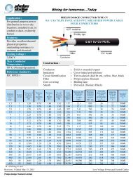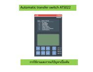
Tab 16.book - Piti Group
Tab 16.book - Piti Group
Tab 16.book - Piti Group

You also want an ePaper? Increase the reach of your titles
YUMPU automatically turns print PDFs into web optimized ePapers that Google loves.
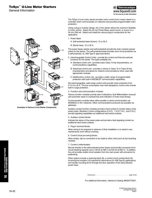
TeSys U-Line Motor StartersGeneral Informationwww.SquareD.comFor the most up-to-date information710The TeSys U-Line motor starter provides motor control from a basic starter to acontroller which communicates on networks and provides programmable motorprotection.Using a plug-in modular design, the U-line starter allows the maximum flexibilityin motor control. Select the 45 mm Power Base, panel mount, or mount on a35 mm DIN rail. Select and install the various plug-in components for theapplication.1. Power BaseA. Self-protected base (shown), 12 or 32 AB. Starter base, 12 or 32 AThe power bases (starter and self-protected) provide the main contacts (powerpoles) for the device. The self-protected base provides short circuit protection asa self-protected, UL 508 Type E approved device.922. Interchangeable Control Units—provide the control and thermal overloadfunctions for the starter. The types available are:A. Standard control unit—provides basic Class 10 trip characteristics, nocommunications capabilities.134B. Advanced control unit—provides a choice in Class 10 or Class 20 tripcharacteristics and allows for network communications when used withappropriate modules.C. Multifunction control unit—provides a wider range of programmableprotection with built-in MODBUS ® communication capabilities.Six interchangeable, wide-range control units provide motor protection from0.15 A to 32 A. The low consumption (low heat dissipation) control units includebuilt-in surge protection.Examples of Various U-Line Starter Components8563. Function and communication modulesVarious function modules provide alarm indications, fault differentiation (manualand automatic reset on overload trip) and indication of motor load (Amps).Communication modules allow either parallel or serial communication viaMODBUS or AS-i networks. Other communications protocols are possible viagateways.Auxiliary contact function modules provide a hard contact to monitor status of thepower poles. Modules in three configurations (2 N.O., 1 N.O/1 N.C., and 2 N.C)provide signaling capabilities as traditional hard-wired contacts.4. Auxiliary contact blocksIndicate the status of the power poles and provide a fault signaling contact astraditional hard-wired contacts.5. Plug-in terminal blocksAllow wiring to be prepared in advance of final installation or to assist in anymaintenance work without unwiring.6. Control circuit pre-wiring blocksAllow simple, clip-on connection to be made to other units (such as the reversingmodule).IEC STYLE CONTACTORSAND STARTERS167. Current Limiter/IsolatorMounts directly to the self-protected power bases and provides increased shortcircuit breaking capacity (up to 130 kA at 480 V and 65 kA at 600 V). In addition,the unit provides visible circuit isolation from the main power with provisions forpadlocking.Other options include a reversing block (8), a control circuit contact block (9),incoming line insulator (10) required for stand alone (UL 508 Type E) applications,and handle mounting kit for through-the-door operation of the self-protectedpower base.Dimensions. . . . . . . . . . . . . . . . . . . . . . . . . . . . . . . . . . . . . . . . . . . page 16-49For additional information, reference Catalog #8502CT0201.9/8/0316-42© 2003 Schneider ElectricAll Rights Reserved9/8/03