Tab 16.book - Piti Group
Tab 16.book - Piti Group
Tab 16.book - Piti Group

You also want an ePaper? Increase the reach of your titles
YUMPU automatically turns print PDFs into web optimized ePapers that Google loves.
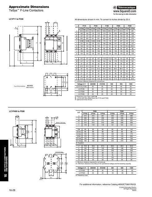
Approximate DimensionsTeSys F-Line Contactorswww.SquareD.comFor the most up-to-date informationLC1F11 to F330Ss1All dimensions shown in mm. To convert to inches divide by 25.4.a=cF115 F150 F185 F265 F330LC13-Pole 4-Pole 3-Pole 4-Pole 3-Pole 4-Pole 3-Pole 4-Pole 3-Pole 4-Polea 163.5 200.5 163.5 200.5 168.5 208.5 201.5 243.5 213 261b 162 162 170 170 174 174 203 203 206 206b1 137 137 137 137 137 137 145 145 145 145b2 265 265 301 301 305 305 370 370 375 375c 165b 165b 165b 165b 176 176 207 207 219 219bb2Mf 131 131 131 131 130 130 147 147 147 147G 106 143 106 143 111 151 142 190 154.5 202.5G1 80 80 80 80 80 80 96 96 96 96J 106 106 106 106 106 106 106 106 106 106J1 120 120 120 120 120 120 120 120 120 120=L 107 107 107 107 113.5 113.5 141 141 145 145cLQ P P Q1afM 147 147 150 150 154 154 178 178 181 181P 37 37 40 40 40 40 48 48 48 48Q 29.5 29.5 26.5 26 29 29 39 34 43 43Q1 60 60 57.5 55.5 59.5 59.5 66.5 66.5 74 74S 15 15 20 20 20 20 25 25 25 25Dual Dimensions:INCHESMillimetersJJ1b1 ==S1 27 27 34 34 34 34 38 38 44.5 44.5Y 44 44 44 44 44 44 38 38 38 38Z 13.5 13.5 13.5 13.5 13.5 13.5 21.5 21.5 20.5 20.5f = minimum distance required for coil removal.Voltage in V 220/380 415/440 500 660 1000LC1F115, F150 20 25 30 40 20LC1F185 20 25 30 40 30Z= G1 =GYLC1F265 20 25 40 50 40LC1F330 25 35 40 50 50a Protective cover Type LA9F70t.b + 6 mm with time delay block (for F115 and F150).c Optimal terminal shroudLC1F400 to F5002.2056=S 1.4938M10 X 30 dia.LC1F400F5002-Pole 3-Pole 4-Pole 2-Pole 3-Pole 4-Polea 213 213 261 233 233 288b 206 206 206 238 238 238b2 375 375 375 400 400 400c 213 213 213 226 226 226f 119 119 119 141 141 141IEC STYLE CONTACTORSAND STARTERSX1cL8.23209b=eb2Q P P Q1aMf8 X 8.5 dia.=4.7120==7.09180Gd 80 80 80 80 80 140G min. 66 66 66 66 66 66G max. 102 102 150 120 120 175G1d 170 170 170 170 170 230G1 min. 156 156 156 156 156 156G1 max. 192 192 240 210 210 265d SuppliedJ 19.5 19.5 67.5 39.5 39.5 34.5L 145 145 145 146 146 146M 181 181 181 208 208 208P 48 48 48 55 55 55Q 69 43 43 76 46 46Q1 96 74 74 102 77 77S 25 25 25 30 30 30f = Minimum distance required for coil removal.X1: Minimum clearance according to the operational voltage and the breaking capacity.Voltage in V 220/230 415/440 500 660 1000LC1F400 30 40 40 50 6016.9223.5GG1J=LC1F500 40 45 50 60 60e Protective cover.For additional information, reference Catalog #8502CT9901R5/03.16-289/8/03© 2003 Schneider ElectricAll Rights Reserved9/8/03