Tab 16.book - Piti Group
Tab 16.book - Piti Group
Tab 16.book - Piti Group

You also want an ePaper? Increase the reach of your titles
YUMPU automatically turns print PDFs into web optimized ePapers that Google loves.
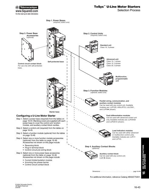
www.SquareD.comFor the most up-to-date informationTeSys U-Line Motor StartersSelection ProcessStep 1. Power Bases(required; select one)Step 5. Power BaseAccessories(optional)Step 2. Control Units(required; select one)Standard unitClass 10, 3-phaseControl circuit contact blockFor use only with self-protectedbase.Self-protected baseAdvanced unitClass 10, 1-phaseClass 10, 3-phaseClass 20, 3-phaseMultifunction,programmableunitStep 3. Function Modules(optional; select one)Starter baseConfiguring a U-Line Motor StarterStep 1. Select a power base (required) from the tables onpage 16-44. Blanking covers are supplied with eachpower base to cover the control unit, functionmodule, and auxiliary contact block cavities.Step 2. Select a control unit (required) from the tables onpage 16-45.Step 3. Select a function module (optional) from the tableson page 16-46.Step 4. Select one or more function module accessories(optional) from the table on page 16-46.Accessories not shown on this page include:• Reversing block• Plug-in terminal block• Control circuit pre-wiring blockStep 5. Select one or more power base accessories(optional) from the table on page 16-48.Accessories not shown on this page include:• Current limiter/isolation module• Incoming line phase barrier• Control circuit contact blockParallel wiring, communication, andauxiliary contact modulesCan be used with any control unit. Availablemodules are: LUFC00, ASILUFC5, LULC031,and LUFNt (shown).Step 4. Auxiliary Contact Blocks(optional)Fault differentiation modulesCan be used with advanced control unitonly. Available modules are: LUFDH20and LUFDA10 (shown).Load Indication modulesCan be used with either advancedor multifunction control units.Available modules are: LUFV1and LUFV2.Auxiliary contact blockCan be used with any control unit.LUA1t shown.IEC STYLE CONTACTORSAND STARTERSDimensions . . . . . . . . . . . . . . . . . . . . . . . . . . . . . . . . . . . . . . . . . . . page 16-49For additional information, reference Catalog #8502CT0201.166/20/04© 2004 Schneider ElectricAll Rights Reserved6/20/0416-43