nfcl, mangalore dap/npk plant feasibility study - Environmental ...
nfcl, mangalore dap/npk plant feasibility study - Environmental ...
nfcl, mangalore dap/npk plant feasibility study - Environmental ...

You also want an ePaper? Increase the reach of your titles
YUMPU automatically turns print PDFs into web optimized ePapers that Google loves.
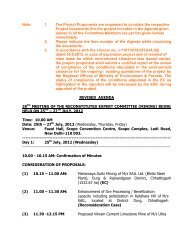
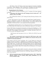
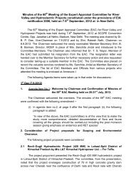
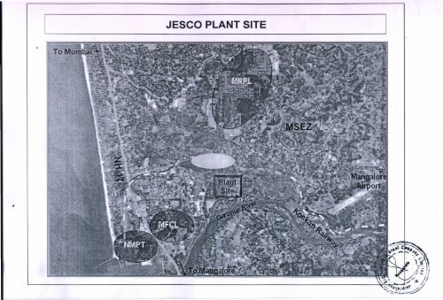
MANGALORE JESCO SITE MAP
MANGALORE JESCO SITE MAP (20 KMS RADIUS)
JESCO SITE-MANGALORE
1ANNEXURE-IVPROCESS DESCRIPTIONINTRODUCTIONThe <strong>plant</strong> consists of a two trains to produce NPKs / DAP granulated products,using Ammonia, MOP, Phosphoric Acid, Sulphuric Acid, Urea and Filler as rawmaterials.They will be produced with the granulation technology developed having PipeReactor installed into the granulator.NPK grades selected for the <strong>feasibility</strong> <strong>study</strong> are 10:26:26, 12:32:16, 20:20:0 withS 13 % by wt. However, various other NPK grades can be produced from the<strong>plant</strong> can be produced as 18:46:0 (DAP), 14:35:14, 4:30:10, 5:20:20, 8:24:8,8:24:16, 9:18:27, 10:25:25, 12:35:8, 14:14:14, 15:15:15, 16:16:8, 16:20:0,17:17:17, 20:10:15, 23:23:0, 28:28:0,…, ammonium sulphate, ammonium nitrateor urea based.Various sections are described below:Raw Material FeedsPhosphoric acid at 50-54% P2O5 strength is pumped from its storage day tankto the various destinations in the <strong>plant</strong>, namely the Pipe Reactor Tank, theGranulator Pre-Scrubber Tank, the Scrubber tank and occasionally to thePreneutralizer reactor.Liquid ammonia is pumped from storage to the liquid ammonia heater and fromhere to the Pipe Reactors, to the Granulator Ammoniation System and to theAmmonia Separator Vessel. Eventually liquid ammonia can also be sent to thePreneutralizer. These systems are described in detail at a later stage.
2ANNEXURE-IVSulphuric acid is used for pH and N/P control and it can be fed toPreneutralizer, to Granulator, to Granulator Pre-scrubber Tank, to the Scrubbertank and to the Tail Gas Scrubber.MOP, Urea, Filler and spillages (or off-spec product) is fed from their storagebuilding to the <strong>plant</strong> building by common conveyors. Once in the <strong>plant</strong> there isa common raw material Rotary Diverter, to feed the different solid raw materialto their correspondent bin. The quantity of raw materials added to thegranulation loop is controlled by the variable speed electronic feeders for Urea,Potash, Filler and Off-spec product respectivelySlurry preparation and GranulationDAP and NPKs without Urea are produced by Pipe Reactor(s), where 100% ofthe total ammonium phosphate / sulphate slurries will be generated. For DAPproduction two Pipe Reactors will be used simultaneously. For NPK productionone or two PRs will be used depending on the grade.A molar ratio N/P = 1.4-1.5 is reached at 135-145°C in Pipe Reactor for DAPproduction, as results of neutralizing a phosphoric acid of about 42-44% P2O5(including some sulphuric acid) with liquid ammonia.A molar ratio N/P = 1.4-1.5 is reached at 130-140°C in Pipe Reactor for NPKproduction, as results of neutralizing a phosphoric acid of about 40-42% P2O5(including some sulphuric acid) and liquid ammonia.NPK/NP with high content in Urea is produced using Preneutralizer Reactor,where 100% of the total ammonium phosphate / sulphate slurries will beprepared. In case of using mixed process, the slurry will be produced byPreneutralizer and Pipe Reactors.
3ANNEXURE-IVA molar ratio of N/P = 1.4-1.5 is reached at 115-125°C in Preneutralizer, asresults of neutralizing a phosphoric acid of about 33-40% P2O5 plus smallquantities of sulphuric acid and vapor ammonia (some exceptional occasionsliquid ammonia).PreneutralizerThe reaction between gas ammonia and phosphoric acid begins in thePreneutralizer. The Preneutralizer is equipped with an agitator to improveammonia absorption, to provide temperature and reaction uniformity, to reducefoaming and to maintain solids in suspension during short shutdowns.The Preneutralizer is specially designed to provide high freeboard, goodreactants mixing, low ammonia losses and low retention time, by making thelower section of a smaller diameter. This ensures maximum P2O5 solubility inthe product.Two pumps with independent piping systems are provided to constantly deliverthe required quantity of ammonium phosphate slurry from the Preneutralizer tothe Granulator. This arrangement permits washing or maintenance of onecomplete line while the other is in service, an important feature assuring a highon-stream operating factor. The Slurry Pumps are variable speed pumpscontrolled by variable frequency drives, thus eliminating the need for controlvalves in this difficult application.Acid fed to Preneutralizer is essentially constituted by the phosphoric andsulphuric acids used in the scrubbing system.Gases generated into the Preneutralizer are sucked up towards the FumesPre-Scrubber, to recover most of the evolved ammonia losses.
4ANNEXURE-IVPipe ReactorThe reaction between liquid ammonia and phosphoric acid takes place in thePipe Reactors, which are composed of a Mixing Head and a distribution Pipe,last one directly installed inside the granulator drum.For DAP and most of NPK grades production, both installed PRs will worksimultaneously. In some NPK grades only one PR will be enough to producethe necessary slurry.Acid fed to Pipe Reactor is constituted by the mixture of the fresh phosphoricacid fed to P.R. tank plus the mixture of phosphoric and sulphuric acids used inthe scrubbing system.Pipe Reactor is equipped with acid and ammonia flow controllers, acid beingfed by the variable speed Pipe Reactor Pumps.The use of liquid ammonia in the Pipe Reactor improves the control oftemperature in the granulator, which is very important especially in DAPproduction.Pipe Reactor residence time is only of few seconds, thus avoiding creation ofinsoluble P2O5, or formation or reaction compounds with a lot of bonded waterin their composition.An automatic and interlocked cleaning system has been also provided to flushthe Pipe Reactor with medium pressure steam in case of unexpected shutdownor scheduled flushing. In last case flushing will take less than one minute andwill be performed without stopping the rest of the <strong>plant</strong>.
5ANNEXURE-IVGranulationThe function of the granulation system is to transform the slurry and solid rawmaterials into a granular fertilizer product with the required composition andsize. Granulation occurs in the drum Granulator, where phosphate slurries aresprayed onto a bed of dry material, composed by the added solid raw materials(Urea, Potash, and Filler) plus the fines, crushed oversize and part of thecommercial product returned to granulator. Slurries are directly sprayed fromthe Pipe Reactor distribution Pipe, or by pumping from Pre-neutralizer pumps,in this last case sprayed using a distribution pipe with spray nozzles.The rolling action within the Granulator distributes the slurry evenly on thesurface of the granules, and produces a very uniform, hard, well-rounded,layered granule. The resultant thin film of slurry is easily dried after rolling andreaction with liquid ammonia.The Granulator is inclined towards the discharge end to facilitate transfer of thelarge recycle load. There are several emptying doors (4), at the granulator'sexit ring, to adjust bed depth to the optimum value, as well as to allowemptying granulator for maintenance / cleaning purposes.To complete the acid neutralization of the slurries to the required N/P ratio forDAP and NPK/NP grades, an Ammonia System is installed, to inject liquidammonia deep into the solids bed, promoting granules water evaporation.The Ammoniation System consists on rubber hoses supported from thegranulator's main beam. This system avoids the formation of lumps, provides ahomogeneous distribution of ammonia and reduces granulator powerconsumption, thanks to the almost absence of frictions caused by product solidbed while turning. Two independent distribution pipes with sprays are providedfor eventually feeding sulphuric acid and water inside granulator (over solidsbed).
6ANNEXURE-IVThe granulator is a carbon steel drum lined with rubber panels and equippedwith an apex scrapper, to minimize product build-up on the supporting beamand the rubber panels.It will be also equipped with a lumps kicker to prevent any lump from remaininginside the drum, disturbing the flow of solids and promoting other lumpsformation. Lumps kicker will make the lumps to jump to an attached grizzly,which will disintegrate them by the rotating action. Rest of product will leavethe granulator by passing through the grizzly bars.Solids leaving granulator, normally with moisture content around 2-3% will begravity fed to dryer, in order to achieve the final requested moisture of 1.0-1.5%.Gases developed into the granulator are sucked up towards the Fumes Pre-Scrubber 3, to recover most of the evolved dust and ammonia losses.DryingIn the rotary drum type Dryer, the solids are lifted and cascaded through a cocurrentflow of hot air from the Combustion Chamber. The dryer is designed formaximum efficiency and minimization of material build-up.The Combustion Chamber is FO fired. Air for combustion is supplied by theCombustion Air Fan. The Quench Air propelled by Fan is used to reduce thetemperature of the combustion gases up to a temperature adequate for thecombustion chamber.The temperature of the hot gases after dilution entering dryer is about 120-180°C (for NPKs with urea) and 130 -250°C (for DAP and NPKs without urea).
7ANNEXURE-IVControl of the firing rate can be done based on the dryer outlet gastemperature which is controlled at about 90-105°C, depending on the grade,product moisture content and the granulation temperature. In some cases firingrate on the dryer inlet gas temperature (specially recommended in NP productswith high Urea contents) is controlled with Dryer inlet gas temperature.The product at dryer discharge flows through the grizzly, consisting on a bargrizzly equipped with lumps lifter located on it. Broken lumps and small productwill flow through the grizzly bars, whereas harder lumps will be elevated andeventually fed by the elevator to the Lump Crusher, feeding chute. Oversizecrushed lumps will then join the rest of product in dryer exit belt conveyor,which feeds screen feed elevator.Dryer exit gas contains some dust that is removed in the dryer cyclones,collected in the cyclones hoppers and returned to the recycle.Dryer exit conveyor is equipped with a throughput weigher and a magneticseparator, installed to remove any metallic part that may damage oversizemills. From that belt conveyor, solids fall by gravity to the Exit Dryer Elevator.Screening and CrushingThe <strong>plant</strong> utilizes vibrating Oversize Process Screens. The Dryer Elevatorfeeds the Screens. Directly installed at the outlet branches of the ScreensSplitter there are two Screen Diverters, also with electrical motor actuator, thatwill be used for by-passing the correspondent screen and process crusher formaintenance and cleaning or when a partial (or total) emptying of the unit isrequired in a relatively short period of time.
8ANNEXURE-IVTo improve screen efficiency each screen has a dedicated vibrating feeder toevenly distribute the feed across its entire width.The Oversize Screens will separate from the on-size and fine product, theoversize fraction above 4 mm, which is crushed in four Oversize Mills. Feedingis accomplished by independent chutes from each screen. The suggested milltype is a double rotor chain mill, which provides and efficient crushing withsmall size dispersion on ground product.These mills directly discharge onto the Recycle Conveyor, through oversizedchutes. The product under 4 mm flows to the four single deck Undersizeprocess Screens, which separate the fines below 1 mm, sending them back torecycle.The on-size product from all four screens is collected in the Recycle RegulatorConveyors. These belt conveyors will adjust the required amount of productdesired for production. The extraction rate, controlled by the Recycle RegulatorBelt Weighers, will be fixed from DCS in Control Room and it will regulate beltsspeed and the amount of on size product going to final product treatmentsection. The operator should fix a rate on the weighers to extract from thegranulation loop only the required quantity of product to match the productionrate after passing through Cooler and Polishing Screen. Any excess of on-sizeproduct will not be extracted at that belt speed and will automatically overflowfrom the recycle regulating hoppers the recycle conveyor.The recycle conveyor will receive:Dust from all cyclonesFines from all undersize screensCrushed oversize from millsOverflow from recycle regulator conveyorsFines from polishing screen
9ANNEXURE-IVSpecial care should be devoted to the design of the Recycle Conveyor. Itshould operate at rather low speed, to avoid mechanical problems, and itscover should be dust tighten, for avoiding dust emission.The recycle conveyor discharges onto the Recycle Elevator that feeds all therecycle and solid raw materials to the granulator drum.Final Product ConditioningProduct on size material from the Recycle Regulator Conveyors is fed bygravity to the Cooler Drum. Cooler is counter current rotary type and thecooling air comes from Air Cooler Impulsion Fan. This air is previously chilledin the following way:- If PN is not used, the air is slightly chilled in the E.G. Air Chiller using the cold50 % Ethylene Glycol (EG) solution after heating the cold liquid ammonia.- If PN is used, the air is initially chilled in the same E.G. Air Chiller using thecold 50 % EG solution after heating the liquid ammonia and then is additionallychilled in the Cooler Ammonia Air Chiller which uses the cooling generated byammonia vaporization (ammonia vapor to be used in the PN).Rotary Cooler Fines Screw Conveyor is a small screw conveyor installed at theproduct feed end of rotary cooler for conveying towards the screen feedelevator the fines granules and gross particulates of dust entrained by thecounter-current air leaving the cooler that are collected in the cooler feed endhopper.
10ANNEXURE-IVTo prevent absorption of moisture by final product during the cooling processair have to be conditioned (chilled and dehumidified), mainly when ambient airis too wet, thus downstream Cooler Air Chiller is installed the Air Heater forreducing the air relative humidity above the product CRH. This is especiallyimportant when producing NPK/NP with high Urea content since they are veryhygroscopic compounds.DAP has a critical relative humidity CRH of about 75-85% at 30°C (lower athigher temperature) but Urea based NPK/NP has lower CRH, of around 45-50% , and they could retain moisture if the air feed to cooler has higher relativemoisture.The Cooler Air Chiller (and also the Quench Air Chiller) reduces the ambientair temperature by vaporizing the incoming liquid ammonia that is then fedPreneutralizer from ammonia separator. The chillers are followed by ademisters to prevent any condensed water may reach the Cooler (orCombustion Chamber in case of Quench air chiller).Dust coming out with the air leaving the Cooler is recovered in a battery ofcyclones and collected in their respective hoppers, from where it is fed back tothe recycle conveyor.About 55-65 % of the air leaving Cooler cyclones will be sent to the Cooler &Dedusting Scrubber for its washing, through the Cooler & Dedusting Exhaustfan, whereas the rest of this semi-clean warm air (35 - 45%) will be recycled tothe dryer as dilution air, through Air Cooler Recirculation Fan, improvingenergy efficiency and reducing at the same time the size of scrubbingequipment.Rotary Cooler discharges cooled product directly to Final Product Elevatorwhich lift it to the single desk Polishing Screen. Fines under 1 mm areseparated and returned back to recycle, whereas commercial size product
11ANNEXURE-IVbetween 1-4 mm falls by gravity to the Coater drum. Coating oil is added to theCoater Drum for caking control.Polishing Screen is equipped with a vibrating Feeder to improve the screeningefficiency to evenly distribute the feed across its whole width.Coating is particularly necessary when bulk storage during long periods of timeor ship exportation is envisaged, because the hygroscopic features of NPKgrades can promote caking, mostly when variations of air temperature andmoisture occur.Coating agent is normally an amine containing high viscosity oil or wax(paraffin), normally solid at ambient temperature and with a pour point ofaround 50°C.The coating oil is kept at around 70-80 °C in the Coating Oil Tank (using itssteam coil heater) and is fed to the coater drum by using the Coating OilDosing Pumps, through LP steam traced pipes and spray nozzles.After coating, product falls by gravity to the Final Product Belt Conveyor, whichwill send product to the final storage, outside B.L, via several conveyors onseries.
1ANNEXURE-IXENVIRONMENT CONTROL, SAFETY AND FIRE PROTECTION<strong>Environmental</strong> Control – GeneralPublic concern over environmental pollution is increasing at a geometric rate. Theconcern stems from an awareness of the threats to health and welfare from the wastesof our society. It leads inevitably to pressure on industry to reduce the discharge ofcontaminants into the air and public waterways.<strong>Environmental</strong> monitoring plans will be prepared for the project to ensure all activitiesof the project are operated in an environmentally safe manner. A brief note on thevarious environment impacts of the project and the remedial measures areenumerated hereinafter:During construction, the activities that might cause adverse effects to the area are- Site preparation- Site filling, flattening and reinforcement of the foundation- Transportation of materials and equipment to the site- Construction of infrastructure- Installation of equipment and support facilities for the <strong>plant</strong>These activities will be controlled primarily by the construction contractor(s) underagreement(s) with LSTK contractor / JESCO to follow the requirements to be satisfiedat site.During operations, the activities that have an adverse impact on the environment are- Transport and storage of feedstock and product- Operation of the production process- Gaseous waste and liquid waste.<strong>Environmental</strong> impacts of these activities will be controlled to a very low level satisfyingthe requirements of Karnataka Pollution Control Board (KPCB).<strong>Environmental</strong> protectionPrevention of Air Pollution
2ANNEXURE-IXEmissions from the <strong>plant</strong> are minimized with the application of nitrogen blanketing forstorage tanks, proper selection of pumps as per OSHA standard, proper selection ofgaskets, etc.Prevention of Water PollutionCooling tower will be installed for reducing the water requirement for cooling in thecomplex.As for process waste water, suitable Effluent treatment <strong>plant</strong> will be installed so as tocomply as per KPCB guide line. In order to prevent underground water pollution, theprocess area is paved with concrete & acid proof brick lining (wherever required) andoil, acid and rain water falling in the area is collected in a pond for further treatment.This waste water is discharged to the waste water treatment <strong>plant</strong> for treatment.Prevention of NoiseNoise level of working place will be controlled within the limit as specified in the KPCBstandard. In the case that some areas might not satisfy the said standard, suitablecountermeasures, e.g. addition of noise insulation, use of PPE etc., will be applied inorder to satisfy the said standard. Noise level at <strong>plant</strong> boundary fence will be controlledto satisfy noise criteria.HIGHLIGHTS OF EFFLUENT TREATMENT TECHNOLOGYFollowing are the main features of the modern scrubbing system technology.Scrubbing System Technology particularized for each case. This is a key point whendesigning <strong>plant</strong>s to operate with very soluble raw materials, since in those cases the waterto be recovered from the scrubbing system should be minimized.Technology BackgroundThe development of scrubbing Technology started long time ago and it has been carriedout in parallel with our granulation technologies, as the answer to a continuous demand for
3ANNEXURE-IXlower emissions, both to comply with the more stringent legislation and to recover most ofthe nutrients.Licensed PlantsThis technology has been successfully applied to DAP / NPK factories, achieving very lowemissions. The design is always a<strong>dap</strong>ted to the local legislation, to avoid at the same timehigh emissions and unnecessary expenses on scrubbing equipment.Ammonia RecoveryThis technology includes several washing stages to recover the ammonia, havingrecorded values as low as 10-50 ppm NH3.Dust / Particles RecoveryModern design consists of medium pressure drop scrubbing systems, which in conjunctionwith high efficiency separators, allow us to reach 10-50 ppm particles emission.Fluorine RecoveryModern technology includes several washing stages of lower pressure drop operating withwater, resulting in very low fluorine emissions.Stack gases OpacityReduction of stack opacity is based on the use of high pressure drop (HPD) scrubber,consisting on a sophisticated multi stages venturi, which provides recovery for the smallestsub micron particles and mists.Integration in the whole PlantModern scrubbing system engineering includes the <strong>plant</strong> mass & energy balance, statingthe suitable process parameters to assure that the fulfillment of scrubbing systemconditions does not interfere with the operation of reaction section.Nutrients recovery
4ANNEXURE-IXThanks to the use of scrubbing process, which recovers all the liquid into the reactionsystem, at the same time that emissions are fulfilled many nutrients will be recovered,greatly increasing <strong>plant</strong> efficiency.Zero Liquid EffluentsModern <strong>plant</strong>s are designed as zero liquid effluent, all liquids being recovered into thereaction section.Design PhilosophyTo achieve the objective the following design philosophy will be taken into the fireprotection facilities:(1) Fire protection facilities should be applied in accordance with National safetyregulations and codes/standards and with LSTK contractor safety standards.(2) Fire protection facilities should be applied to the hazards dependent on a hazardanalysis for a given installation. To determine the fire protection facilities, a fullreview of hazards and <strong>plant</strong> arrangement is required for the following:(a) Plot plans of process units and overall <strong>plant</strong> layout including siting of installationsuch as proximity to populated area or public ways, risk from adjacent facilities,topography (elevation and slope)(b) Characteristics of process, i.e., materials handled, operating pressure andtemperature and inventory.(c) Fire prevention measures including isolation valves, relieving system and/ordepressurizing system.(d) Materials of construction, including insulation and fireproofing design.(e) Use of equipment and building, e.g., vital instruments or non-spared equipment.(3) Fire extinguishing agent should be selected for the fluids handled in the <strong>plant</strong> fromeffective and economical view points.(4) Fire protection facilities are designed on the assumption that there will be only onemajor fire in a <strong>plant</strong> at a time. In this case a full surface tank dike fire will not betaken into the design.(5) The <strong>plant</strong> organization should be provided to line up a fire fighting organization tocontrol and/or extinguish fire.
5ANNEXURE-IXFire Water Storage & PumpsPlant SitePart of raw water storage tank is considered as Fire Water storage & adequate capacity isconsidered to store fire water for the complex. The fire water will be exclusively used forfirefighting activity sufficient for four hours fire water supply at the maximum fire waterdemand. The proposed fire pump system designed in accordance with NFPA 20 / TAC isadequate to support the facilities in the <strong>plant</strong>. Jockey Pump is employed to maintainheaders at pressure around 10 kg/cm2 g. 50% of total fire water demand is met by theEngine driven pumps and 50% shall be met by the Motor driven pumps. Fire pumps will bedesigned for automatic sequential start upon loss of fire water main pressure. All the FirePumps will be UL Listed and / or FM Approved for fire protection service.Water HydrantsWater hydrants will be distributed in the process <strong>plant</strong> and in open spaces for accessibility.In the process area and the atmospheric storage tank yard, the maximum distancebetween hydrants will be 60 m, whereas in the utility and building areas the distance is 90m.Water spray systemManually operated water spray system designed as per NFPA15 will be provided for thehighly flammable liquid storage tanks. The water spray system for the storage tanks andvessels will be designed for manual operation by employing the gate valves in safelocation. The water spray system will be designed for automatic operation by employingthe fire detection system. Piping materials used in the water spray system will be carbonsteel.Fire Alarm SystemElaborate Fire Alarm System has been considered in cost estimate.
1ANNEXURE-VStorage CapacitiesRaw material and finished product storage capacities have been worked outbased on past experiences, recommendation of port <strong>study</strong> carried out byJESCO.Liquid Raw Materials StoragesAmmonia : 2x10000 MTPhosphoric acid : 3x10000 MTSulphuric acid : 3x10000 MTSolid Raw materialsMOP, filler, Urea : 36000 MT (combined storage)products)Product StorageDAP / NPK : 30000MT (with equal partition for 3Utility StorageFuel oil : 500 m3Raw water tank : 5000 m3Treated water tank : 5000 m3(Fire water part of it)DM water : 300 m3Raw water reservoir : 150000 m3Bagging concept:In the bagging <strong>plant</strong> (situated at top of railway platforms), threehoppers for NPK / DAP are considered. Each hopper is connectedwith 2 lines of bagging machines.
2ANNEXURE-VTwo platforms (each15 meter wide & ~350 meter long) with threerailway lines along with the shade and bagging <strong>plant</strong> building areconsidered. Apart from other equipment for bagging and handlingconveyors for bulk/bags, a control room, an empty bag warehouse,supervisor rooms, maintenance room, store room and toilet areplanned on the bagging floor.Bagging <strong>plant</strong> shall have following capacities:NPK bagging @ 240 TPHBagging Plant Operation: 18 hours/day.Bagging Capacity (NPK) : 800 Bags/hr/line x 6 Lines x 18Hrs/day.86400 Bags/Day Equivalents to 4320TPD.Bag filling weightAccuracy of WeighingBag MOC & SizeSize - ~650 mm x 550 mm: 50 Kg per bag: ± 50 Grams/Sigma: PP woven with inside HDPE linerApart from railway loading one number truck loading facility isconsidered common for NPK.
1ANNEXURE-VISite DetailsJESCO intends to put two units of NPK units along with associated facilities. Bagging<strong>plant</strong>, bulk silo, raw material storages, offsite & utilities etc are part of associatedfacilities. This is a green field project & accordingly site infrastructure required, non <strong>plant</strong>buildings & necessary utilities are considered.JESCO has acquired land in Mangalore .With in the acquired land layout is developed.LocationThe site is situated at a distance of about 6 kilometers from New Mangalore Port andabout 10 Kilometers from the centre of the city. The site is about 8kilometers(roadDistance) north cast of the Mangalore airport. The National Highway No.17 (“NH-17”)and Baikampady industrial area bound the site on the western side, the Gurupur Riveron the South and Southern Railway embankment of Mangalore-Panambur railway lineon the north and east. The Thokur railway station, which is the southern take-off pointfor the Konkan Railways, lies north of the site within a radius of 2 Km from the Site. TheSouth-West boundary of the site is almost in parallel with Gurupur River. The North-Eastboundary of the site runs along with the Konkan railway track leaving just about 15 Mtrsto 20 Mtrs as a set back to the track.The site has been selected due to the reason that major raw materials are to be shippedwhich requires jetty facility and New Mangalore port trust is just 6.0 Kms from theproject site and is very much suitable for importing liquid &solid raw materials for thefertilizer project. The site has very good infrastructural facilities as it is located near to thenew International Airport (approx 8 KMs.), Seaport (approx. 6 KMs.), Railhead (approx. 2KMs) and Highway road (approx. 2 KMs). The site is very much suitable for setting upcomplex fertilizer <strong>plant</strong>.
2ANNEXURE-VICLIMATE DATAAir Temperature and HumidityMaximum dry bulb temp. 37.8 °CMinimum dry bulb temp. 16.7 °CDesign dry bulb temp 35 °CDesign min temperature 18 °CDesign relative humidity (max.) 100%Mechanical design basis equipmentAmbient temperature: 16.7°C min 40°C max.Design basis of air conditioning / ventilationOutdoor temperature: 35 °C 29 °C(Dry bulb)(wet bulb)Indoor temperature: 23 ± 1 °C(Note 2) 25±2 °C(Note 3)Relative humidity - indoor: 60 % (Note 2) 55 % (Note 3)Design basis of electrical equipment materialsMinMaxOutdoor temperature: 16.7°C 40 °CSoil temp.(considered same as max. ambient) 40 °C 40 °CIndoor temperature: 11.1 °C 40 °CRelative humidity 100 %Design basis of cooling towersWet bulb temperature 29 °CDesign dry bulb temp 35 °C
3ANNEXURE-VINote 1: Design relative humidity : 60% @ 35°C for processdesign of air desaturation unit of NPK<strong>plant</strong>Note 2: For <strong>plant</strong> control roomNote 3: For split A.C., extended UPS room and modified transfer towerRainfallDesign rainfall : Annual rainfall 5831 mmWindWind direction :Prevailing direction : Owner to provide.Wind Pressures and Analysis : As per IS-875 - Part-III) –1987Basic wind speed : 39 m / sRisk coefficient K1 : 1.0 as per Table 1.Terrain height / structure size : As per Table 2.Factor K2 :- Category (Terrain) : Category 2Class : As per Cl. 5.3.2.2 BTopography factor : K3 = 1Pressure coefficient on :Roof : Determined in each caseWind ward side : as per Clause 6 of IS-875Lee ward side :Based on above K1, K2 and K3 factors, the basic wind pressure fordifferent class of structures will be calculated.Ht. In (m) Designwind pressurein KN/m²Class ‘A’Designwind pressurein KN/m²Class ‘B’Designwind pressurein KN/m²Class ‘C’10 0.9 0.864 0.78
4ANNEXURE-VI15 0.99 0.936 0.84620 1.026 0.99 0.930 1.128 0.966 0.97250 1.23 1.188 1.092100 1.386 1.338 1.23Note: Linear interpolation for intermediate heights shall befollowed.Barometric PressureMax. barometric pressure : 1.0135 bar aMin. barometric pressure : 1.0011 bar aDesign barometric pressure : 1.007 bar aSeismic FactorSeismic Zone : Zone IIICategory & importance factor considered : As per IS 1893 : Part 4 :2005:Annex APLANT Site ConditionsPLANT AREASite filling up to 5.5meters above MSL.Soil Exploration DataSoil conditions: As per soil report by the JESCO.Net safe Bearing pressure : 3 to 5 mt/m² at 2.0 m depth withFilling of 4.0 m for 25mm settlement.Ground water level : Almost at the existing ground levelFoundation depth (below base line) :of @ 31m.Pile foundation with a length
5ANNEXURE-VIPLANT LayoutBasic Layout PlanWidth of RoadsMain roads : 12 meters wideSecondary roads : 6 meters wideAccess ways : 3-5 meters
1ANNEXURE-VIITerms of Reference (TOR)The terms of reference for EIRA Studies for the proposed (DAP / NPK) Fertilizer ManufacturingPlant at Mangalore are as underI. <strong>Environmental</strong> Impact AssessmentI.1.0 IntroductionDAP / NPK is an important fertilizer without which Indian agriculture cannot survive and Governmentof India is bound to support this industry through conducive policies/subsidies. All southern states ofIndia namely Karnataka, Tamilnadu, Kerala and Andhra Pradesh have enough demand for DAP/NPKfertilizers, SSP, which is a poor farmer’s fertilizer (Price-wise), is an option to optimize the use ofPhosphatic fertilizers. It also helps to treat sulphur deficiency in soils (40% Indian soil are sulphurdeficient) as well for further enhancement of yields at the least cost. Various crops which requiremore of sulphur and phosphate are oilseeds, pulses, sugarcane, fruits and vegetables, tea etc, SSP isan essential fertilizer. GOI is encouraging use of SSP by giving subsidy.It is proposed to set up Complex (DAP / NPK) Fertilizer Manufacturing Plant at Mangalore. It isproposed to prepare <strong>Environmental</strong> Impact Assessment Report based on one season and three seasonsenvironmental quality data and Risk Assessment (RA) report with the following scope and detailedwork plan. The scope of work presented here is subjected to revision based on scrutiny and reviewof the Expert Appraisal Committee (EAC) members of Ministry of Environment and Forests (MoEF) andto decide upon the comprehensive terms of reference (ToR) for the preparation of EIA and RA inrespect of the proposed activity.I.2.0 Objectives of the StudyThe <strong>Environmental</strong> Impact Assessment (EIA) <strong>study</strong> will based on one season monitoring data followedby submission of comprehensive (three season) report. The EIA studies will be carried out as per theguidelines and requirements of Ministry of Environment and Forest, Central Pollution Control Boardand the State Pollution Control Board.
2ANNEXURE-VIIThe studies shall cover the following:• Assessment of present status of major components of environment viz. air, noise, water,land, biological and socio-economic components of environment including noise andparameters of human interest within 10 km radial distance from the <strong>plant</strong> site.• Identification of potential impacts on various environmental components due to existingand proposed activities envisaged during construction and operation phases of theproposed <strong>plant</strong>.• Prediction and evaluation of significant impacts of existing and proposed activities onmajor environmental components through appropriate mathematical / simulation models.• Preparation of appropriate <strong>Environmental</strong> Management Plan (EMP) incorporating controltechnologies that need to be adopted for mitigation of anticipated potential adverseimpacts.• Delineation of the post-project environmental quality monitoring program to be pursuedby M/s.NFCL.• Assistance in presentation for public hearing with the help of State Pollution ControlBoard and incorporation of minutes of the meeting with compliance in the final report,ToR approval filling up of Form – I and <strong>Environmental</strong> Clearance before the AppraisalCommittee, MoEF, New Delhi.I.3.0 Details of <strong>study</strong>I.3.1 Air Environment• Establish existing status of ambient air quality with respect to parameters viz. PM 10, PM 2.5,NOx, SO 2, NH 3 etc. within 10km radial area around the proposed <strong>plant</strong> site as per the MoEFNotification 2009 for one and three seasons.• Collection of meteorological data such as wind speed, wind direction, cloud cover andtemperature concomitant to ambient air quality monitoring for one and three seasons.• Estimation of stack emissions from the existing and proposed <strong>plant</strong>s based on processdetails.
3• Identification, quantification and prediction of impacts due to potential emissions.ANNEXURE-VII• Prediction of cumulative Ground Level Concentrations (GLCs) of air pollutants throughappropriate air quality models incorporating the requirements specified in the publicationof Central Pollution Control Board “Assessment of Impact to Air Environment: Guidelinesfor conducting Air Quality Modeling.• Evaluation of the adequacy of proposed pollution control facilities.I.3.2 Noise Environment• Collection of baseline data on the ambient noise levels at the <strong>plant</strong> site traffic area(Roads / Rail) and in nearby residential areas, industrial units and silence zone.• Prediction and evaluation of impacts due to increase in noise levels on the surroundingenvironment.• Suggestions on mitigation measures required to reduce the excess noise levels.I.3.3 Water Environment• Study of water resources with respect to quantity and quality within the <strong>study</strong> area. Thedata will be collected for one and three seasons.• Assessment of marine water quality within the <strong>study</strong> area.• Assessment of water requirement for the existing and proposed <strong>plant</strong>.• Assessment of the quality and quantity of waste water to be generated from variousproduction process/operations.• Prediction of impacts on water quality of receiving water body due to discharge of treatedwaste water employing appropriate mathematical/simulation models.• Evaluation of adequacy of the existing and proposed treatment systems, andsuggestions/modifications, if required.
4ANNEXURE-VII• Ground water monitoring at 6 locations and also near solid/hazardous waste dump/zone ifany.• Assessment of <strong>feasibility</strong> of water recycle and reuse in process or green belt development.I.3.4 Land Environment• Land use/land cover through remote sensing techniques using satellite imagery within the10 km radius area from the proposed facilities.• Delineation of present land use pattern with respect to agriculture and forestry.• Collection of soil samples from representative sites and detailed characterization of soils.• Detailed studies on sources, characteristics, treatment and disposal requirements forsolid/hazardous wastes from existing <strong>plant</strong> and that likely to be generated from theproposed processes.• Estimation of anticipated impacts, if any, on land use pattern with respect to agricultureand forestry.• Study of specific sensitive locations like national parks, wildlife habitats, archaeologicalstructures etc. within the impact zone.I.3.5 Biological Environment• Collection of existing information on flora and fauna in the <strong>study</strong> region.• Assessment of likely damage to flora and fauna due to effluents/emissions from theproposed <strong>plant</strong>.• Assessment of species diversity, density, abundance etc. within the <strong>study</strong> investigation.• Collection of published data on vegetation pattern and conduct field investigations.• Identification of existing endangered and dominant <strong>plant</strong> species in the <strong>study</strong> region.I.3.6 Socio-economic Environment
5ANNEXURE-VII• Collection of demographic data pertaining to human settlement, male to female ratio,age distribution pattern, income, health, endemic diseases, mortality, occupation andemployment pattern in the <strong>study</strong> region.• Collection of information related to prominent endemic diseases (flourosis, malaria,filarial, malnutrition) including mortality rates in the <strong>study</strong> region.• Projection of anticipated changes with respect to above parameters and delineation ofguidelines to minimize the adverse impacts.• Assessment of aesthetic impairment.• Assessment of socio-economic benefits to the community and environment due to existingand proposed projects.I.4.0 <strong>Environmental</strong> Management Plan<strong>Environmental</strong> Management Plan (EMP) will be drawn after identifying, predicting and evaluation thesignificant impacts on each component of the environment with a view to maximi8zing the benefitsfrom proposed <strong>plant</strong>. Post-project <strong>Environmental</strong> Monitoring (PPEM) for various environmentalcomponents will be delineated. The following measures will also be included in EMP.• Recommended mitigation measures required to address environmental concerns such as,clearing and timber salvage, wildlife and habitat protection, cultural and archaeologicalsites protection, terrain stabilization, maintaining fresh water horizons, debris disposaland conservation of natural drainage and water flow.• Assess additional infrastructures for treatment of flue gases, wastewater, sewage, andsolid/hazardous waste.• Provide a comprehensive and detailed plan covering environmental and social variables tobe monitored, the location and timing of sampling and the use to be made of monitoringdata to ensure compliance with the applicable environmental rules/regulationsthroughout the life of the project.
6ANNEXURE-VIIII. Risk AssessmentII.1.0 Details of <strong>study</strong>Rapid Risk Assessment <strong>study</strong>ing including hazard identification based on maximum credible accident(MCA) analysis, hazard assessment and evaluation employing techniques of consequence andvulnerability analysis and delineation of Disaster Management Plan (DMP) and EmergencyPreparedness Plan (EPP) for handling and storage in Mangalore Site and pipeline from jetty to <strong>plant</strong>.II.2.0 Objectives of StudyThe objectives of <strong>study</strong> are:• Hazard identification with recourse to hazard indices, inventory analysis.• Maximum credible accident analysis to identify potential hazardous scenarios for releaseof flammable materials from storage facilities.• Consequence analysis of failure cases identified with respect to heat radiation andpressure wave due to release of flammable materials.• Assessment of risk on the basis of above evaluation against risk acceptability criteriarelevant to the situation.• Preparation of disaster management plan.• Suggestions on risk mitigation measures and emergency preparedness plan.II.3.0 Details of Work PlanII.3.1 Hazard Identification• Collection of relevant information on hazardous materials stores and handled.• Study of vulnerable operations from various process units and storage section of hazardousmaterials using maximum credible accident (MCA) analysis.This <strong>study</strong> will lead to identification of hazard prone operations/sections /units and calculation ofdamage distances based on probable accident scenarios.II.3.2 Hazard Assessment and Evaluation
7ANNEXURE-VIIHazard prone operations / units would be critically examined with an accent on quantification ofhazard and its evaluation. The following techniques shall be used for quantification:• Consequence analysis and vulnerability analysis.• Individual and societal risks and plotting of risk contours.II.3.3 Disaster Management Plant (DMP)Safety checklist and risk mitigation measures would form integral part of DMP.II.3.4 Emergency Preparedness Plan (EPP)EPP would deal with onsite and offsite emergency plans.
1ANNEXURE-VIIIDust and Fumes CollectionAll process equipment in the <strong>plant</strong> operates under a small negative pressure in order toprevent the escape of unreacted ammonia, other gases and dust from the process.Air containing ammonia, water vapor and dust from the Preneutralizer and PipeReactor / Granulator is vented to the Granulator Fumes Pre-Scrubber, where ammoniaand a major portion of the dust are removed by reacting with the phosphoric acidcontained in the circulating scrubber solution.From the Pre-Scrubber the gas flows to the Granulator Scrubber, where most of theremaining ammonia and dust are removed. Air leaving this Scrubber is sucked by theGranulator Exhaust Fan and feeds the double step Tail Gas Scrubber, to recoverfluorine evolved during phosacid washing and to complete ammonia and dustrecovery.Gas containing ammonia and dust from the Dryer, flows to the Dryer Cyclones, toremove major portion of the dust, which is returned to the Recycle conveyor. Gasesfrom the cyclones flow to the Dryer Scrubber, sucked by the Dryer Exhaust Fanlocated downstream the scrubber, and from there to the Final Tail Gas Scrubber forfurther ammonia and dust removal and to recover fluorine evolved.Air containing dust from solids handling equipment (conveyors, elevators, screens,etc.) is vented into the Dedusting Cyclones, where most of the dust is removed. Airfrom the cyclones flows to the Cooler & Dedusting Scrubber, to be jointly washed withthe gases coming from Cooler Cyclones.Air from Rotary Cooler, containing some lower quantity of dust, is cycloned to removemost of the dust. Approximately 35-45% of that gas stream is recycled to the dryer,
2ANNEXURE-VIIIwhereas the other 55-65 % is sent by the above mentioned Cooler & DedustingScrubber to be jointly washed with the gases coming from Dedusting Cyclones.ScrubbingA powerful scrubbing system has been designed not only to remove effluents from gasstreams, but also to recover the nutrients, thus increasing <strong>plant</strong> efficiency.The scrubbing system for this <strong>plant</strong> consists of three washing steps:1st step: Granulator Pre-Scrubber, a low pressure venturi with cyclonic tower scrubberthat includes also a Duct Scrubber.2nd step: Granulator Scrubber, Dryer Scrubber and Cooler & Dedusting Scrubber, allof them Venturi Scrubber with Cyclonic separator tower.3rd step: Tail Gas Scrubber — two step scrubber with a Duct washing Scrubber and aPacked Tower Scrubber.EXPECTED EMMISSIONSGaseous EmissionsThe following maximum limits shall be used as a basis for ambient air qualitystandards, measured at measuring points on stack. Following limits are stringentwith respect to CPCB norms.NPK / DAPStack air outlet : 430000 m3/hr (expected) from each unit of two <strong>plant</strong>sParticulates : ≤ 75 mg/Nm 3Fluorine : ≤ 15 mg/Am³Ammonia : ≤ 75 mg/Nm 3Fugitive Air EmissionFugitive emission is expected from the various sources of the Plant. e.g,
3ANNEXURE-VIII- In-line/open valves- Flanges- Pressure relief devices- Pump seals- Compressor seals- Sampling connections- Field instruments- Open vents of pitsThese fugitive emissions will be controlled by suitable application of low emissionvalves, pump seals & scrubbers etc. These Plants will be designed, constructedand operated satisfying the KPCB standard regulations & guidelines.Liquid Effluents:There are no liquid effluents from the NPK / DAP <strong>plant</strong>s during normal operationexcluding leakages, cleaning. There is a sump tank in respective units wherespillages can be collected and subsequently reused in respective process units.Liquid effluents from other <strong>plant</strong>s are neutralized in common neutralization pit &pumped up to <strong>plant</strong> B.L.Solid wastesAll solid waste and spillages will be collected and re-introduced in the <strong>plant</strong>.Noise EmissionNoise emission is expected from the various sources like- Compressors- Blowers / fans- Centrifugal pumps- Control valves, etc.Noise emission from these sources will be controlled as follows.
4ANNEXURE-VIIINoise Level inside PremisesNoise level of working place will be controlled within the limit as specified in thestandard of KPCB, Karnataka. In the case that some areas might not satisfy thesaid standard, suitable counter measures, e.g. addition of noise insulation, etc.,shall be applied in order to satisfy the said standard.Noise Level at Boundary FenceNoise level at Boundary Fence will be controlled to satisfy noise criteria in KPCB,Karnataka, which is less than 75 dBA. In the case that the noise level might exceedthe said noise criteria, suitable counter measures as stated above, shall be appliedin order to satisfy the said noise criteria.
ANNEXURE-XFEASIBILITY REPORTONNPK PLANTS WITH ASSOCIATED FACILITIESATMANGALOREJAIPRAKASH ENGINEERING & STEEL COMPANYAUGUST 20121
INDEXPART ICHAPTER 1CHAPTER 2CHAPTER 3CHAPTER 4CHAPTER 5CHAPTER 6CHAPTER 7PROJECT AT A GLANCEEXECUTIVE SUMMARYINTRODUCTIONTECHNOLOGY COMPARISIONSITE DETAILSPLANT DESCRIPTION AND CONSUMPTIONENVIRONMENT CONTROL, SAFETY AND FIRE PROTECTIONPART IIFINANCIAL ANALYSISCHAPTER 8CHAPTER 9FINANCIAL INDICES & ANALYSISCONCLUSION2
PART - I3
CHAPTER – 1PROJECT AT A GLANCE4
1.1 IntroductionOwnerConsultantPlant LocationProducts: Jaiprakash Engineering & steel company (JESCO)(A Nagarjuna Group company): Uhde India Private Limited, Mumbai (UIPL): Mangalore, Karnataka, India: NPK / DAP1.2 Design Capacity : NPK / DAP based on 2X1650 MTPD DAP (18:46:0)(Based on 22 hours of operation in a day)1.3 Design On-Stream Time : 320 days per annum for NPK(Excluding loss time for cleaning)1.4 Turn Down Ratio : 50 % of design capacity for each <strong>plant</strong>1.5 Feasibility <strong>study</strong>:Feasibility <strong>study</strong> for this <strong>plant</strong> has been carried out considering the production offollowing grades & their respective capacities per annum:270000 MTPA of NPK (10:26:26)270000 MTPA of NPK (12:32:16)360000 MTPA of NPK (20:20:0) with S 13 % by wt(All above capacities are based on 22 hours of operation in a day)5
CHAPTER – 2EXECUTIVE SUMMARY6
EXECUTIVE SUMMARYFeasibility <strong>study</strong> for proposed NPK <strong>plant</strong> and associated facilities Project of M/sJAIPRAKASH ENGINEERING & STEEL COMPANY (JESCO), a Nagarjuna Group Company,.is to be located at Mangalore, Karnataka State was carried out.JESCO intends to put two units of NPK units along with associated facilities. Bagging <strong>plant</strong>,bulk silo, raw material storages, offsite & utilities etc are part of associated facilities. This is agreen field project & accordingly site infrastructure required, non <strong>plant</strong> buildings & necessaryutilities are considered.JESCO has acquired land in Mangalore .With in the acquired land layout is developed. Thesame was attached as attachment. Accordingly, the project cost is worked out as indicatedbelow.Total investment is worked out as Rs. 777.1 crores excluding start-up, pre-operative expensesand margin money and Rs. 984.2 crores with start-up, pre-operative expenses and marginmoney.7
CHAPTER – 3INTRODUCTION8
INTRODUCTIONM/s Jaiprakash engineering & steel company (JESCO) is a Nagarjuna Group Company.Nagarjuna Group is a US $ 3 Billion asset-based group.Nagarjuna is recognized as one of the most successful integrated agricultural inputbrands in India. They are ranked amongst the largest fertilizer companies in India (witha market share of 10% in Urea and a market share of 30% in specialty fertilizers)Nagarjuna Group is in the business of Urea, DAP, Water soluble fertilizers,Micronutrients like Zinc Sulphate etc. The above products are well established in themarket with the brand name of NFCL with significant contribution.Phosphatic Fertilizers (Complex) is an important area of fertilizers segment. India is theThird largest producer and Second largest user of Phosphatic fertilizers and has one ofthe largest areas under Irrigation. Complex Fertilizers includes DAP (Di AmmoniumPhosphate) and NPK Fertilizers.There is huge demand of Phosphatic fertilizers in the country. India has produced, 545.6thousand Tonnes DAP against the production capacity of 7022 thousand Tonnes during2010-11 and imported 7,410.92 thousand Tonnes. In India, DAP is the major productcontributing 62.7% of the total phosphate consumption. The estimated total demandsupply gap by 2015-2016 would be 11.12 Million MT of DAP.India is almost fully depending on imports of Phosphatic fertilizers or the intermediatesrequired for production of NPK Products like Phosphoric acid, Rock Phosphate, Murateof Potash, Ammonia etc.Nagarjuna group, a major industrial house in Southern India, as a business developmentstrategy, is exploring for development of fertilizer projects in India.In this regard, DAP/NPK have been identified as the prospective fertilizer projects byJESCO. The outputs DAP/NPK from the fertilizer <strong>plant</strong>s will be transported to differentparts of India for Marketing.By entering the business of Phosphatic fertilizers, Nagarjuna Group shall become one ofthe biggest fertilizer Industries in India to have both Nitrogenous and Phosphaticfertilizers under single entity. Installing production facilities for DAP/NPK shall facilitateNagarjuna Group to become complete <strong>plant</strong> nutrition provider in India. This project shallalso help in meeting partly India’s requirement of DAP/NPK.JESCO is proposed to set up of Complex (DAP /NPK) Fertilizer Manufacturing Plant atMangalore under the name of Jaiprakash Fertilizer & Chemical Complex (JFCC). A DAP9
NPK Fertilizer Manufacturing Plant of 0.90Million MT/Year NPK Complex Fertilizer withfollowing breakup of individual NPK grade.270000 MTPA of NPK (10:26:26)270000 MTPA of NPK (12:32:16)360000 MTPA of NPK (20:20:0) with S 13 % by wtTo meet this requirement two units of DAP <strong>plant</strong> each having capacity of 1650 TPD areselected (Based on 22 hours operation per day). Product specifications are mentionedbelow:Product SpecificationsNPK grades:Grade : 20-20-0Ammoniacal N : min. 18% (w/w) – As per FCOTotal N in form of Urea : max 2% (w/w) – As per FCOTotal nitrogen : min. 20% (w/w) – As per FCONeutral Ammonium Citrate SolublePhosphate (as P 2 O 5 ) : min. 20% (w/w) – Asper FCOWater Soluble Phosphates (as P2O5) : min. 17% (w/w) – As per FCOMoisture Content : max. 1.0% (w/w) – As per FCOSulphur (as S) : min. 13% (w/w) – As per FCOParticle Size : 1 to 4 mm (IS sieve) 90%w/w min< 1 mm (IS sieve) 5% w/w maxGrade : 12-32-16Total N : min. 12% (w/w) – As per FCOAmmoniacal N : min. 9% (w/w) – As per FCOTotal N in form of Urea : max 3% (w/w) – As per FCOWater Soluble Phosphates (as P2O5) : min. 16% (w/w) – As per FCOWater Soluble Potash (as K2O) : min. 27.2% (w/w) – As per FCONeutral Ammonium Citrate SolublePhosphate (as P2O5) : min. 32% (w/w) – As per FCOMoisture Content : max. 1.0% (w/w) – As per FCOParticle Size : 1 to 4 mm (IS sieve) 90%w/w min< 1 mm (IS sieve) 5% w/w maxGrade : 10-26-26Total N : min. 10% (w/w) – As per FCOAmmoniacal N : min. 7% (w/w) – As perFCO10
Total N in form of Urea : max 3% (w/w) – As per FCOWater Soluble Phosphates (as P2O5) : min. 22.1% (w/w) – As per FCOWater Soluble Potash (as K2O) : min. 26% (w/w) – As per FCONeutral Ammonium Citrate SolublePhosphate (as P2O5) : min. 26% (w/w) – As per FCOMoisture Content : max. 1.0% (w/w) – As per FCOParticle Size : 1 to 4 mm (IS sieve) 90%w/w min< 1 mm (IS sieve) 5% w/w maxGrade : 18-46-0 (DAP)Total N : min. 18% (w/w) – As per FCOAmmoniacal N : min. 15.5% (w/w) – As per FCOTotal N in the form of Urea : max. 2.5% (w/w) – Asper FCOWater Soluble Phosphates (as P2O5) : min. 41% (w/w) – As per FCONeutral Ammonium Citrate SolublePhosphate (as P2O5) : min. 46% (w/w) – As per FCOMoisture Content : max. 1.5% (w/w) – As per FCOParticle Size : 1 to 4 mm (IS sieve) 90%w/w min< 1 mm (IS sieve) 5% w/w maxTolerance limits for Nitrogen and Phosphate contents in the above products shall be 0.5units.Feed Stock (Raw material)AmmoniaState : LiquidTemperature : at storage tank conditionsPressure : at storage tank conditionsChemical AnalysisNH3 (min). : 99.5 +/- 0.5 wt. %Water (max). : 0.5 Wt. %Oil : 10 ppm Max.Sulphuric AcidState : liquidTemperature : ambientPressure : 3 - 4 kg/cm 2 gChemical AnalysisH2SO4 min. : 98 +/- 1.0 Wt. %Water max. : 3 Wt. %Impurities : Nil11
Phosphoric AcidP205 : 50 to 54% WtH2S04 (As S04) : 4.5% max.CaO : 0.6% Wt max.Al 2 0 3 : 0.1 to 2.0% Wt,Fe203 : 0.2 to 1.9% WtR203 (Al203 + Fe203) : 3.75% MaximumF : 1.8% Wt max.MgO : 1.6% Wt max.Cl : 250 ppmSuspended Solids : 1.5 to 2.5% WtSp. Gr. : 1.63 to 1.73Pressure : 3.0 Kg/cm2gTemperature : AmbientPotash (MOP)K2O : 60% Wt minMoisture : 0.5 % Wt maxParticle size : Not less than 65% of material shall passthrough 1.7 mm IS sieve. Not less than 65% of material shall be retained on 0.25mm IS sieve.Organic matter : 200 ppm maxTemperature : AmbientPhysical state : Free flowing without lumpsFillerType : Bentonite / ClaySize : 0.17 mm to 1 mm 90% minMoisture : 0.5% Max.Bulk density : 720 kg/m3Conditions : Free flow and without lumpTemperature : Ambient.Screen Analysis: + 16 mm - 60 mm 1 % Max. 40 %Max.Moisture7 % Max.Acid insoluble as silica (SiO 2 ) ** 40 - 80 %Iron as Fe2O3 **25 % Max.Aluminum as Al 2 O 3 **20 % Max.Calcium as Cao ** 1 - 2 %Magnesium as MgO **4 % Max.Carbonate and bi-carbonate as CaCO3 **9 % Max.Na2O ** 2 - 4 %K2O ** 0 - 1 %** On dry basis12
Coating OilType : Aminated waxTemperature : 60 °C (max)De-foamerState : liquidType : fatty acid oilDesign ScopeEntire <strong>plant</strong> is divided in to several sections as given belowDescription of UNIT/ SectionTrain A NPK Plant – Granulation SectionTrain A NPK Plant – Drying and Cooling SectionTrain A NPK Plant – Raw Material HandlingTrain A NPK Plant – Air dehumidificationTrain B NPK Plant – Granulation SectionTrain B NPK Plant – Drying and Cooling SectionTrain B NPK Plant – Raw Material HandlingTrain B NPK Plant – Air dehumidificationNPK Plant Raw material storage & Handling (common for NPK trainA / train B)NPK <strong>plant</strong> Bulk silo, Screen house and Product handling (commonfor NPK train A / train B)Bagging <strong>plant</strong> (common for NPK train A / train B)Raw water Pre-treatment & process water unitCooling Tower AreaPlant & Instrument Air systemAuxiliary BoilerEmergency Diesel generatorFuel oil storageChemical StorageRaw water & Fire Water Storage tanks & DM Water UnitAmmonia storage & refrigeration systemPhosphoric acid storage13
Sulphuric Acid StorageCentral Control Room & LaboratoryOutdoor switchyard and main 11kV substationO&U Substation cum MCC RoomNPK Substation cum MCC Room (common for NPK train A/ train B)Bagging Plant-MCC roomEmpty Bag Storage AreaNeutralization & Waste Water PitSpace for Future train CSpace for future captive power <strong>plant</strong>Effluent Treatment PlantWater Storage ReservoirSecurityAdministrative BuildingCar ParkingWeigh bridge CabinFire StationFirst Aid RoomCanteenTruck ParkingWorkshopWarehouseLiquid AmmoniaLiquid ammonia will be unloaded from ship via trolley mounted unloading arm atport & transferred via ammonia unloading line up to ammonia storage tanks (2 x10000 MT) located inside <strong>plant</strong> B.L.. Ammonia transfer pumps are provided tosupply liquid ammonia from each storage tank up to the consumers.Sulphuric AcidSulphuric acid pipeline from port to the Sulphuric acid storage tanks (3 x 10000MT) located in <strong>plant</strong> B.L. considered. Sulphuric acid transfer pumps are providedto supply Sulphuric acid from each storage tank up to the consumers.14
FO FuelFO is considered as fuel & shall be made available at storage tank in <strong>plant</strong> B.L.Net calorific value minimum 9780 kcal/kg is considered.50-54% Phosphoric acidPhosphoric acid will be unloaded from ship via trolley mounted unloading arm atport & transferred via phosphoric acid unloading line up to phosphoric acidstorage tanks (3 x 10000 MT) located inside <strong>plant</strong> B.L.. Phosphoric acid transferpumps are provided to supply Phosphoric acid from each storage tank up to theconsumers.Filler / UreaFiller / Urea shall be made available by trucks in storage area (common for MOP,filler & urea) and shall be charged to conveyor by pay loaders.MOPMOP shall be made available by trucks in storage area of total capacity 36000MT (common for MOP, filler & urea with individual capacities of 30000 MT,2000MT & 4000MT respectively) and shall be charged to conveyor by payloaders.DefoamerDefoamer shall be supplied in drums at the inlet nozzle of defoamer tank.Coating OilCoating oil shall be supplied in drums at the inlet nozzle of coating oil tank.Ethylene GlycolEthylene Glycol shall be supplied in drums at the inlet nozzle of Ethylene glycolstorage tank inside DAP / NPK Plant (ethylene glycol must be pre-mixed with theinhibitor).Raw water / Fire waterRaw water is provided for the <strong>plant</strong>. Further storage, processing will be doneconsidering the quality of raw water received.Fire water will be provided internally from raw water storage area with necessarypiping and other systems to take care of requirement of fire fighting system (as perTAC) for entire <strong>plant</strong>.Empty BagsTo be stored at empty bag storage area in bagging <strong>plant</strong>.15
Effluent waterTo be discharged after treatment in neutralization pit.Storm waterTo be discharged at <strong>plant</strong> green belt .Utilities:Sewerage / sanitary waterSanitary waste water will be discharged to the sanitary sewer septic tanks andsoak pit.NitrogenNitrogen cylinders shall be made available near nitrogen cylinder manifold inammonia storage area.LPGLPG cylinders shall be made available near manifold in ammonia storage area.The overall utilities requirement has been worked out considering the utilities requirementfor respective <strong>plant</strong> sections.Following utility packages are considered.Cooling Tower: One numberCapacity: 300 m3/hrWater treatment: One numberRaw water Pre-treatment (24 hrs in operation))Capacity: 100 m3/hrProcess water Unit (24 hrs in operation))Capacity : 100 m3/hr treated water (will be used for cooling tower makeup andprocess requirement in different <strong>plant</strong>s) & 15 m3/hr DM waterBoiler Package: One numberCapacity : 15 Ton/hr, 9 bar g Saturated SteamType : FO Fired Only.Instrument Air & Plant Air Package:Common compressor Suction CapacityAir, Dryer Unit Capacity: 1400 Nm3/hr: 800 Nm3/hr dry AirInstrument AirPressure : Min 5.0 kg/cm2g16
Temperature : AmbientDew point : - 40 deg C at atm pressurePlant AirPressure : min 5.0 kg/cm2gTemperature : AmbientStorage CapacitiesRaw material and finished product storage capacities have been worked out based onpast experiences, recommendation of port <strong>study</strong> carried out by JESCO.Liquid Raw Materials StoragesAmmonia : 2x10000 MTPhosphoric acid : 3x10000 MTSulphuric acid : 3x10000 MTSolid Raw materialsMOP, filler, Urea : 36000 MT (combined storage)Product StorageDAP / NPK : 30000MT (with equal partition for 3 products)Utility StorageFuel oil : 500 m3Raw water tank : 5000 m3Treated water tank : 5000 m3(Fire water part of it)DM water : 300 m3Raw water reservoir : 150000 m3Bagging concept:In the bagging <strong>plant</strong> (situated at top of railway platforms), three hoppersfor NPK / DAP are considered. Each hopper is connected with 2 lines ofbagging machines.Two platforms (each15 meter wide & ~350 meter long) with three railwaylines along with the shade and bagging <strong>plant</strong> building are considered.17
Apart from other equipment for bagging and handling conveyors forbulk/bags, a control room, an empty bag warehouse, supervisor rooms,maintenance room, store room and toilet are planned on the baggingfloor.Bagging <strong>plant</strong> shall have following capacities:NPK bagging @ 240 TPHBagging Plant OperationBagging Capacity (NPK)Bag filling weightAccuracy of WeighingBag MOC & SizeSize - ~650 mm x 550 mm: 18 hours/day.: 800 Bags/hr/line x 6 Lines x 18 Hrs/day.86400 Bags/Day Equivalents to 4320 TPD.: 50 Kg per bag: ± 50 Grams/Sigma: PP woven with inside HDPE linerApart from railway loading one number truck loading facility is consideredcommon for NPK.18
CHAPTER – 4TECHNOLOGY COMPARISION19
Available Technologies for DAP / NPK:1. Pre Neutralizer Process2. Pipe reactor process3. Dual Pipe Reactor Process4. Mixed (PN + PR) ProcessLicensorsM/s Jacobs Engineering, USAM/s Esindesa, Madrid SpainM/s Grande Paroisse, FranceM/s Incro, SpainTechnology Offered1. Pre Neutralizer Process2. Pipe Reactor3. Mixed (PN+PR) Process1. Pipe Reactor2. Dual Pipe Reactor1. Dual Pipe reactor1. Pre Neutralizer2. Pipe Reactor3. Dual Pipe Reactor4. Mixed (PN+PR) Process• PRE NEUTRALIZER (PN) PROCESS:1. Conventional process employed on the 70’s for DAP / NPK’s2. It produces a more spherical product3. Very high recycle ratio 6-8:1 for DAP and 3.5-5:1 for NPKs.• PIPE REACTOR (PR) PROCESS :1. A single PR is installed inside the granulator.20
2. Its main advantage is the low recycle ratio (3.5-4:1 for DAPand 2-3:1 for NPKs),3. Low product moisture, the high product hardness and thesystem simplicity.4. For NPKs and small DAP <strong>plant</strong>s (up to 50 tph) is the preferredprocess, whereas for large DAP <strong>plant</strong>s Mixed process ispreferred due to heat balance limitation.• DUAL PIPE REACTOR SYSTEM :1. One PR is installed in granulator and another one in dryer, tosplit part of the heat.2. It operates at low recycle 3.5-4:1,3. Poor Dryer performance, dust production,4. Final product contamination and the excessive duty forcyclones and scrubbing system.• MIXED PROCESS PR+PN :1. Incro’s experience demonstrates this is the best process forlarge DAP <strong>plant</strong>s, since it splits the heat between PN and PR,2. Operates at low recycle 4:1 and produces a more sphericalproduct than any PR only process.3. Provides flexibility to produce any NPK grade, with PR orPR+PN.The technologies covered are all well-known and well-proven. The maindevelopments within fertilizer technology have primarily taken place in theareas of instrumentation, process control (computers), measurement,waste recycling and gas cleaning. Many older <strong>plant</strong>s have already beenrevamped and such developments have been incorporated.21
All available process technologies are compared. Please refer table in nextpage.Parameter Pre Neutralizer PipeReactorDual PipeReactorMixed (PN + PR)ProcessRecycle5 – 6 : 1 3.5 – 4 : 1 5 : 1 4 :1ratioN/P Ratio 1.4 to 1.5 1.60 – 1.65 1.35 to 1.5Water20% 12 - 25%Content (Inslurry)SizeDistribution90 % 2 to 4 mm 1-4 mm, min 972-4 mm, min 95Huge amount ofwater to behandled (18-20%), forLowermoisturecontent (4-8%)High Dryingfuelproduces a morespherical productthan any PR onlyprocesspumping slurryfrom reactor togranulatorMerits & DemeritsHigh Recycleratio tocompensatewater content inslurry.LowerRecycle ratioHence, higherproductionoutputsMore amountof MAP poweris formedProvides flexibilityto produce anyNPK grade, withPR or PR+PN.IncreasedReducedAs too muchOperation and acidequipment/<strong>plant</strong>equipmentof MAP powerchoice flexibilitysizesizes Hence,is passingInvestmentthrough dryerReductioncyclones it(smaller <strong>plant</strong>leads tosize)vibrations22
ParameterMerits & DemeritsUtilityConsumptionlike Steam,Power, Fuel oil,WaterPre Neutralizer Pipe Dual Pipe Mixed (PN + PR)Reactor Reactor ProcessLowerProduction outputSaving onEnergy (fueland power)Due toammonationhappening indryer therewill be moreammoniaslippageproblem whichleads toincreasedscrubber duty.ProductionCapacity Increase(special PN)Improved ProductQuality (shape)Improved onstreamfactor (2reaction equipmentImproved onstreamfactor (2reaction equipmentFlexibility toproduce otherNPKs (AMS based)Better granulationcontrol (improvedslurry feed)High Low High Low23
AVAILABLE PROCESSES FOR NPK / DAPPIPE REACTOR SLURRY PROCESSIn this process Ammonia is directly neutralization with phosphoric andeven sulphuric acid in the PR.MIXED SLURRY PROCESS (PIPE REACTOR & PRENEUTRALIZER)In this process there is direct neutralization of phosacid and optionally alot of sulphuric acid in the PR and PN (in case of AMS based NPKs).GRANULATION PROCESSSolids granulation process under this technology includes the followingprocess routings:• Granulation of solid raw materials with steam.• Granulation of solid raw materials with small quantities ofammonia and sulphuric acid.MERITS OF MIXED SLURRY PROCESS (PN + PR) TECHNOLOGY• Production Capacity Increases (Special in PN)• Improved Product Quality (Shape)• Operation and Acid Choice Flexibility (PN+PR OR PR)• Improved on-stream factor (2 Reaction equipment)• Flexibility to Produce other NPK’s (AMS based)• Better granulation Control (Improved Slurry feed)ADVANTAGES OF INCRO TECHNOLOGY OVER OTHERCOMPETITORSpipe reactor has been largely and successfully proved in many industrial facilitiesfor production of DAP/NPK. In NP/NPK production The licensor with the largestnumber of successful references, being the only one to have a large experienceon using urea in quantities from 200-400 kg/t, even in combination with TSP orSSP, avoiding the formation of the adduct between them and the liberation ofwater, which creates a very humid granulation.Licensor has also successfullyproduced NPKs with up to 450 kg/t of ammonium nitrate, 500 Kg/t of ammonium24
sulphate, more than 400 Kg/t of sulphuric acid, several micronutrients, organicmatter being one of the few companies with such a large experience on the use ofthat conflictive raw materials.Licensor successfully installed P.R to produce NPKs using large quantities ofsulphuric acid (up to 450 kg/t). All sulphuric acid, together with the phos-acid andammonia, is fed to P.R, without any corrosion / erosion problems.a) Saving on maintenance cost• Pipe Reactor velocities of reactant are very high and as a consequenceself-cleaning capability is remarkable.• Low recycle ratio also reduces the general maintenance cost.b) Simplicity of equipment and operation• Normal operation of the PR is quite simple and does not suppose any bigchange on operation from a traditional granulation <strong>plant</strong>, being processrouting quite soon familiar to the operators.• In case of an eventual PR plugging, which is very seldom on our PR due toits special design, a special automaticCleaning sequence is foreseen.• PR reacting head has some internals that provide a more intimate contactbetween phosphoric acid and ammonia than other empty P.Rs, achievinga higher efficiency and reducing ammonia losses to the scrubbing system.This head can be completely and easily disassembled. Pipe reactors aremanufactured with materials that will withstand the corrosion that might becaused by the products in its contact.• For the ammoniation of the bed licensor has developed a high efficientdevice, of a ploughshare type, feeding ammonia very close to thegranulator's shell and parallel to it. Its special design avoids productaccumulation on it, as well as breakdown problems during start-up.c) Improved ammonia yields• As it is well known, ammonia loss to the scrubbing system increasesexponentially with the N/P ratio, quite rapidly after N/P 1.7.• Based on that fact licensor decided it is preferable to ammoniate in thePipe Reactor up to a certain extent (1.6 - 1.7) and complete the25
ammoniation in the granulator. This solution relies on the fact the ammoniawhich is fed deep into the solids granulator’s bed, through speciallydesigned sparger, is not lost so easily as in the Pipe Reactor exit, whereammonia and steam flash freely occurs.• Ammonia feeding to the granulator’s bed it is also advisable since theammonia reaction on the granules surface favors an extra-evaporation ofwater and makes final granule drier and harder.d) Absence of pollution• After considering the efficiency of both PR and ammoniation system, aswell as the suitable distribution of the ammonia, it is easy to understandwhy there is no any pollution problem related with PR process.• The small emissions of ammonia, dust and fluorine will be recovered in ahigh efficiency scrubbing system, specially designed both to recover thepollutants, as well as to match the requirement of the reaction section,being fully integrated into the process.e) Flexibility of the settings• Pipe Reactor has no any constraint about slurry water content, slurrysolubility and operating molar ratio N/P, although we normally recommendoperating it from 1.0 to 1.7, depending on the manufactured grade and thegranulator conditions.• Pipe reactor is adjustable to production rate, which gives the system greata<strong>dap</strong>tation flexibility, achieving a continuous and stable reactor operation.• Both items combined, pipe reactor plus ammoniating system, allow a highflexibility for adjusting moisture and temperature of the granulator bed tothe optimum for each formulation. This makes possible to work with lowrecycle ratio, high granulation yields, high production rates and moresteady <strong>plant</strong> operationf) Versatility of the installation• Due to the above mentioned considerations all our <strong>plant</strong>s have a very highflexibility in operation, not only for the chosen product grade (usingdifferent raw materials according their availability and price...) but also forthe future eventual manufacture of other grades. In fact most of our <strong>plant</strong>sare designed from the very early beginning to produce DAP / NPK / MAP,using the same equipment. Whenever only one product is envisaged,provisions for a future simple upgrading are considered.26
Considering the several advantages, advance proven technology ofM/s Inco is taken as a basis of this <strong>feasibility</strong> <strong>study</strong>.27
CHAPTER – 5SITE DETAILS28
29Site InformationCLIMATE DATAAir Temperature and HumidityMaximum dry bulb temp. 37.8 °CMinimum dry bulb temp. 16.7 °CDesign dry bulb temp 35 °CDesign min temperature 18 °CDesign relative humidity (max.) 100%Mechanical design basis equipmentAmbient temperature: 16.7°C min 40°C max.Design basis of air conditioning / ventilationOutdoor temperature: 35 °C 29 °C(Dry bulb)(wet bulb)Indoor temperature: 23 ± 1 °C(Note 2) 25±2 °C(Note 3)Relative humidity - indoor: 60 % (Note 2) 55 % (Note 3)Design basis of electrical equipment materialsMinMaxOutdoor temperature: 16.7°C 40 °CSoil temp.(considered same as max. ambient) 40 °C 40 °CIndoor temperature: 11.1 °C 40 °CRelative humidity 100 %Design basis of cooling towersWet bulb temperature 29 °CDesign dry bulb temp 35 °C
30Note 1: Design relative humidity : 60% @ 35°C for process design of airdesaturation unit of NPK <strong>plant</strong>Note 2: For <strong>plant</strong> control roomNote 3: For split A.C., extended UPS room and modified transfer towerRainfallDesign rainfall : Annual rainfall 5831 mmWindWind direction :Prevailing direction : Owner to provide.Wind Pressures and Analysis : As per IS-875 - Part-III) –1987Basic wind speed : 39 m / sRisk coefficient K1 : 1.0 as per Table 1.Terrain height / structure size : As per Table 2.Factor K2 :- Category (Terrain) : Category 2Class : As per Cl. 5.3.2.2 BTopography factor : K3 = 1Pressure coefficient on :Roof : Determined in each caseWind ward side : as per Clause 6 of IS-875Lee ward side :Based on above K1, K2 and K3 factors, the basic wind pressure for differentclass of structures will be calculated.Ht. In (m)Designwind pressurein KN/m²Class ‘A’Designwind pressurein KN/m²Class ‘B’Designwind pressurein KN/m²Class ‘C’10 0.9 0.864 0.7815 0.99 0.936 0.84620 1.026 0.99 0.930 1.128 0.966 0.97250 1.23 1.188 1.092100 1.386 1.338 1.23
31Note: Linear interpolation for intermediate heights shall be followed.Barometric PressureMax. barometric pressure : 1.0135 bar aMin. barometric pressure : 1.0011 bar aDesign barometric pressure : 1.007 bar aSeismic FactorSeismic Zone : Zone IIICategory & importance factor considered : As per IS 1893 : Part 4 :2005:Annex APLANT Site ConditionsPLANT AREASite filling up to 5.5meters above MSL.Soil Exploration DataSoil conditions: As per soil report by the JESCO.Net safe Bearing pressure : 3 to 5 mt/m² at 2.0 m depth with Filling of 4.0m for 25mm settlement.Ground water level : Almost at the existing ground levelFoundation depth (below base line) :31m.Pile foundation with a length of @PLANT LayoutBasic Layout PlanWidth of RoadsMain roads : 12 meters wideSecondary roads : 6 meters wideAccess ways : 3-5 meters
32CHAPTER – 6PLANT DESCRIPTION & CONSUMPTION
33PROCESS DESCRIPTIONINTRODUCTIONThe <strong>plant</strong> consists of a two trains to produce NPKs / DAP granulated products, usingAmmonia, MOP, Phosphoric Acid, Sulphuric Acid, Urea and Filler as raw materials.Process scheme for the entire <strong>plant</strong> is attached as attachment -1 of this report. Equipmentlist is attached as attachment-2 with this report for reference.They will be produced with the granulation technology developed having Pipe Reactorinstalled into the granulator.NPK grades selected for the <strong>feasibility</strong> <strong>study</strong> are 10:26:26, 12:32:16, 20:20:0 with S 13 %by wt. However, various other NPK grades can be produced from the <strong>plant</strong> can beproduced as 18:46:0 (DAP), 14:35:14, 4:30:10, 5:20:20, 8:24:8, 8:24:16, 9:18:27,10:25:25, 12:35:8, 14:14:14, 15:15:15, 16:16:8, 16:20:0, 17:17:17, 20:10:15, 23:23:0,28:28:0,…, ammonium sulphate, ammonium nitrate or urea based.Various sections are described below:Raw Material FeedsPhosphoric acid at 50-54% P2O5 strength is pumped from its storage day tank to thevarious destinations in the <strong>plant</strong>, namely the Pipe Reactor Tank, the Granulator Pre-Scrubber Tank, the Scrubber tank and occasionally to the Preneutralizer reactor.Liquid ammonia is pumped from storage to the liquid ammonia heater and from here tothe Pipe Reactors, to the Granulator Ammoniation System and to the AmmoniaSeparator Vessel. Eventually liquid ammonia can also be sent to the Preneutralizer.These systems are described in detail at a later stage.
34Sulphuric acid is used for pH and N/P control and it can be fed to Preneutralizer, toGranulator, to Granulator Pre-scrubber Tank, to the Scrubber tank and to the Tail GasScrubber.MOP, Urea, Filler and spillages (or off-spec product) is fed from their storage buildingto the <strong>plant</strong> building by common conveyors. Once in the <strong>plant</strong> there is a common rawmaterial Rotary Diverter, to feed the different solid raw material to their correspondentbin. The quantity of raw materials added to the granulation loop is controlled by thevariable speed electronic feeders for Urea, Potash, Filler and Off-spec productrespectivelySlurry preparation and GranulationDAP and NPKs without Urea are produced by Pipe Reactor(s), where 100% of the totalammonium phosphate / sulphate slurries will be generated. For DAP production twoPipe Reactors will be used simultaneously. For NPK production one or two PRs will beused depending on the grade.A molar ratio N/P = 1.4-1.5 is reached at 135-145°C in Pipe Reactor for DAPproduction, as results of neutralizing a phosphoric acid of about 42-44% P2O5(including some sulphuric acid) with liquid ammonia.A molar ratio N/P = 1.4-1.5 is reached at 130-140°C in Pipe Reactor for NPKproduction, as results of neutralizing a phosphoric acid of about 40-42% P2O5(including some sulphuric acid) and liquid ammonia.NPK/NP with high content in Urea is produced using Preneutralizer Reactor, where100% of the total ammonium phosphate / sulphate slurries will be prepared. In case ofusing mixed process, the slurry will be produced by Preneutralizer and Pipe Reactors.
35A molar ratio of N/P = 1.4-1.5 is reached at 115-125°C in Preneutralizer, as results ofneutralizing a phosphoric acid of about 33-40% P2O5 plus small quantities of sulphuricacid and vapor ammonia (some exceptional occasions liquid ammonia).PreneutralizerThe reaction between gas ammonia and phosphoric acid begins in the Preneutralizer.The Preneutralizer is equipped with an agitator to improve ammonia absorption, toprovide temperature and reaction uniformity, to reduce foaming and to maintain solidsin suspension during short shutdowns.The Preneutralizer is specially designed to provide high freeboard, good reactantsmixing, low ammonia losses and low retention time, by making the lower section of asmaller diameter. This ensures maximum P2O5 solubility in the product.Two pumps with independent piping systems are provided to constantly deliver therequired quantity of ammonium phosphate slurry from the Preneutralizer to theGranulator. This arrangement permits washing or maintenance of one complete linewhile the other is in service, an important feature assuring a high on-stream operatingfactor. The Slurry Pumps are variable speed pumps controlled by variable frequencydrives, thus eliminating the need for control valves in this difficult application.Acid fed to Preneutralizer is essentially constituted by the phosphoric and sulphuricacids used in the scrubbing system.Gases generated into the Preneutralizer are sucked up towards the Fumes Pre-Scrubber, to recover most of the evolved ammonia losses.
36Pipe ReactorThe reaction between liquid ammonia and phosphoric acid takes place in the PipeReactors, which are composed of a Mixing Head and a distribution Pipe, last onedirectly installed inside the granulator drum.For DAP and most of NPK grades production, both installed PRs will worksimultaneously. In some NPK grades only one PR will be enough to produce thenecessary slurry.Acid fed to Pipe Reactor is constituted by the mixture of the fresh phosphoric acid fedto P.R. tank plus the mixture of phosphoric and sulphuric acids used in the scrubbingsystem.Pipe Reactor is equipped with acid and ammonia flow controllers, acid being fed by thevariable speed Pipe Reactor Pumps.The use of liquid ammonia in the Pipe Reactor improves the control of temperature inthe granulator, which is very important especially in DAP production.Pipe Reactor residence time is only of few seconds, thus avoiding creation of insolubleP2O5, or formation or reaction compounds with a lot of bonded water in theircomposition.An automatic and interlocked cleaning system has been also provided to flush the PipeReactor with medium pressure steam in case of unexpected shutdown or scheduledflushing. In last case flushing will take less than one minute and will be performedwithout stopping the rest of the <strong>plant</strong>.
37GranulationThe function of the granulation system is to transform the slurry and solid raw materialsinto a granular fertilizer product with the required composition and size. Granulationoccurs in the drum Granulator, where phosphate slurries are sprayed onto a bed of drymaterial, composed by the added solid raw materials (Urea, Potash, and Filler) plusthe fines, crushed oversize and part of the commercial product returned to granulator.Slurries are directly sprayed from the Pipe Reactor distribution Pipe, or by pumpingfrom Pre-neutralizer pumps, in this last case sprayed using a distribution pipe withspray nozzles.The rolling action within the Granulator distributes the slurry evenly on the surface ofthe granules, and produces a very uniform, hard, well-rounded, layered granule. Theresultant thin film of slurry is easily dried after rolling and reaction with liquid ammonia.The Granulator is inclined towards the discharge end to facilitate transfer of the largerecycle load. There are several emptying doors (4), at the granulator's exit ring, toadjust bed depth to the optimum value, as well as to allow emptying granulator formaintenance / cleaning purposes.To complete the acid neutralization of the slurries to the required N/P ratio for DAP andNPK/NP grades, an Ammonia System is installed, to inject liquid ammonia deep intothe solids bed, promoting granules water evaporation.The Ammoniation System consists on rubber hoses supported from the granulator'smain beam. This system avoids the formation of lumps, provides a homogeneousdistribution of ammonia and reduces granulator power consumption, thanks to thealmost absence of frictions caused by product solid bed while turning. Twoindependent distribution pipes with sprays are provided for eventually feeding sulphuricacid and water inside granulator (over solids bed).
38The granulator is a carbon steel drum lined with rubber panels and equipped with anapex scrapper, to minimize product build-up on the supporting beam and the rubberpanels.It will be also equipped with a lumps kicker to prevent any lump from remaining insidethe drum, disturbing the flow of solids and promoting other lumps formation. Lumpskicker will make the lumps to jump to an attached grizzly, which will disintegrate themby the rotating action. Rest of product will leave the granulator by passing through thegrizzly bars.Solids leaving granulator, normally with moisture content around 2-3% will be gravityfed to dryer, in order to achieve the final requested moisture of 1.0-1.5%.Gases developed into the granulator are sucked up towards the Fumes Pre-Scrubber3, to recover most of the evolved dust and ammonia losses.DryingIn the rotary drum type Dryer, the solids are lifted and cascaded through a co-currentflow of hot air from the Combustion Chamber. The dryer is designed for maximumefficiency and minimization of material build-up.The Combustion Chamber is FO fired. Air for combustion is supplied by theCombustion Air Fan. The Quench Air propelled by Fan is used to reduce thetemperature of the combustion gases up to a temperature adequate for the combustionchamber.The temperature of the hot gases after dilution entering dryer is about 120-180 °C (forNPKs with urea) and 130 -250°C (for DAP and NPKs without urea).Control of the firing rate can be done based on the dryer outlet gas temperature whichis controlled at about 90-105°C, depending on the grade, product moisture content andthe granulation temperature. In some cases firing rate on the dryer inlet gas
39temperature (specially recommended in NP products with high Urea contents) iscontrolled with Dryer inlet gas temperature.The product at dryer discharge flows through the grizzly, consisting on a bar grizzlyequipped with lumps lifter located on it. Broken lumps and small product will flowthrough the grizzly bars, whereas harder lumps will be elevated and eventually fed bythe elevator to the Lump Crusher, feeding chute. Oversize crushed lumps will then jointhe rest of product in dryer exit belt conveyor, which feeds screen feed elevator.Dryer exit gas contains some dust that is removed in the dryer cyclones, collected inthe cyclones hoppers and returned to the recycle.Dryer exit conveyor is equipped with a throughput weigher and a magnetic separator,installed to remove any metallic part that may damage oversize mills. From that beltconveyor, solids fall by gravity to the Exit Dryer Elevator.Screening and CrushingThe <strong>plant</strong> utilizes vibrating Oversize Process Screens. The Dryer Elevator feeds theScreens. Directly installed at the outlet branches of the Screens Splitter there are twoScreen Diverters, also with electrical motor actuator, that will be used for by-passingthe correspondent screen and process crusher for maintenance and cleaning or whena partial (or total) emptying of the unit is required in a relatively short period of time.To improve screen efficiency each screen has a dedicated vibrating feeder to evenlydistribute the feed across its entire width.The Oversize Screens will separate from the on-size and fine product, the oversizefraction above 4 mm, which is crushed in four Oversize Mills. Feeding is accomplishedby independent chutes from each screen. The suggested mill type is a double rotorchain mill, which provides and efficient crushing with small size dispersion on groundproduct.
40These mills directly discharge onto the Recycle Conveyor, through oversized chutes.The product under 4 mm flows to the four single deck Undersize process Screens,which separate the fines below 1 mm, sending them back to recycle.The on-size product from all four screens is collected in the Recycle RegulatorConveyors. These belt conveyors will adjust the required amount of product desired forproduction. The extraction rate, controlled by the Recycle Regulator Belt Weighers, willbe fixed from DCS in Control Room and it will regulate belts speed and the amount ofon size product going to final product treatment section. The operator should fix a rateon the weighers to extract from the granulation loop only the required quantity ofproduct to match the production rate after passing through Cooler and PolishingScreen. Any excess of on-size product will not be extracted at that belt speed and willautomatically overflow from the recycle regulating hoppers the recycle conveyor.The recycle conveyor will receive:Dust from all cyclonesFines from all undersize screensCrushed oversize from millsOverflow from recycle regulator conveyorsFines from polishing screenSpecial care should be devoted to the design of the Recycle Conveyor. It shouldoperate at rather low speed, to avoid mechanical problems, and its cover should bedust tighten, for avoiding dust emission.The recycle conveyor discharges onto the Recycle Elevator that feeds all the recycleand solid raw materials to the granulator drum.
41Final Product ConditioningProduct on size material from the Recycle Regulator Conveyors is fed by gravity to theCooler Drum. Cooler is counter current rotary type and the cooling air comes from AirCooler Impulsion Fan. This air is previously chilled in the following way:- If PN is not used, the air is slightly chilled in the E.G. Air Chiller using the cold 50 %Ethylene Glycol (EG) solution after heating the cold liquid ammonia.- If PN is used, the air is initially chilled in the same E.G. Air Chiller using the cold 50 %EG solution after heating the liquid ammonia and then is additionally chilled in theCooler Ammonia Air Chiller which uses the cooling generated by ammoniavaporization (ammonia vapor to be used in the PN).Rotary Cooler Fines Screw Conveyor is a small screw conveyor installed at the productfeed end of rotary cooler for conveying towards the screen feed elevator the finesgranules and gross particulates of dust entrained by the counter-current air leaving thecooler that are collected in the cooler feed end hopper.To prevent absorption of moisture by final product during the cooling process air haveto be conditioned (chilled and dehumidified), mainly when ambient air is too wet, thusdownstream Cooler Air Chiller is installed the Air Heater for reducing the air relativehumidity above the product CRH. This is especially important when producing NPK/NPwith high Urea content since they are very hygroscopic compounds.DAP has a critical relative humidity CRH of about 75-85% at 30°C (lower at highertemperature) but Urea based NPK/NP has lower CRH, of around 45-50% , and theycould retain moisture if the air feed to cooler has higher relative moisture.The Cooler Air Chiller (and also the Quench Air Chiller) reduces the ambient airtemperature by vaporizing the incoming liquid ammonia that is then fed Preneutralizer
42from ammonia separator. The chillers are followed by a demisters to prevent anycondensed water may reach the Cooler (or Combustion Chamber in case of Quenchair chiller).Dust coming out with the air leaving the Cooler is recovered in a battery of cyclonesand collected in their respective hoppers, from where it is fed back to the recycleconveyor.About 55-65 % of the air leaving Cooler cyclones will be sent to the Cooler &Dedusting Scrubber for its washing, through the Cooler & Dedusting Exhaust fan,whereas the rest of this semi-clean warm air (35 - 45%) will be recycled to the dryer asdilution air, through Air Cooler Recirculation Fan, improving energy efficiency andreducing at the same time the size of scrubbing equipment.Rotary Cooler discharges cooled product directly to Final Product Elevator which lift itto the single desk Polishing Screen. Fines under 1 mm are separated and returnedback to recycle, whereas commercial size product between 1-4 mm falls by gravity tothe Coater drum. Coating oil is added to the Coater Drum for caking control.Polishing Screen is equipped with a vibrating Feeder to improve the screeningefficiency to evenly distribute the feed across its whole width.Coating is particularly necessary when bulk storage during long periods of time or shipexportation is envisaged, because the hygroscopic features of NPK grades canpromote caking, mostly when variations of air temperature and moisture occur.Coating agent is normally an amine containing high viscosity oil or wax (paraffin),normally solid at ambient temperature and with a pour point of around 50°C.The coating oil is kept at around 70-80 °C in the Coating Oil Tank (using its steam coilheater) and is fed to the coater drum by using the Coating Oil Dosing Pumps, throughLP steam traced pipes and spray nozzles.
43After coating, product falls by gravity to the Final Product Belt Conveyor, which willsend product to the final storage, outside B.L, via several conveyors on series.Dust and Fumes CollectionAll process equipment in the <strong>plant</strong> operates under a small negative pressure in order toprevent the escape of unreacted ammonia, other gases and dust from the process.Air containing ammonia, water vapor and dust from the Preneutralizer and PipeReactor / Granulator is vented to the Granulator Fumes Pre-Scrubber, where ammoniaand a major portion of the dust are removed by reacting with the phosphoric acidcontained in the circulating scrubber solution.From the Pre-Scrubber the gas flows to the Granulator Scrubber, where most of theremaining ammonia and dust are removed. Air leaving this Scrubber is sucked by theGranulator Exhaust Fan and feeds the double step Tail Gas Scrubber, to recoverfluorine evolved during phosacid washing and to complete ammonia and dustrecovery.Gas containing ammonia and dust from the Dryer, flows to the Dryer Cyclones, toremove major portion of the dust, which is returned to the Recycle conveyor. Gasesfrom the cyclones flow to the Dryer Scrubber, sucked by the Dryer Exhaust Fanlocated downstream the scrubber, and from there to the Final Tail Gas Scrubber forfurther ammonia and dust removal and to recover fluorine evolved.Air containing dust from solids handling equipment (conveyors, elevators, screens,etc.) is vented into the Dedusting Cyclones, where most of the dust is removed. Airfrom the cyclones flows to the Cooler & Dedusting Scrubber, to be jointly washed withthe gases coming from Cooler Cyclones.Air from Rotary Cooler, containing some lower quantity of dust, is cycloned to removemost of the dust. Approximately 35-45% of that gas stream is recycled to the dryer,
44whereas the other 55-65 % is sent by the above mentioned Cooler & DedustingScrubber to be jointly washed with the gases coming from Dedusting Cyclones.ScrubbingA powerful scrubbing system has been designed not only to remove effluents from gasstreams, but also to recover the nutrients, thus increasing <strong>plant</strong> efficiency.The scrubbing system for this <strong>plant</strong> consists of three washing steps:1st step: Granulator Pre-Scrubber, a low pressure venturi with cyclonic tower scrubberthat includes also a Duct Scrubber.2nd step: Granulator Scrubber, Dryer Scrubber and Cooler & Dedusting Scrubber, allof them Venturi Scrubber with Cyclonic separator tower.3rd step: Tail Gas Scrubber — two step scrubber with a Duct washing Scrubber and aPacked Tower Scrubber.
45Expected Specific consumptionSpecificConsumptions per tonof product18-46-0DAP12-32-16 10-26-26 20-20-0Ammonia kg 223 148 124 246P 2 O 5 (100%) kg 465 324 263 203Urea (46 % N) - - - -KCl (60 % K 2 O) kg - 270 439 -Filler (*) kg 20-50 - - -Sulphuric acid (*) kg 30-45 35 30 429Process water m 3 0.25 0.22 0.22 0.22Steam kg 30 35 35 70Electric power kW 45 39 39 45Drying energy kcal 65,000 60,000 60,000 8 kg F.O. (9780Kcal/kg)Coating oil (**) kg - 1.5 - 2.5 1.5 - 2.5 1.5 - 2.5 kgkg kgDefomer0.3-0.5 kg
46CHAPTER –7ENVIRONMENT CONTROL, SAFETY AND FIRE PROTECTION
47<strong>Environmental</strong> Control – GeneralPublic concern over environmental pollution is increasing at a geometric rate. Theconcern stems from an awareness of the threats to health and welfare from the wastesof our society. It leads inevitably to pressure on industry to reduce the discharge ofcontaminants into the air and public waterways.<strong>Environmental</strong> monitoring plans will be prepared for the project to ensure all activitiesof the project are operated in an environmentally safe manner. A brief note on thevarious environment impacts of the project and the remedial measures areenumerated hereinafter:During construction, the activities that might cause adverse effects to the area are- Site preparation- Site filling, flattening and reinforcement of the foundation- Transportation of materials and equipment to the site- Construction of infrastructure- Installation of equipment and support facilities for the <strong>plant</strong>These activities will be controlled primarily by the construction contractor(s) underagreement(s) with LSTK contractor / JESCO to follow the requirements to be satisfiedat site.During operations, the activities that have an adverse impact on the environment are- Transport and storage of feedstock and product- Operation of the production process- Gaseous waste and liquid waste.<strong>Environmental</strong> impacts of these activities will be controlled to a very low level satisfyingthe requirements of Karnataka Pollution Control Board (KPCB).<strong>Environmental</strong> protection
48Prevention of Air PollutionEmissions from the <strong>plant</strong> are minimized with the application of nitrogen blanketing forstorage tanks, proper selection of pumps as per OSHA standard, proper selection ofgaskets, etc.Prevention of Water PollutionCooling tower will be installed for reducing the water requirement for cooling in thecomplex.As for process waste water, suitable Effluent treatment <strong>plant</strong> will be installed so as tocomply as per KPCB guide line. In order to prevent underground water pollution, theprocess area is paved with concrete & acid proof brick lining (wherever required) andoil, acid and rain water falling in the area is collected in a pond for further treatment.This waste water is discharged to the waste water treatment <strong>plant</strong> for treatment.Prevention of NoiseNoise level of working place will be controlled within the limit as specified in the KPCBstandard. In the case that some areas might not satisfy the said standard, suitablecountermeasures, e.g. addition of noise insulation, use of PPE etc., will be applied inorder to satisfy the said standard. Noise level at <strong>plant</strong> boundary fence will be controlledto satisfy noise criteria.HIGHLIGHTS OF EFFLUENT TREATMENT TECHNOLOGYFollowing are the main features of the modern scrubbing system technology.Scrubbing System Technology particularized for each case. This is a key point whendesigning <strong>plant</strong>s to operate with very soluble raw materials, since in those cases the waterto be recovered from the scrubbing system should be minimized.
49Technology BackgroundThe development of scrubbing Technology started long time ago and it has been carriedout in parallel with our granulation technologies, as the answer to a continuous demand forlower emissions, both to comply with the more stringent legislation and to recover most ofthe nutrients.Licensed PlantsThis technology has been successfully applied to DAP / NPK factories, achieving very lowemissions. The design is always a<strong>dap</strong>ted to the local legislation, to avoid at the same timehigh emissions and unnecessary expenses on scrubbing equipment.Ammonia RecoveryThis technology includes several washing stages to recover the ammonia, havingrecorded values as low as 10-50 ppm NH3.Dust / Particles RecoveryModern design consists of medium pressure drop scrubbing systems, which in conjunctionwith high efficiency separators, allow us to reach 10-50 ppm particles emission.Fluorine RecoveryModern technology includes several washing stages of lower pressure drop operating withwater, resulting in very low fluorine emissions.Stack gases OpacityReduction of stack opacity is based on the use of high pressure drop (HPD) scrubber,consisting on a sophisticated multi stages venturi, which provides recovery for the smallestsub micron particles and mists.
50Integration in the whole PlantModern scrubbing system engineering includes the <strong>plant</strong> mass & energy balance, statingthe suitable process parameters to assure that the fulfillment of scrubbing systemconditions does not interfere with the operation of reaction section.Nutrients recoveryThanks to the use of scrubbing process, which recovers all the liquid into the reactionsystem, at the same time that emissions are fulfilled many nutrients will be recovered,greatly increasing <strong>plant</strong> efficiency.Zero Liquid EffluentsModern <strong>plant</strong>s are designed as zero liquid effluent, all liquids being recovered into thereaction section.
51EXPECTED EMMISSIONSGaseous EmissionsThe following maximum limits shall be used as a basis for ambient air qualitystandards, measured at measuring points on stack. Following limits are stringentwith respect to CPCB norms.NPK / DAPStack air outlet : 430000 m3/hr (expected) from each unitParticulates : ≤ 75 mg/Nm 3Fluorine : ≤ 15 mg/Am³Ammonia : ≤ 75 mg/Nm 3Fugitive Air EmissionFugitive emission is expected from the various sources of the Plant. e.g,- In-line/open valves- Flanges- Pressure relief devices- Pump seals- Compressor seals- Sampling connections- Field instruments- Open vents of pitsThese fugitive emissions will be controlled by suitable application of low emissionvalves, pump seals & scrubbers etc. These Plants will be designed, constructedand operated satisfying the KPCB standard regulations & guidelines.Liquid Effluents:There are no liquid effluents from the NPK / DAP <strong>plant</strong>s during normal operationexcluding leakages, cleaning. There is a sump tank in respective units wherespillages can be collected and subsequently reused in respective process units.Liquid effluents from other <strong>plant</strong>s are neutralized in common neutralization pit &pumped up to <strong>plant</strong> B.L.
52Solid wastesAll solid waste and spillages will be collected and re-introduced in the <strong>plant</strong>.Noise EmissionNoise emission is expected from the various sources like- Compressors- Blowers / fans- Centrifugal pumps- Control valves, etc.Noise emission from these sources will be controlled as follows.Noise Level inside PremisesNoise level of working place will be controlled within the limit as specified in thestandard of KPCB, Karnataka. In the case that some areas might not satisfy thesaid standard, suitable counter measures, e.g. addition of noise insulation, etc.,shall be applied in order to satisfy the said standard.Noise Level at Boundary FenceNoise level at Boundary Fence will be controlled to satisfy noise criteria in KPCB,Karnataka, which is less than 75 dBA. In the case that the noise level might exceedthe said noise criteria, suitable counter measures as stated above, shall be appliedin order to satisfy the said noise criteria.Safety and Fire ProtectionFire / explosion is very dangerous and may break at the material and product storages,pipelines and during the product loading and unloading due to evaporation / leaks(dripping) if no safe measure have been applied. The reason of causing fire / explosionmay be daily activities, carelessness, of workers e.g.: dropping of steel material causingelectric spark, smoking in forbidden area, fire-lighting from pump motors or engines,
53opening of electric wires etc. In practice, accident of fire / explosion usually happens dueto overcharging of materials resulting in overflow, breaking-down of auxiliary equipment(such as pump). The happening of fire / explosion accident will damage the equipmentnear the fire. Moreover it may affect people's health and life due to heat radiation,especially people who work directly near the accident area.Philosophy of SafetyElimination of industrial accidents is vital to public interest. Accidents produce economicand social loss impairing individual and group productivity, cause inefficiency and retardadvancement of the standard of living. It has been well said that an injury compensated anapology. Safety of workmen is the responsibility of management but active cooperation ofemployees is necessary.Fire Protection FacilitiesFire Protection PhilosophyThe aim of the fire protection policy is to minimize the loss of life or process controlsystem, instrument safeguard system and pressure relieving system. Should thehazardous material be released to environment, it should be prevented from ignition byphysical protection measures and appropriate use of electrical equipment. Physicalprotection measures will involve surface drainage system and dike to confine or divertspills and releases, and <strong>plant</strong> layout. As safe condition is dependent on the probability ofincident occurrence, and the probability of incident occurrence will be lowered bypreventing the hazardous material from releasing to atmosphere or from being ignited, thefire prevention measures should be taken as the first defense. In spite of the preventionmeasures, it would be reasonable assumption that a fire incident is still probable in the<strong>plant</strong>, and then the fire protection measures should be available in the <strong>plant</strong> as the seconddefense.Design PhilosophyTo achieve the objective the following design philosophy will be taken into the fireprotection facilities:(1) Fire protection facilities should be applied in accordance with National safetyregulations and codes/standards and with LSTK contractor safety standards.
54(2) Fire protection facilities should be applied to the hazards dependent on a hazardanalysis for a given installation. To determine the fire protection facilities, a fullreview of hazards and <strong>plant</strong> arrangement is required for the following:(a) Plot plans of process units and overall <strong>plant</strong> layout including siting of installationsuch as proximity to populated area or public ways, risk from adjacent facilities,topography (elevation and slope)(b) Characteristics of process, i.e., materials handled, operating pressure andtemperature and inventory.(c) Fire prevention measures including isolation valves, relieving system and/ordepressurizing system.(d) Materials of construction, including insulation and fireproofing design.(e) Use of equipment and building, e.g., vital instruments or non-spared equipment.(3) Fire extinguishing agent should be selected for the fluids handled in the <strong>plant</strong> fromeffective and economical view points.(4) Fire protection facilities are designed on the assumption that there will be only onemajor fire in a <strong>plant</strong> at a time. In this case a full surface tank dike fire will not betaken into the design.(5) The <strong>plant</strong> organization should be provided to line up a fire fighting organization tocontrol and/or extinguish fire.
55Fire Water Storage & PumpsPlant SitePart of raw water storage tank is considered as Fire Water storage & adequate capacity isconsidered to store fire water for the complex. The fire water will be exclusively used forfirefighting activity sufficient for four hours fire water supply at the maximum fire waterdemand. The proposed fire pump system designed in accordance with NFPA 20 / TAC isadequate to support the facilities in the <strong>plant</strong>. Jockey Pump is employed to maintainheaders at pressure around 10 kg/cm2 g. 50% of total fire water demand is met by theEngine driven pumps and 50% shall be met by the Motor driven pumps. Fire pumps will bedesigned for automatic sequential start upon loss of fire water main pressure. All the FirePumps will be UL Listed and / or FM Approved for fire protection service.Water HydrantsWater hydrants will be distributed in the process <strong>plant</strong> and in open spaces for accessibility.In the process area and the atmospheric storage tank yard, the maximum distancebetween hydrants will be 60 m, whereas in the utility and building areas the distance is 90m.Water spray systemManually operated water spray system designed as per NFPA15 will be provided for thehighly flammable liquid storage tanks. The water spray system for the storage tanks andvessels will be designed for manual operation by employing the gate valves in safelocation. The water spray system will be designed for automatic operation by employingthe fire detection system. Piping materials used in the water spray system will be carbonsteel.Fire Alarm SystemElaborate Fire Alarm System has been considered in cost estimate.
56PART II
57CHAPTER 8FINANCIAL INDICES & ANALYSIS
581.1 IntroductionOwnerConsultantPlant LocationProducts: Jaiprakash Engineering & steel company (JESCO)(A Nagarjuna Group company): Uhde India Private Limited, Mumbai (UIPL): Mangalore, Karnataka, India: NPK / DAP1.2 Design Capacity : NPK / DAP based on 2X1650 MTPD DAP (18:46:0)(Based on 22 hours of operation in a day)1.3 Design On-Stream Time : 320 days per annum for NPK(Excluding loss time for cleaning)1.4 Turn Down Ratio : 50 % of design capacity for each <strong>plant</strong>1.5 Feasibility <strong>study</strong>:Feasibility <strong>study</strong> for this <strong>plant</strong> has been carried out considering the production of followinggrades & their respective capacities per annum:270000 MTPA of NPK (10:26:26)270000 MTPA of NPK (12:32:16)360000 MTPA of NPK (20:20:0) with S 13 % by wt(All above capacities are based on 22 hours of operation in a day)1.6 Basis of Financial Analysis:Financial analysis is performed based on the parameters as mentioned below. Costestimate is worked out as mentioned in chapter “basis of cost estimation”. Followingparameters are considered while calculating the cost of indigenous & imported items.Indigenous Items
59Following add on costs have been considered for the indigenous items:• Packing and forwarding cost are part of FOR or FOT prices.• Excise Duty 12.36%• Sales Tax against Form C(CST) 2.0%• Inland Freight 5.0%• Transit Insurance 1.0%• OCT / ET / Cess 0.0%VAT on sales of goods in AP is considered. CST is considered on interstate of saleof goodsImported ItemsCost of imported items has been considered on CIF basis.Other charges applicable on imports are as below:• Inspection charges 3.0% (inspection charges, 3 rd country inland flight andseaworthy packing are part of FOB prices.• 3 rd country inland freight 2.0%• Seaworthy packing 3.0%• Sea Freight 6%• Marine Insurance 1.0%• Port Clearance & Inland freight 2.0%• Custom Duty, CVD and Cess 17.24%(Basic duty:Nil,CVD: 12%, EDCess: 2%, SEC & Higher EDcess: 1% and Additional duty:4%)• Octroi 0.0%The assessable value is considered as 1% higher than the CIF Value.Cost of raw material & products are based on the international prices as featured inleading sites. Spot prices are not considered for any calculation. Product subsidy notconsidered as this is phasing out as per latest Indian government polices.
60Other parameters considered in financial analysis are as under:• Debt : Equity Ratio - 70% : 30%• Finance cost considered at 13% on loan. (Both for long term loan and workingcapital loans.• Inflation Index ; Indian Rupee -5% and for US $ and EURO € - 3%• Product Utilization –90% on 1 st year, 95%on 2 nd year, 100% on 3 rd year of operation.• Estimated Project Schedule is 24 months for Mechanical Completion• Pre commissioning & commissioning period 4 months• Financial Analysis has been carried out for next 15 years• Capital expenditure estimate does not include Land cost, as land is already availableat Mangalore.• The total project cost includes 10% contingency, and this has also been consideredin the financial analysis of the project. This also includes project escalation cost.• 5% escalation every year has been considered for administrative expenses, salariesand wages.• Repair and maintenance for equipment has been considered as 1% for the first year,2% for the 2nd year and 5% escalation thereon every year.• Conversion rateDollar to Rupee: 1 to 50Euro to Rupee: 1 to 681.7 Results of Financial Analysis:Financial results are tabulated as attachment 6. Key results are mentioned below:• The Payback period is years 5.02 years• IRR (Internal Rate of Return) on Investment (pre-tax) is 19.55%• Avg. Debt Service Coverage Ratio (DSCR) is 4.75X
61CHAPTER 9CONCLUSION
621.1 ConclusionsTotal investment is worked out as Rs. 777.1 crores excluding start-up, pre-operativeexpenses and margin money and Rs. 984.2 crores with start-up, pre-operative expensesand margin money.The relative sensitivity in case of product selling price appears to be more sensitive thanin case of capital cost. Similarly, it is also observed that the relative sensitivity in case ofraw materials price appears to be more sensitive than capital cost.Based on the parameters provided by JESCO, a unit of NFCL, the Cost Estimation andFinancial / Sensitivity analysis was performed. For base case, the results show thePayback period and IRR (pre-tax) on investment are 5.02 years and 19.55% respectivelyand Debt Service Coverage Ratio is “4.75X” averageIn the opinion of UIPL, based on the above findings, it is recommended that JESCO, aunit of Nagarjuna goes ahead with the implementation of this project.
(I) Basic InformationAPPENDIX - IFORM -1(As per new notification dated: 1-12-2009 vide SO 3067(E))Sl.ItemDetailsNo.1. Name of the Project/s Jai Prakash Engineering and Steel Company2. S.No. in the schedule 5(a)3 Proposed capacity/area/length/tonnage 3300 MTPDto be handled/command area/leasearea/number of wells to be drilled4 New/Expansion/Modernization New5 Existing Capacity/Area etc. New Project6 Category of Project i.e., ‘A’ or ‘B’ Category ‘A’Limited DAP/NPK Project.7 Does it attract the general condition? If Noyes, please specify.8 Does it attract the specific condition? If Noyes, please specify.Location Mangalore (Annexure I)9Lat.–LongPlot/Survey/Khasra No. Thokur Village Sy nos. 44, 50,56,57,60,VillageTehsilDistrictState10 Nearest railway station/airport alongwith distance in Kms.11 Nearest Town, City, DistrictHeadquarters along with distance in Kms.12 Village PANCHAYATS, Zilla Parishad,Municipal Corporation, Local body(complete postal addresses with61,68,69,70,71,72,74,76,77,78,79,82,121, 139,140,141,142Kenjar Village Sy nos. 23, 50 to 83,89, 102 to 117, 126 to 145.(Annexure II)Thokur and KenjaruMangalore TalukDakshina KannadaKarnatakaRailway station - ThokurApproximately 2 KMs. Airport - MangaloreAirport – Road distance approximately 8KMs.Suratkal Town - 7 kmsMangalore HQ – 15 kmsJogatte/Thokur Gram PanchyatNear Railway Junction
telephone nos. to be given) Mangalore – 575 011Tel. no. 0824-2292653Malavoor/Kenjar Gram PanchyatKarambaru, Bajpe PostMangalore -574 142Tel. no. 0824-2251320Mangalore City CorporationLalbagh RoadMangalore – 575 003Tel. no. 0824-5550310Dakshina Kannada Zilla PanchayatKottara ChowkiMangalore – 575 006Tel. no. 0824-2220578Fax no. 0824-222053813 Name of the applicant Jai Prakash Engineering and Steel CompanyLimited14 Registered Address: M/s. Jai Prakash Engineering and SteelCompany LimitedNo.510, 3rd ‘ A’ Cross, 3rd block, 2ndMain, Raj Mahal Vilas – II, Dollars Colony,Bangalore 560 094.Address for correspondence:NameMr. N PrabhakarDesignation (Owner/Partner/CEO)Head – Corporate Affairs15Address M/s. Jai Prakash Engineering and SteelCompany LimitedNo.510, 3rd ‘ A’ Cross, 3rd block, 2ndMain, Raj Mahal Vilas – II, Dollars Colony,BangalorePin Code 560 094E-mailjesco@vsnl.netTelephone No. 91-(80) 23517363 / 364Fax No. 91-(80) 2351716916 Details of Alternative Sites examined, ifany. Location of these sites should beshown on a topo sheet.Not Applicable(Annexure III)17 Interlinked Projects Not Applicable18 Whether separate application ofinterlinked project has been submitted?Not Applicable2
(II)19 If yes, date of submission Not Applicable20 If no, reason Not ApplicableWhether the proposal involved approval /clearance under: If yes, details of thesame and their status to be given.21 (a) The Forest (Conservation) Act, 1980?(b) The Wildlife (Protection) Act, 1972?(c) The C.R.Z.Notification, 1991?22 Whether there is any Government Order/ Policy relevant / relating to the site?NA23 Forest land involved (hectares) NIL24Whether there is any litigation pendingagainst the project and/or land in whichthe project is propose to be set up?(a) Name of the Court(b) Case No.(c) Orders/directions of the Court, ifany and its relevance with theproposed project.ActivityKarnataka Government Order – GO No. CI175 SPI 2011 Bangalore dated 18.08.2011and 07.05.2012Construction, operation or decommissioning of the Project involving actions, which willcause physical changes in the locality (topography, land use, changes in water bodies, etc.)NILSl. Information/Checklist confirmation Yes Details thereof (with approximateNo./Noquantities /rates, wherever possible)with source of information data1.1 Permanent or temporary change inland use, land cover or topography Yes Development of land will be done.including increase in intensity of (Permanent change in landuse/landland use (with respect to local cover)land use plan)1.2 Clearance of existing land, Yes Site clearing activities will be done.vegetation and buildings?1.3 Creation of new land uses? Yes Around 100 acres of land will be used fordevelopment of Green Belt Area.1.4 Pre-construction investigations e.g. No Soil testing has already been done.bore houses, soil testing?1.5 Construction works? Yes Construction works will be involved forthe erection of new equipments.1.6 Demolition works? No NA1.7 Temporary sites used forconstruction works or housing ofconstruction workers?1.8 Above ground buildings, structuresor earthworks including linearstructures, cut and fill orexcavations1.9 Underground works including miningor tunneling?Yes Temporary houses for constructionworkers will be made within our landswithin the project siteYes Plant structures and non-<strong>plant</strong> buildingsconstruction will be done.NoPiling to improve the bearing capacity ofthe soil to take care of static and kinetic3
loads for the new equipments. But nomining or tunneling is involved.1.10 Reclamation works? No NA1.11 Dredging? No NA1.12 Offshore structures? No NA1.13 Production and manufacturingprocesses?1.14 Facilities for storage of goods ormaterials?1.15 Facilities for treatment or disposalof solid waste or liquid effluents?1.16 Facilities for long term housing ofoperational workers?1.17 New road, rail or sea traffic duringconstruction or operation?1.18 New road, rail, air waterborne orother transport infrastructureincluding new or altered routes andstations, ports, airports etc?1.19 Closure or diversion of existingtransport routes or infrastructureleading to changes in trafficmovements?1.20 New or diverted transmission linesor pipelines?YesNoYesYes1.21 Impoundment, damming, culverting,realignment or other changes to thehydrology of watercourses oraquifers?1.22 Stream crossings? No NA1.23 Abstraction or transfers of waterform ground or surface waters?1.24 Changes in water bodies or the landsurface affecting drainage or run-off?Refer to the Annexure IVRefer to the Annexure VThe packing material like wood, cartons,paper etc. will be re-used, soilgenerated during excavation job will beused for filling low lying areas in greenbelt of JESCO. No solid /liquid effluentsare generated as the process is zeroeffluent and all the soild wastes andliquid effluents are reused in theprocess. However, effluent treatment<strong>plant</strong> shall be provided to treat liquideffluents in case of exigencies.Housing colony shall be providedYes New roads and rail link to the existingnearby station shall be constructed.New Mangalore Port Trust facilities willbe used for ship unloading/loading ofraw materials.Yes New roads and rail link to the existingnearby station shall be constructed. NewMangalore Port Trust facilities will beused for ship unloading of raw materials.Liquid raw materials shall be transportedthrough pipelines from Port Trust to theNoproject site. The solid raw materialsshall be transported by road trucks fromPort Trust to the Project site.Yes Liquid raw materials shall be transportedthrough pipelines from Port Trust to theproject site.NoNoNAYes Proper drainage systems shall becreated.4
1.25 Transport of personnel or materialsfor construction, operation ordecommissioning?1.26 Long-term dismantling ordecommissioning or restorationworks?1.27 Ongoing activity duringdecommissioning which could have animpact on the environment?1.28 Influx of people to an area in eithertemporarily or permanently?1.29 Introduction of alien species? No NAYes Existing infrastructure facilities will beutilizedNoNo1.30 Loss of native species or genetic Nodiversity?1.31 Any other actions? NoNANAYes Construction workers on temporary basisNA2. Use of Natural resources for construction or operation of the Project (such asland, water, materials or energy, especially any resources which are nonrenewableor in short supply):S.No.Information/checklist confirmation2.1 Land especially undeveloped oragricultural land (ha)2.2 Water (expected source & competingusers) unit: KLDYes/NoNoYesDetails thereof (with approximatequantities /rates, wherever possible)with source of information dataUndeveloped, barren land4000 KLD. From Netravati River/GurupurRiver.2.3 Minerals (MT)Natural Gas SM3/Day2.4 Construction material – stone,aggregates, sand / soil (expectedsource – MT)YesYes2.5 Forests and timber (source – MT) No NA30 KL of fuel oil. Fuel oil shall bepurchased from nearby Mangalore Refineryand Petro Chemicals Limited.Construction materials like stone,aggregates, steel and cement will besourced through local retailers. No quarrywill be established at site.2.6 Energy including electricity and fuels(source, competing users) Unit: fuel(MT), energy (MW)2.7 Any other natural resources (useappropriate standard units)YesNo12 MW electricity shall be utilized from theState Grid. 30 KL of fuel oil. Fuel oil shallbe purchased from nearby MangaloreRefinery and Petro Chemicals Limited.NA5
3. Use, storage, transport, handling or production of substances or materials,which could be harmful to human health or the environment or raise concerns aboutactual or perceived risks to human health.Sl.No.Information/Checklist confirmation Yes/No3.1 Use of substances or materials, whichare hazardous (as per MSIHC rules) tohuman health or the environment(flora, fauna, and water supplies)3.2 Changes in occurrence of disease oraffect disease vectors (e.g. insect orwater borne diseases)3.3 Affect the welfare of people e.g. by Yeschanging living conditions?3.4 Vulnerable groups of people who Nocould be affected by the project e.g.hospital patients, children, theelderly etc.,3.5 Any other causes NoDetails thereof (with approximatequantities/rates, wherever possible) withsource of information dataYes NH 3 /Fuel Oil/Phosphoric Acid / H 2 SO 4No ----Potential for positive impact for direct andindirect employment benefits.NA4. Production of solid wastes during construction or operation or decommissioning(MT/month)Sl.No.Information/Checklist confirmation Yes/No4.1 Spoil, overburden or mine wastes No NA4.2 Municipal waste (domestic and orcommercial wastes)4.3 Hazardous wastes (as per HazardousWaste Management Rules)NoDetails thereof (with approximatequantities/rates, wherever possible) withsource of information dataSewerage treatment shall be provided.Yes Spent oil, used lead acid batteries,lubricants comprises hazardous wastes,which will be given to authorized reprocessors/Vendors.4.4 Other industrial process wastes Yes Most of the liquid effluents generated willbe recycled and re-used in the process.However, if any effluent is generated dueto exigencies, it will be treated and usedin green belt, resulting in ZERO effluentdischarge. Fertilizer Dust will berecovered by using de-dusting system. Theoverall dust emissions will be with in thespecified norms.4.5 Surplus product No -4.6 Sewage sludge or other sludge fromeffluent treatmentYes Sewage Treatment Plant shall beconstructed to treat the effluent andsending to Green Belt and sewage sludge6
will be used as manure for green belt and<strong>plant</strong>ation.4.7 Construction or demolition wastes Yes The excavated soil will be stored andused for filling low lying areas with in thecomplex.4.8 Redundant machinery or equipment No NA4.9 Contaminated soils or other No NAmaterials4.10 Agricultural wastes No NA4.11 Other solid wastes Yes Construction materials and other solidwastes will be handled as per hazardouswaste management rule5. Release of pollutants or any hazardous, toxic or noxious substances to air(Kg/hr)Sl.No.Information/Checklist confirmation Yes/No5.1 Emissions from combustion of fossil Yesfuels from stationary or mobilesourcesDetails thereof (with approximatequantities/rates, wherever possible) withsource of information dataSO 2 ,,NO x vand CO 2 emission – Stacks ofadequate height as per norms by PollutionAuthorities. Particulates: ≤ 400 mg/Nm35.2 Emissions from production processes Yes Stack air outlet:430000 M 3 /Hr each fromtwo <strong>plant</strong>sParticulates : ≤ 75 mg/Nm 3Fluorine : ≤ 15 mg/Am³Ammonia : ≤ 75 mg/Nm 35.3 Emissions from materials handlingincluding storage or transportYesFugitive emissions will be controlled byscrubbers. These Plants will be designed,constructed and operated satisfying theKSPCB standard regulations & guidelines.5.4 Emissions from construction activitiesincluding <strong>plant</strong> and equipmentYesEmission from DG sets and from vehicularexhaust during the construction phase5.5 Dust or odours from handling ofmaterials including constructionmaterials, sewage and wasteYes Proper care will be taken for dust emissionby sprinkling water to reduce dust emissionduring construction phase5.6 Emissions from incineration of waste No NA5.7 Emissions from burning of waste in No NAopen air (e.g. slash materials,construction debris)5.8 Emissions from any other sources No NA6. Generation of Noise and Vibration, and Emissions of Light and Heat:7
Sl.No.Information/Checklist confirmation6.1 From operation of equipment e.g.engines, ventilation <strong>plant</strong>, crushersYes/NoYesDetails thereof (with approximatequantities/rates, wherever possible) withsource of information data with source ofinformation dataThe expected ambient noise levels willcomply with National Ambient Noisestandards.6.2 From industrial or similar processes Yes Heat dissipated from boilers during fuel oilburning will be retained with in theequipments by proper thermal insulation.6.3 From construction or demolition Yes Negligible change anticipated due to thenoise generated from constructionequipment and machinery.6.4 From blasting or piling Yes Negligible change anticipated due to thenoise generated from piling6.5 From construction or operationaltrafficYes Proper Management Plan will be suggestedto reduce noise levels during constructionand operational phases6.6 From lighting or cooling systems Yes Negligible change anticipated due to heatdissipation from cooling towers intoatmosphere.6.7 From any other sources Yes During pre commissioning activities, thenewly erected pipelines will be subjectedfor steam blowing to remove the rust andother foreign materials. At times noiselevels may go beyond 95 dB for a shortspan of time. Noise levels will be closelymonitored and appropriate actions will beinitiated to minimise the impact.7. Risks of contamination of land or water from releases of pollutants into theground or into sewers, surface waters, groundwater, coastal waters or the sea:Sl.No.Information/Checklist confirmation Yes/No7.1 From handling, storage, use orspillage of hazardous materials NoDetails thereof (with approximatequantities/rates, wherever possible) withsource of information dataDyke wall along with recycle / neutralizingfacilities and acid proof lining whereverrequired shall be provided.7.2 From discharge of sewage or othereffluents to water or the land(expected mode and place ofdischarge)7.3 By deposition of pollutants emittedto air, into the land or into waterNoNoThe modern state of art of technology willhave zero effluents. The facility of re-cycleand re-use in the process is envisaged.The effluent treatment <strong>plant</strong> is alsoenvisaged to take care of the effluentsgeneration in case of exigencies. Thetreated effluents will be discharged togreen belt resulting in to zero effluentdischarge.All emissions and discharges will conformto the discharge standards stipulated bythe regulatory authorities8
7.4 From any other sources7.5 Is there a risk of long term build upof pollutants in the environment fromthese sources?NoNo--8. Risk of accidents during construction or operation of the Project, which couldaffect human health or the environmentSl.NoInformation/Checklist confirmation8.1 From explosions, spillages, fires etcfrom storage, handling, use orproduction of hazardous substancesYes/NoYesDetails thereof (with approximatequantities/rates, wherever possible) withsource of information dataProper management plan will be suggestedin the EIA Report8.2 From any other causes No -8.3 Could the project be affected bynatural disasters causingenvironmental damage (e.g. floods,earthquakes, landslides, cloudburstetc)?NoSeismic Zone III (1983–Criteria forearthquake resistant design of structures)EQ 78-16 from ROORKEE UNIVERSITY.9. Factors which should be considered (such as consequential development) whichcould lead to environmental effects or the potential for cumulative impacts withother existing or planned activities in the localitySl.No.Information/Checklist confirmation Yes/No9.1 Lead to development of supporting.facilities, ancillary development ordevelopment stimulated by theproject which could have impact onthe environment e.g.:• Supporting infrastructure (roads,Power supply, waste or wastewater treatment, etc.)• housing development• extractive industries• supply industries• other9.2 Lead to after-use of the site, whichcould have an impact on theYesYesDetails thereof (with approximatequantities/rates, wherever possible) withsource of information dataGenerally no local support is required.Only Technology supplier will provide thenecessary support from far off places.All will be incorporated in the EIA <strong>study</strong>report and environmental managementplan will be suggested accordingly as perthe planned activitiesWill be incorporated in EIA <strong>study</strong> report9
environment9.3 Set a precedent for laterdevelopments9.4 Have cumulative effects due toproximity to other existing orplanned projects with similareffects.No -YesWill be incorporated in the EIA Studyreport(III)<strong>Environmental</strong> SensitivitySl.No.Areas1 Areas protected under internationalconventions, national or locallegislation for their ecological,landscape, cultural or other relatedvalue2 Areas which are important orsensitive for ecological reasons -Wetlands, watercourses or otherwater bodies, coastal zone,biospheres, mountains, forests3 Areas used by protected, importantor sensitive species of flora or faunafor breeding, nesting, foraging,resting, over wintering, migration4 Inland, coastal, marine orunderground waters.Name/IdentityNoAerial distance (within 15 km.)Proposed project location boundaryNot availableYes Information related will beincorporated in the EIA reportYesNo -5 State, National boundaries No -6 Routes or facilities used by the publicfor access to recreation or othertourist, pilgrim areasYes7 Defence installations No -Information will be incorporated in EIA<strong>study</strong> reportInformation will be given in EIA <strong>study</strong>report8 Densely populated or built-up area Yes Information related to this will beincorporated in the EIA <strong>study</strong> report9 Areas occupied by sensitive manmadeland uses (hospitals, schools,places of worship, communityfacilities)10 Areas containing important, highquality or scarce resources (groundwater resources, surface resources,forestry, agriculture, fisheries,tourism, minerals)YesYesInformation related to this will beincorporated in the EIA <strong>study</strong> reportInformation related to this will beincorporated in the EIA <strong>study</strong> report11 Areas already subjected to pollution Yes Will be incorporated in EIA report10
or environmental damage. (thosewhere existing legal environmentalstandards are exceeded)12 Areas susceptible to natural hazardwhich could cause the project topresent environmental problems(earthquakes, subsidence, landslides,erosion, flooding or extreme oradverse climatic conditions)YesThe proposed site is susceptible tocyclones. The design of the <strong>plant</strong>sshall have in built safety systems.(Annexure – VI)“I hereby given undertaking that the data and information given in the application andenclosures are true to the best of my knowledge and belief and I am aware that if any part ofthe data and information submitted is found to be false or misleading at any stage, the projectwill be rejected and clearance given, if any to the project will be revoked at our risk and cost.Date: 20.08.2012Place: HyderabadN PrabhakarHead – Corporate AffairsM/s. Jai Prakash Engineering andSteel Company LimitedNo.510, 3rd ‘ A’ Cross, 3rd block,2nd Main, Raj Mahal Vilas – II,Dollars Colony,Bangalore 560 094Note:1. The projects involving clearance under Coastal Regulation Zone Notification, 1991 shallsubmit with the application a C.R.Z map duly demarcated by one of the authorizedagencies, showing the project activities, w.r.t. C.R.Z (at the stage of TOR) and therecommendations of the State Coastal Zone Management Authority (at the state of EC).Simultaneous action shall also be taken to obtain the requisite clearance under theprovisions of the C.R.Z Notification, 1991 for the activities to be located in the CRZ.2. The projects to be located within 10 km of the National Parks, Sanctuaries, BiosphereReserves, Migratory Corridors of Wild Animals, the project proponent shall submit the mapduly authenticated by Chief Wildlife Warden showing these features vis-à-vis the projectlocation and the recommendations or comments of the Chief Wildlife Warden thereon (atthe state of EC).”3. All correspondence with the Ministry of Environment & Forests including submission ofapplication for TOS/<strong>Environmental</strong> Clearance, subsequent clarifications, as may be requiredfrom time to time, participation the EAC Meeting on behalf of the project proponent shallbe made by the authorized signatory only. The authorized signatory should also submit adocument in support of his claim of being an authorized signatory for the specific project.”Enclosures:11
1. Annexure – I : Site Map2. Annexure – II : Plot Plan3. Annexure – III : Site Map (20 kms radius)4. Annexure – IV : Manufacturing process for DAP/NPK.5. Annexure – V : Storage details.6. Annexure – VI : Site details7. Annexure –VII : Terms Of Reference (TOR)12
PROJECT AT A GLANCE1.0 Name of the Project NPK/DAP FertilizerProject of JESCO-NAGARJUNA GROUPCOMPANY2.0 Project Location Mangalore3.0 End Product NPK/DAP4.0 Annual Plant Capacity 900,000MT of DAP /NPKs as below• 10:26:26270,000MT• 12:32:16• 20:20:0:135.0 Plant Stream Days 300270,000MT360,000MT6.0 Annual Production of NPK/DAP 900,000MT7.0 Project Time Schedule 30 months8.0 Yearly requirement of Raw Material &Utilities• Phosphoric Acid• Ammonia• Sulphuric Acid• MOP• Fuel oil• Grid Power• Steam230,000MT161,000MT158,000MT190,000MT7,200,000 Kg45,000,000KWH90,000MT• Raw water 900,000M3• HDPE bags( 50 Kgs)-Nos18,000,000Nos9.0 Project Capital Cost Rs.985Crore including1
IDC &WC Margin10.0 Funding10.1 Debt: Equity Ratio 70:3010.2 Interest on LT Loans 13%10.3 Interest on ST Loans 13%11.0 Pay Back Period 5 years 2 Months12.0 Tax Holiday Investment linkedincentives Weighteddeduction of 150%13.0 Internal Rate of Return- On project 19.55%2
No.510, 3rd rA'Cross, 2nd Main3rd Block, Raj MahalVilas - tlDollars Colony, Bangalore - 94Ph :91-{80) 23s1r7g6191-(80) 23s17364Fax :91-(80) 23517169E-mail : jesco@vsnl.netE-mail : jesco<strong>nfcl</strong>@gmai[.com. NAGARJTII{AG R ( ) U PJaiprakash Engineeringand Steel Company Limited (JtrSC@)(A unit of Nagarjuna Fertilizersand Chemica;s Limited)Ref: NFCL / JESCO t?012-13The DirectorMinistry of Environmen:r and ForestsParyavaran BhavanCGO Complex, Lodi RoadNew Delhi - 11000320th Auguit2Ol2Dear SirSub: Clearance ron /NPKlizer Manuf lant of 0.90 Mil MT/YearDAPComnlexlizers ofroject at Manqalore.M/s Jaiprakash Engineering & Steet Company (JESCO) is a Nagarjuna Group Company.Nagarjuna Group is a USl 5 3 gittion asset-based group. NagarJuna is recognized'as oneof the most successful integrated agricutturat input branO! ln tnala. ThJy are rankedarnongst the [argest fertitizer companies in India (with a market share of 10% in Ureaand a market share of 3fl% in speciatty fertitizers). Nagarjuna Group is in the businessof lJrea, DAP, Water soluble fertitizers, Micronutrienls tike Zinc Sutphatetc. Theab'lve products are we[[ estabtished in the market wiUr the brand narne of Nagarjuna"Phosphatic Fertitizers (Comptex) is an impcrtant area of Fertitizersegment. lndia isthe Third largest producer and S*cond [argest user of Phosphatic fert-itizers and hasone of the largest areas under lrrigation. Comptex Fertilizers inctudes DAp (DiAmmonium Phosphatel and NPK Fertitizers. There is huge demand of phosphaiicfertitizers in the country. lndia has produced, 5",15.6 thousand T:nnes DAp against theproduction capacity of 7022 thousand Tonnes dlring 2010-11 and importedT,410.gzthousand Tonnes. In India, DAP is the major product contributing OZ.lf" of the totatphc;phate consumption. The estimated totat demand suppty gap by Z01S-2A16 wouldbe 11'12 Miliion MT of DAP. India is atmost futty depending-on irnpor[s of phosphaticfertitizers or the intermediates required for production of NpK products tikePhosphoric acid, Rock Phosphate, Murate of potash, Ammonia etc.Nagarjuna Group, a rnajor industrial house in Southern India, as a businessdevetopment strategY, is exptoring for devetopment of fertilizer projects in India.ln this regard, DAP/NPK have been identified as the prospective fertilizer pro.iects br-,.iFsr:O, The or-ttputs D,l.ll,'iiPi( fi-oi',i tiie fci"tilizer piarrts wiii De transported todifferent par s of lndia for Marketing.,
Jaiprakash Engineering and steer company Limited (Jtrsc@)Continuation Sheet-2-Jaiprakash Ensineering and steerNagarjunacomparryGroip'(-JESco,,),H.yq6rabaoone of then.oorg. tocompanysel up aofat Kenjar & Thoklr FERTtLtzERvtttte"t tr"mttg.lgrgt cHir'ilcAl COMPLEXon its own land acquir6d JuioL,-olr.shina Kannadail;g[Diitrict,^,g.r.lilL"Jroju.t KarnatakaGovernment of KarnuiuLtproposalui"'c6'No. ctwas175sFfapprovedzbi1 datedbvrb.oe.zor l & 07.05. 2012.subsequent to the approvat from0.eGovernmentMrpy or DAp/Npriof Karnataka,c.;;ilia'ryr99iJEsco decided;i;4;;;;lore.to set upptav a strategicrhe proposed project wourdlol-"]n,t"iil;;'th" eiisting aema]ic suppiy gap of DAp/NpK Ferritizerffi?^il1.?:,J.,fi ::,.#",lfl #jl,**il:,,J*_"ii'In,u,,ingtherimeryavalabtiryofThe proposed comptex witt be tocated.where enoughKenjartanb& Thokur.Vittagesis u"iituurl."ir. ofuiewMangatoreor ineTaluk,torm in Appendix-iuouu,1 forthe.impfumuntllsduty fitted-intn"apptication.b;;";;;posat is aftached for your kindF:[ttL"Jf"t ror -iniitonm"ntobtainin! clearance ror the proposed DAp /NpKwe would request.you to kindtvkindco1;jdg.r.approvatourforappticationtn! ireirat*iri,npfavourably and accord/NpKyourr"rtiri=u,. project at the eartiest.Thanking you,---'{Yours faithfuttvFor JAtpMraiH eNcl>- 1-1N. PMBHAKARHEAD - CORP AFFAIRSSTEEL COMPANY. LTT)Enct: as above (Appendix_1)
BELT CONVEYOR12 05H011 01 REVERSIBLE CONVEYOR05H011TRAIN B30000 4000TRAIN AISSUED FOR FEASIBILITY STUDYNAGARJUNA FERTILIZERS AND CHEMICALS LIMITED66-6557NFCL, MANGALOREDAP/NPK PLANTFEASIBILTY STUDY
ISSUED FOR FEASIBILITY STUDYNAGARJUNA FERTILIZERS AND CHEMICALS LIMITEDD1N06M66-6557LIQUID AMMONIAD1P09D1R04NFCL, MANGALORETRAIN A - DAP/NPK PLANTFEASIBILTY STUDY
FUEL OILFUEL OILCONDITIONINGUNITISSUED FOR FEASIBILITY STUDYNAGARJUNA FERTILIZERS AND CHEMICALS LIMITED66-6557NFCL, MANGALORETRAIN A - DAP/NPK PLANTFEASIBILTY STUDYDCS OPERATINGSTATION
ISSUED FOR FEASIBILITY STUDYNAGARJUNA FERTILIZERS AND CHEMICALS LIMITED66-6557NFCL, MANGALORETRAIN A - DAP/NPK PLANTFEASIBILTY STUDY
ISSUED FOR FEASIBILITY STUDYNAGARJUNA FERTILIZERS AND CHEMICALS LIMITEDD1N06M66-6557LIQUID AMMONIAD1P09D1R04NFCL, MANGALORETRAIN B - DAP/NPK PLANTFEASIBILTY STUDY
FUEL OILFUEL OILCONDITIONINGUNITISSUED FOR FEASIBILITY STUDYNAGARJUNA FERTILIZERS AND CHEMICALS LIMITED66-6557NFCL, MANGALORETRAIN B - DAP/NPK PLANTFEASIBILTY STUDYDCS OPERATINGSTATION
ISSUED FOR FEASIBILITY STUDYNAGARJUNA FERTILIZERS AND CHEMICALS LIMITED66-6557NFCL, MANGALORETRAIN B - DAP/NPK PLANTFEASIBILTY STUDY
FROMK 11040-PI-UK-100206H018B06H019BFROMK 11040-PI-UK-100206H018A06H019A06H020B06H020ANPKT01NPKT02NPKT0306H021A06H021B06H021CB01 B02 B03 B04 B05B0606H022A 06H022B 06H022C 06H022D 06H022E06H022FISSUED FOR FEASIBILITY STUDYMT01MT04NAGARJUNA FERTILIZERS AND CHEMICALS LIMITED06H023A06H023D66-65573MT02MT0506H023B06H023EMT03MT06NFCL, MANGALOREDAP/NPK PLANTFEASIBILTY STUDY06H023C06H023FDAP-NPK BAGGING
EDG47U001ALL CONSUMERSALL CONSUMERSISSUED FOR FEASIBILITY STUDY66-6557NFCL, MANGALOREDAP/NPK PLANTFEASIBILITY STUDYNFCL, MANGALORE
2A/BRESERVOIRA/BRESERVOIR PUMPTURBINE CONDENSATERETURNWATER TREATMENTNPK TRAIN BNPK TRAIN AISSUED FOR FEASIBILITY STUDYEFFLUENT FROMDIFFERNT PLANTSETP46U00166-6557NFCL, MANGALOREDAP/NPK PLANTFEASIBILITY STUDYNFCL, MANGALORE
CISSUED FOR FEASIBILITY STUDY66-6557TO CONSUMERSNFCL, MANGALOREDAP/NPK PLANTFEASIBILITY STUDYNFCL, MANGALORE
AMMONIA STORAGE ANDREFRIGERATION SYSTEM10U001AMMONIA SHIPUNLOADING SYSTEM10U002PLANT BATTERY LIMIT10T01AHICHICXV10T0A/B/CFICDAP/NPKTRAIN A10T01BXVFICDAP/NPKTRAIN BPROCESS FLOW DIAGRAMAMMONIA STORAGE ANDHANDLING SYSTEM
TRAIN A DAP/NPKPHOSPHORIC ACID SHIPUNLOADING SYSTEM101U001TRAIN B DAP/NPKRECYCLET-1011CCOMMONEFFLUENT PITT-1011DT-1011EP-1011EP-1011FP-1011GT-1011C/D/EPHOSPHORIC ACIDSTORAGE TANKP-1011E/F/GPHOSPHORIC ACIDUNLOADING / TRANSFERPUMPAMMONIA STORAGE ANDPROCESS FLOW DIAGRAMPHOSPHORIC ACID ACID STORAGE TANK
TRAIN A DAP/NPKSULPHURIC ACID SHIPUNLOADING SYSTEM201U001TRAIN B DAP/NPKRECYCLET-2011CCOMMONEFFLUENT PITT-2011DT-2011EP-2011EP-2011FP-2011GT-2011C/D/ESULPHURIC ACIDSTORAGE TANKP-2011E/F/GSULPHURIC ACIDUNLOADING / TRANSFERPUMPPROCESS FLOW DIAGRAMSULPHURIC ACID TANK STORAGE