

Scale - O Scale Trains Magazine Online
Scale - O Scale Trains Magazine Online
Scale - O Scale Trains Magazine Online

Create successful ePaper yourself
Turn your PDF publications into a flip-book with our unique Google optimized e-Paper software.
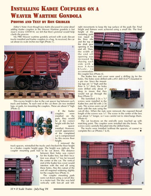
INSTALLING KADEE COUPLERS ON AWEAVER WARTIME GONDOLAPHOTOS AND TEXT BY RON GRIBLEREditor’s Note: Even though Jace Kahn discussed in some detailadding Kadee couplers to the Weaver Wartime gondola is lastissue’s review (OST#14), we felt that Ron’s pictorial would helpclarify the process.My PRR Weaver wartime gondola arrived with scale diecasttrucks installed and Kadee couplers in a bag. As received, the carsat about six scale inches too high [Photo 1].This excess height is due to the cast spacer lug between eachtruck and bolster. At each end of the car there are two moldedlugs, or pads, for mounting the couplers. These are about 1 ⁄8" high[Photo 2].If the Kadee2 couplers wereinstalled on thepads, they wouldbe at the correctheight with the bolsterspacerinstalled. However,overall appearanceof the completedcar is compromisedby this excess floorheight.I removed thetruck spacers, reinstalled the trucks and checked the floor heightto a Kadee coupler height gage. The height was right-on. Thecoupler mounting pads had to be cut down. The distancebetween their holes was correct310 • O <strong>Scale</strong> <strong>Trains</strong> - July/Aug ’04for the Kadee box, but their locationwas about 1 ⁄32" too far towardthe center of the car. The verticalend of the Kadee box cover wouldinterfere with the end sill usingthese holes. Also the cutout of theend sill required widening slightlyfor the coupler box [Photo 3].The coupler mounting padswere cut down using a cut-off discin a motor tool. The disc was heldvertically with fore-aft and left-1right movements to keep the top surface of the pads flat. Finalheight and flatness were achieved using a small file. The finalheight of themounting padswas equal tothe floor ribsand the top ofthe draft gearopening in theend sill. Then,the width ofthe end sillopening wasincreased byshaving eachside with anew X-Actoblade, toaccommodatethe coupler box [Photo 4].The Kadee box and cover were used a drilling jig for theholes. The holes were drilled with a #51 drill (0.67") mounted ina pin vise. Since the mountinglugs are 1 ⁄32" high and thefloor is 9 ⁄32" thick, the holeswere drilled only about 1 ⁄8"deep to insure that theywould not go through thefloor [Photo 5].The furnished 2-56 x 9 ⁄32"screws were installed in theKadee box and lid with 2-56nuts. The screws were cut off5flush with the nuts using thecut-off disc. When the nuts were removed, the exposed threadlength of the screws was 1 ⁄16". The screw in the center of the boxwas about 1 ⁄32" longer, so I was careful not to interchange them.[Photo 6]The cut locations on the end-sills were touched up withmatching paint. The couplers were installed into the boxes. Thescrews were carefully threaded into the drilled holes.The trucks were installed (without the spacers, of course) tocomplete the car [Photos 7 & 8].◆46


