Chain Link Fence Wind Load Guide for the ... - Hoover Fence
Chain Link Fence Wind Load Guide for the ... - Hoover Fence
Chain Link Fence Wind Load Guide for the ... - Hoover Fence

Create successful ePaper yourself
Turn your PDF publications into a flip-book with our unique Google optimized e-Paper software.
<strong>Chain</strong> <strong>Link</strong> <strong>Fence</strong><strong>Wind</strong> <strong>Load</strong> <strong>Guide</strong> <strong>for</strong> <strong>the</strong> Selection ofLine Post and Line Post Spacing(WLG 2445)Copyright, 2008<strong>Chain</strong> <strong>Link</strong> <strong>Fence</strong> Manufacturers InstituteAll rights reserved<strong>Chain</strong> <strong>Link</strong> <strong>Fence</strong> Manufacturers Institute10015 Old Columbia Road Suite B215Columbia, MD 21046Ph: 301-596-2583 Fax: 301-596-2594email: clfmihq@llol.comwww.chainlinkinfo.org
DISCLAIMERThe <strong>Wind</strong> <strong>Load</strong> <strong>Guide</strong> <strong>for</strong> <strong>the</strong> Selection of Line Post Spacings <strong>for</strong>Woven Wire <strong>Chain</strong> <strong>Link</strong> Fencing is published by <strong>the</strong> <strong>Chain</strong> <strong>Link</strong> <strong>Fence</strong>·Manufacturers Institute as a general in<strong>for</strong>mation service in <strong>the</strong> selectionof spacing <strong>for</strong> fencing line posts <strong>for</strong> chain link fence systems. However,because exposure, workmanship, soils, drainage, emplacement problems,wind and o<strong>the</strong>r wea<strong>the</strong>r conditions may vary, even at various locations ina single site, each application should be assessed by a qualifiedprofessional engineer. Accordingly, no representation or warranty ismade, and none should be implied, respecting <strong>the</strong> suitability or adequacy of<strong>the</strong> in<strong>for</strong>mation in this <strong>Guide</strong> <strong>for</strong> any particular application, nor is this<strong>Guide</strong> intended to establish industry "standards" respecting <strong>the</strong> selectionof spacing <strong>for</strong> fencing line posts, or <strong>for</strong> any purpose.
TABLE OF CONTENTS-lntroduction .. I ••• I •••••• II •••••••••••••••••••••••••••• II •••••• 11 ••••••••••••••••••••1.Factors Which Influence <strong>the</strong> Size and Spacing of Line Posts 2.Figure 1, Line Post Spacing Details 3eMethodology .... II •••••••••••••••••••••• II •••••••••••••••• I •• 1 •••••••• 1 •••••••••••••4 to 5.How to Use <strong>the</strong> <strong>Guide</strong> 6.Examples 117 to 9Tables 10 to 22• Table 1; Line Post Selection <strong>Guide</strong> <strong>for</strong> 70 Mph <strong>Wind</strong>• Table 2; Line Post Selection <strong>Guide</strong> <strong>for</strong> 85 Mph <strong>Wind</strong>• Table 3; Line Post Selection <strong>Guide</strong> <strong>for</strong> 90 Mph <strong>Wind</strong>• Table 4; Line Post Selection <strong>Guide</strong> <strong>for</strong> 100 Mph <strong>Wind</strong>• Table 5; Line Post Selection <strong>Guide</strong> <strong>for</strong> 110 Mph <strong>Wind</strong>• Table 6; Line Post Selection <strong>Guide</strong> <strong>for</strong> 120 Mph <strong>Wind</strong>• Table 7; Line Post Selection <strong>Guide</strong> <strong>for</strong> 130 Mph <strong>Wind</strong>• Table 8; Line Post Selection <strong>Guide</strong> <strong>for</strong> 140 Mph <strong>Wind</strong>• Table 9; Line Post Selection <strong>Guide</strong> <strong>for</strong> 150 Mph <strong>Wind</strong>• Table 10; Mesh and Fabric Size Coefficients ICf1"• Table 11; <strong>Wind</strong> Exposure Category Coefficients ICf2"• Table 12; Ice Exposure Effect Probability Coefficients ICf3"• Table 13; Line Post Material Properties Table• Table 14; <strong>Wind</strong> Speed I Velocity Pressure Table.Figure 6-1, Minimum Basic <strong>Wind</strong> Speeds Map 24.Metric Conversion Factors 25eAppendix 26 to 29eReferences· 30
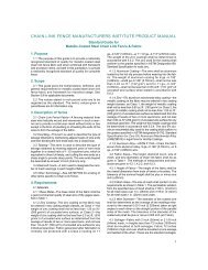
FACTORS WHICH INFLUENCETHE SIZE AND SPACINGS OF LINE POSTS*• HEIGHT OF FENCEThe height of <strong>the</strong> fence influences <strong>the</strong> actual amount of wind <strong>for</strong>ce that must be resisted by<strong>the</strong> post and <strong>the</strong> required anchorage to <strong>the</strong> ground. The fence height times <strong>the</strong> line postspacing sets <strong>the</strong> total <strong>for</strong>ce acting on a solid panel of <strong>the</strong> fence which is transferred to <strong>the</strong>line posts and <strong>the</strong>n into <strong>the</strong> footing.• STYLE AND SIZE OF FABRICThe style and size of fabric determines <strong>the</strong> net surface area of <strong>the</strong> solid fence panelexposed to <strong>the</strong> wind pressure which in turn must possess adequate tensile strength totransfer <strong>the</strong> developed loading to <strong>the</strong> supporting members of <strong>the</strong> fence assembly; Le.,line posts, top rail and base tension wire.• MATERIAL STRENGTH AND SHAPE OF POSTMaterial strength and shape of post determines <strong>the</strong> size of posts and <strong>the</strong>ir spacing whichwill provide <strong>the</strong> required resistance to <strong>the</strong> maximum expected wind <strong>for</strong>ces that maydevelop over <strong>the</strong> anticipated normal life-span of <strong>the</strong> installation and to remain serviceablesubsequent to <strong>the</strong> maximum wind event.• SOIL TYPE AS IT RELATES TO THE FOOTING SIZE AND DEPTHThe type of soil that will be encountered at <strong>the</strong> site of <strong>the</strong> fence installation will influence<strong>the</strong> post size and spacing by way of <strong>the</strong> passive soil pressures that can reasonably beexpected to resist <strong>the</strong> tendency <strong>for</strong> <strong>the</strong> line posts to overturn and also to remain in anessentially plumb position after <strong>the</strong> wind event. For footing design criteria, it is advisable tocontact a competent geotechnical professional <strong>for</strong> <strong>the</strong> appropriate soils in<strong>for</strong>mation at <strong>the</strong>particular site. The minimum depth of footings in accordance with ASTM F567 is 24" plusan additional 3" <strong>for</strong> each one (1) foot of fence height over 4 feet.• WIND PRESSURE<strong>Wind</strong> pressure is <strong>the</strong> most dominant factor that influences <strong>the</strong> post size and spacing sinceit is <strong>the</strong> only <strong>for</strong>ce that can reasonably be predicted and will be acting on <strong>the</strong> posts undernormal conditions. Reference Table 14 <strong>for</strong> values of various wind speeds.<strong>Wind</strong> pressure in itself is fur<strong>the</strong>r influenced by o<strong>the</strong>r factors; Le., geographicalregion, exposure, topography and ground surface features in <strong>the</strong> local area.*Reference Figure I, "LINE POST SPACING GUIDE DETAILS" <strong>for</strong> graphic description of factors.(2)
FENCE 5UEPORT SELECTION:-.y NOMINAL SPACING ¥- IJ.J C:sALVANIZED STEEL FIFE.-, OF LINE POSTS = 5 -I b.J COLD ROLLED FO~EDI MAX. RECOMMENDED STEEL 'C' SECTION.SPACING = 1""-0" Ac.J ~OT ROLLED STEEL 'I' SECTION~ , / ,___- £4 T -~ ~:'__ d) ALUMINUM PiPe (ALLOY Th-h~3)--~ :~ DIREX~~,~ALWAYS A~~DLJ TO Be AC~ORMAL TO PLANE OFFABRIC IN'£!RECTION TOWARD T~EFABRIC SIT OF LINE POST.IN, DETE~INED BYREC:sION, LO ATION, TOPOGRAP~Y,5URFACE F ATURES AND EXP05UREFOLLOUJINaJ ,A5CE 1-~& (FIC:sURE h -I)FENCE FABRIC----,.r-/--- TOP RAIL OR TENSION WIRE§.IIIIIIIIIIIIIIIIIII~:~~ .x SC~EDULE OF TYPES, SIZESh AND MATERIALS OF POST.LINE FOST - SEE TABLE 11 FORTENSION WIRE:: f-,,.........J'-----t--------+:Ik+::::IIII::"IIUND LEVEL ::IIIINOMINAL 2":CLEAR::IIIIUDCIRCULAR CONCRETE FOOTINGS EMBEDMENTDEPTH DEPENDENT ON TYPE OF SOIL THAT EXlsnON SITE. THE 0.0. ("0") OF THE FOOTING ISEXPRESSED AS 4 (pd) OR 3 (pd) (WHERE "pd" =POS·00) DEPENDING ON THE SIZE OF THE POSTDIAMETER.Ref. ASTM F567t .. WIRE C:sAe:.E.EFFECTIVE SURFACE AREA IN ONE (1) SQUAREFOOT OF FENCE PANEL T~AT RECEIveS POSITIVEEXTE~AL PRESSURE 15 DETERMINED BY T~E. NUMBER OF DI,OMONDS FOIlO1MED ·IN TI-IE AREAAND TI-IE DI,OMETER Of= TI-IE FABRIC WIRES(COATED OR UNCOATED):IAS!2UMPTIONS:a.) P05TS ARE SET IN CIRCULAR CONCRETEFOOTfNe:.& USINaJ 2~ P.S.I. AE. CONCRETE:EMBEDMENT INTO C:sROUND ACCORDING TOPREVAILINe:. C:sROUND CONDITIONS ANDLOCAL ~CTICE FOR TI-IE FOLLOWiNGsSOIL TYPES. (ALLOWABLE PASSIVE SOILPRESSURE)LOW PRES5URE- SANDY SOILSMEDIUM PRESSURE- SANDY CLAYSI-IIGJI-I PRESSURE- DENSE CLAYSFIGU~ ~.LIN~OST SPACING ~UI~TAfbQ(3)
The base program <strong>for</strong> <strong>the</strong> line post spacing was set up using <strong>the</strong> condition where <strong>Wind</strong> ExposureCategory "B" is <strong>the</strong> new normal situation replacing "An from ASCE 795; to account <strong>for</strong> <strong>the</strong> o<strong>the</strong>rtwo <strong>Wind</strong> Exposure Categories, "C", "0", and Table 11 was developed to list <strong>the</strong> Coefficient "Cf2"which is a ratio of <strong>the</strong> <strong>Wind</strong> Exposure Coefficient "Kz" <strong>for</strong> Exposure "B" to <strong>the</strong> o<strong>the</strong>r two exposurecoefficients as listed in ASCE 7-05, Table 6.3.In Table 12, Ice Effect Probability Coefficient ICf3" is included in <strong>the</strong> guide and was set up usingarbitrary values to permit <strong>the</strong> designer <strong>the</strong> ability to make an intelligent decision relative to hisperception and experience as to <strong>the</strong> probability that a severe icing condition may developconcurrent with <strong>the</strong> listed maximum wind speed <strong>for</strong> that particular geographical location <strong>for</strong> nonsolidfencing.Although Fig. 6-1 from ASCE 7-05 shows wind speed categor;rs in <strong>the</strong> range of 90 Mph to 150Mph, most all building codes in effect in <strong>the</strong> United States list design wind speeds ranging from70 Mph up to and including 120 Mph. This guide provides values of wind speeds that cover <strong>the</strong>entire range of velocities that may be encountered in all codes. For those intermediate windspeeds, it is acceptable to interpolate linearly.The user of this guide is advised that he may want to consider use of <strong>the</strong> full allowable stress of<strong>the</strong> material being employed which has a built-in Factor of Safety equivalent to 1.5; ie., 0.66 Fy,Reference Table 13. The user may also want to consider <strong>the</strong> merits of using a higher maximumallowable stress increase due to <strong>the</strong> fact that wind loadings usually may not be a sustainedcondition <strong>for</strong> that specific location where <strong>the</strong> fence installation is being planned.(5)
HOW TO USE THE GUIDEFor <strong>the</strong> fence fabric configuration and size of line post being considered, go to <strong>the</strong> appropriate table (Table1,2,3, .... ,9) that closely agrees with <strong>the</strong> maximum anticipated wind speed designated by <strong>the</strong> local codes <strong>for</strong>that geographical area where <strong>the</strong> fence installation is planned. From that table, find <strong>the</strong> value of "S" <strong>for</strong> <strong>the</strong>line post size and height desired. This value of "S" must <strong>the</strong>n be multiplied by correction coefficients thataccount <strong>for</strong> <strong>the</strong> type, size and mesh of <strong>the</strong> wire fabric, "Cf1" from Table 10; <strong>Wind</strong> exposure categorycoefficient, "Cf2" from Table 11; Icing effects probability coefficient, "Cf3" from Table 12.The recommended post spacing S' = S X Cf1 x Cf2 x Cf3EXAMPLE I:Select a line post spacing <strong>for</strong> a 12' high <strong>Chain</strong> <strong>Link</strong> fence, constructed of #9 gage wire, having a mesh sizepattern of 1-3/4". The installation location is <strong>for</strong> a park in an urban location in <strong>the</strong> Eastern U. S., where <strong>the</strong>wind exposure is considered, ' Exposure C'. Assume <strong>the</strong> local governing code indicates that <strong>the</strong> maximumwind speed <strong>for</strong> this application is 90 mph; localized icing effects are considered to be moderate. Onepossible line post material selection <strong>for</strong> this example is Group 1A, Schedule 40 steel pipe.From Table 3, <strong>Wind</strong> Speed 90 Mph, <strong>for</strong> a 4.0" outside diam. (3.5 nominal) pipe, <strong>the</strong> listed"s" value <strong>for</strong> a 12' high fence is 3.5.From Table 10, <strong>the</strong> Coefficient "Cf1", <strong>for</strong> a #9 gage, 1-3/4" mesh fabric = 6.4From Table 11, <strong>the</strong> Coefficient "Cf2", <strong>for</strong> a <strong>Wind</strong> Exposure Category C =0.67From Table 12, <strong>the</strong> Coefficient "Cf3", <strong>for</strong> Moderate Icing Effects = 0.85Thus <strong>the</strong> recommended maximum spacing <strong>for</strong> <strong>the</strong> 4" diam. Schedule 40, steel pipe post <strong>for</strong> <strong>the</strong> 12' highfence with a #9 gage wire and 1-3/4" mesh would be:S' =S X Cf1 x Cf2 x Cf3 =3.5 x 6.4 x 0.67 x 0.85 =12.75'The maximum recommended spacing would be 10'-0" c/c <strong>for</strong> <strong>the</strong> posts.(6)
EXAMPLE 2For a situation where <strong>the</strong> <strong>Wind</strong> Velocity is o<strong>the</strong>r than <strong>for</strong> one of <strong>the</strong> seven listed tables of line postspacings in <strong>the</strong> guide.Select a line post size and spacing <strong>for</strong> an 18' high chain link fence installation <strong>for</strong> which <strong>the</strong> fabric is to be a#9 gage - 1/2" mesh pattern. Assume <strong>the</strong> fence location is in an open terrain where <strong>the</strong> <strong>Wind</strong> ExposureCategory is "C" and <strong>the</strong> code listed maximum wind speed is 105 mph; icing effects potential is considered tobe moderate.From Table 10, <strong>the</strong> coefficient "Cfi" <strong>for</strong> mesh size and gage = 2.20From Table 11, <strong>the</strong> coefficient "Cf2" <strong>for</strong> wind exposure "c" = 0.69From Table 12, <strong>the</strong> coefficient "Cf3" <strong>for</strong> moderate icing effect = 0.85From Table 4, <strong>for</strong> a 100 Mph wind and an 18' high fence, select a Trialline post size spacing factor "5" =4.6 <strong>for</strong> a Group IA, 6-5/8" nom. diam. steel pipe.For this arrangement <strong>the</strong> maximum spacing would be <strong>the</strong> result of 4.6 x 2.20 x0.69 x 0.85 =5.94' ; This may not be an economical or practical spacing.There<strong>for</strong>e try <strong>the</strong> spacing <strong>for</strong> a Group JA, 8-5/8" nom. diam. steel pipe where "S" =9.2whose maximum recommended spacing would be 9.2/4.6 x 5.94' = 11.88'.If <strong>the</strong> maximum wind speed were 105 Mph condition <strong>the</strong> recommended spacing wouldbe 9.2/1 05 x 11 .88' =11.31' or 10'- 0" on centers, which would be more consistentwith <strong>the</strong> usual standard spacing followed in <strong>the</strong> industry.(7)
EXAMPLE 3:For a site location with a high wind condition and <strong>the</strong> design selection of anappropriate footing size and depth.Select a line post size, it's spacing and footing <strong>for</strong> a 10' high chain link fence that will consist of a #9gage 1-3/4" mesh fabric. Installation will be in Sou<strong>the</strong>rn Florida in an open terrain with a windexposure category "C" and a maximum wind velocity of 120 Mph. Soil condition is assumed to be amedium dense clay. (Actual soil properties should be established by a qualified geotechnicalengineer familiar with local soil conditions.)From Table 6 <strong>for</strong> 120 Mph wind and under 10' high fence and a trial sizeline post of Group lA, 3.5" nom. diam. steel pipe "8" ::: 2.0"Cf1" <strong>for</strong> <strong>the</strong> fabric size and gage = 6.4"Cf2" <strong>for</strong> <strong>the</strong> wind exposure category= 0.67"Cf3" <strong>for</strong> icing condition::: 1.0Thus <strong>the</strong> maximum spacing <strong>for</strong> <strong>the</strong> Group lA, 3.5" diam. pipe::: 2.0 x6.4 x 0.67 x 1.0 ::: 8.58'. This may not be an economical spacing; tryano<strong>the</strong>r trial size post.Checking <strong>the</strong> spacing <strong>for</strong> a Group lA, 4" nom. diam pipe where "S" :::2.9 Maximum spacing will be 2.9/2.0 x 8.58' = 12.44' use 10.0'For <strong>the</strong> 4" diam line post <strong>the</strong> minimum footing size is 4 x Pipe Diam per ASTMF-567 or 16"; However, it is recommended that footing size of 20" diam. beIJsed. The minimum depth of footing embedment in <strong>the</strong> medium dense claysoil is to be calculated as follows:LINE POST FOOTING PRESSUREAllowable soil bearing pressure (S1) <strong>for</strong> medium dense clay::: 6,000 psf*Factor of Safety = 1.2Design maximum allowable soil pressure::: S1/F.S.::: 6,000/F.S ::: 5,000 psf(8)
EXAMPLE 3 (Continued):Distance of applied <strong>for</strong>ce above footing "c" = 2/3H=0.67 x 10' = 6.67'Applied Force "P" = (1/Cf1) x Net Area of <strong>Fence</strong> x <strong>Wind</strong> Pressure where Cf1 is <strong>the</strong> Meshand Fabric Size Coefficient from Table 10 and <strong>the</strong> <strong>Wind</strong> Pressure is <strong>the</strong> Design <strong>Wind</strong>Pressure from Table 14.=(0.16 sf/sf) (100 sf) (29.43Ib/sf) =460 IbsDiameter of footing "d" =20" =1.67'Solving <strong>for</strong> "0" 0 =6P + (36p 2 + 240,000 dPC)1/22S1d= (6)(460) + [(36)(460)2 + (240,OOO)(1.67)(460)(6.67)p/2(2((5,000)(1.67)=2.27' minimum depth\of footing by calculation.However; footing depth by calculation does not agree with <strong>the</strong> minimum footing depth as setby ASTM F-567 which is 24" + [3" X (10'- 4.0')] = 24" + 18" = 42" which is <strong>the</strong> footingdepth that should be utilized.• Assumed allowable soil bearing pressure; actual value should be determined by appropriate means.(9)
LINE POSTTABLE 1LINE POST SELECTION GUIDE: WIND SPEED 70 MPHEXPOSURE CATEGORY "B"LINE POST MAXIMUM SPACING, S (FEET) FOR USE IN EQUATION: S' = S x Cfi x Cf2 x Cf3FENCE HEIGHT (FEET)SIZE 3 3.5 4 5 6 7 8 9 10 11 12 13 14 15 16 17 18 19 20Group IA: (ASTM F1043) Schedule 40 Steel Pipe, ASTM Fi083-06 Regular Grade (30,000 psi yield)1 718" 9.6 9.6 7.2 4.5 3.0 2.0 1.4 -- --- --- --- --- - --- - - --- --- ---2318" 16.6 16.6 12.7 8.0 5.4 3.9 2.8 2.1 1.6 1.2 --- --- -- --- - -- --- --- ---2718" 31.4 31.4 24.2 15.4 10.6 7.7 5.8 4.4 3.5 2.8 2.2 1.8 1.4 1.1 - - --- --- ---3112" 51.0 51.0 39.4 25.2 17.4 12.7 9.6 7.5 6.0 4.9 4.0 3.3 2.8 2.3 1.9 1.6 1.4 1.1 ---4 -- -- 54.9 35.0 24.3 17.8 13.5 10.6 8.5 6.9 5.7 4.8 4.1 3.5 3.0 2.5 2.2 1.9 1.66518" -- --... -- -- --- - 48.8 38.5 31.1 25.7 21.5 18.3 15.7 13.6 11.9 10.5 9.3 8.3 7.58518" --- -- --- - --- - --- -- -- 51.0 42.8 36.4 31.4 27.3 24.0 21.2 18.8 16.9 15.2Group IC: (ASTM F1043) Steel Pipe (50,000 psi yield)1 518" 9.7 9.4 7.0 4.2 2.6 1.7 1.0 -- --- - --- -- --- --- - - --- -- ---1 718" 13.9 13.7 10.4 6.4 4.2 2.8 1.9 1.3 --- -- --- --- --- --- - --- --- --- ---2318" 24.1 24.1 18.4 11.6 7.8 5.5 4.0 3.0 2.2 1.6 1.2 --- --- --- - - --- --- ---2718" 43.4 43.4 33.4 21.2 14.5 10.5 7.9 6.0 4.7 3.7 2.9 2.3 1.8 1.4 1.1 - --- --- ---3112" -- --- 51.2 32.6 22.5 16.4 12.4 9.6 7.6 6.2 5.0 4.1 3.4 2.8 2.3 1.9 1.6 1.3 1.04 --- -- -- 43.5 30.1 22.0 16.7 13.0 10.4 8.5 7.0 5.8 4.9 4.1 3.5 3.0 2.5 2.1 1.8Group IA: Intermediate Grade Schedule 40 Steel Pipe, ASTM F 1083-06 Intermediate Grade (50,000 psi yield)6518" ..._- -- -- -- --- -- --- --- 51.6 42.5 35.6 30.1 25.8 22.3 19.5 17.1 15.1 13.4 11.98518" --- - -- -- --- -- --- --- --- -- --- --- 51.8 44.9 39.3 34.7 30.7 27.4 24.6Group IA: High Strength 83000 Grade Schedule 40 Pipe, ASTM F 1083-06 High Strength Grade (83,000 psi yield)1 518" 19.3 18.8 14.2 8.6 5.5 3.5 2.3 1.4 --- - --- --- - --- - - --- --- ...--1718" 26.7 26.5 20.1 12.4 8.2 5.6 3.8 2.6 1.8 1.1 --- --- - --- - -- - --- ---2318" 46.0 46.0 35.2 22.2 15.0 10.7 7.8 5.8 4.3 3.3 2.4 1.7 1.2 -- -- -- ...-- -- ---2718" ..-- - --- 42.6 29.3 21.2 15.9 12.3 9.6 7.7 6.1 4.9 4.0 3.2 2.5 2.0 1.5 1.1 ---3112" --- - --- - 48.1 35.1 26.6 20.8 16.6 13.4 11.0 9.1 7.6 6.4 5.4 4.5 3.8 3.2 2.64 - -- --- - --- 49.1 37.4 29.3 23.5 19.2 15.9 13.3 11.3 9.6 8.2 7.0 6.1 5.2 4.5GROUP II: (ASTM F1043) High Strength Cold Rolled Formed C-Shape (50,000 psi yield)1718" x 1 518"x.105 10.3 10.3 7.8 4.8 3.2 2.2 1.5 1.1 --- --- --- --- -- -- - - - --- ---1 718" x 1 518"x.121 17.5 17.5 13.3 8.3 5.5 3.8 2.7 1.9 1.4 - --- -- -- --- - - -- --- ---2114" x 1 518" x.121 20.2 20.1 15.3 9.5 6.4 4.4 3.1 2.2 1.6 1.1 --- --- - --- - - --- --- ---3114"x2 112" x .130 49.8 49.7 37.7 23.5 15.7 10.9 7.7 5.5 3.9 2.7 1.8 1.1 -- --- - - - --- ----GROUP III: (ASTM F1043) Hot Rolled H-Beam (50,000 psi yield)2 114" x 1 518" 38.6 38.6 29.7 18.8 12.8 9.2 6.8 5.2 4.0 3.1 2.4 1.9 1.4 1.1 - - - --- --.o'\"'""--
TABLE 2LINE POST SELECTION GUIDE: WIND SPEED 85 MPHEXPOSURE CATEGORY "B"LINE POST MAXIMUM SPACING, S (FEET) FOR USE IN EQUATION: S· = S x Cf1 x Cf2 x Cf3FENCE HEIGHT (FEET)SIZE 3 3.5 4 5 6 7 8 9 10 11 12 13 14 15 16 17 18 19 20Group IA: (ASTM F1043) Schedule 40 Steel Pipe, ASTM F1083-06 Regular Grade (30,000 psi yield)1 7/8" 8.9 6.5 4.9 3.0 2.0 1.4 -- - --- --- --- --.. --- --- --- --- --- --- ---23/8" 15.5 11.3 8.6 5.4 3.7 2.6 1.9 1.4 1.1 --- --- --- --- --- -- --- -- ..-- ---LINE POST27/8" 29.3 21.5 16.4 10.4 7.2 5.2 3.9 3.0 2.4 1.9 1.5 1.2 --- --- -- --- --- --- ---31/2" 47.6 35.0 26.7 17.1 11.8 8.6 6.5 5.1 4.1 3.3 2.7 2.2 1.9 1.6 1.3 1.1 --- --- ---4 --- 48.6 37.2 23.8 16.5 12.0 9.2 7.2 5.8 4.7 3.9 3.3 2.8 2.3 2.0 1.7 1.5 1.3 1.165/8" --- --- --- --- 58.9 43.2 33.1 26.1 21.1 17.4 14.6 12.4 10.7 9.3 8.1 7.1 6.3 5.6 5.185/8" -- --- -- -- -- -- --- 51.7 41.9 34.6 29.0 24.7 21.3 18.5 16.2 14.4 12.8 11.4 10.3Group IC: (ASTM .F1043) Steel Pipe (50,000 psi yield)1 5/8" 8.8 6.4 4.8 2.9 1.8 1.1 --- -- --- -- --- --- -- --- -- -- -- --- ---17/8" 12.8 9.3 7.0 4.3 2.8 1.9 1.3 --- --- -- --- --- --- --- --- --- -- --- ---23/8" 22.4 16.4 12.5 7.8 5.3 3.7 2.7 2.0 1.5 1.1 --- --- --- --- --- --- --- ---.. ---27/8" 40.5 29.7 22.7 14.4 9.9 7.1 5.3 4.1 3.2 2.5 2.0 1.6 1.2 --- --- -- --- --- ---31/2" --- 45.4 34.7 22.1 15.3 11.1 8.4 6.5 5.2 4.2 3.4 2.8 2.3 1.9 1.6 1.3 1.1 --- ---4 --- --- 46.2 29.5 20.4 14.9 11.3 8.8 7.1 5.8 4.7 3.9 3.3 2.8 2.4 2.0 1.7 1.4 1.2Group IA: Intermediate Grade Schedule 40 Steel Pipe, ASTM F 1083-06 Intermediate Grade (50,000 psi yield)65/8" --- --- --- - -- -- 55.0 43.4 35.0 28.8 24.1 20.4 17.5 15.1 13.2 11.6 10.2 9.1 8.185/8" -- --- --- - --- --- --- --- --- 57.4 48.1 40.9 35.1 30.5 26.7 23.5 20.8 18.6 16.7Group IA: High Strength 83000 Grade Schedule 40 Pipe, ASTM F 1083-06 High Strength Grade (83,000 psi yield)1 5/8" 17.6 12.8 9.6 5.8 3.7 2.4 1.5 --- --- --- --- --- --- --- - ..-- -- -- ---17/8" 24.7 18.0 13.6 8.4 5.5 3.8 2.6 1.8 1.2 --- --- --- -- --- -- - -- --23/8" 42.8 31.3 23.8 15.0 10.2 7.2 5.3 3.9 2.9 2.2 1.6 1.2 -- --- - - - --- --27/8" -- 59.6 45.5 28.9 19.9 14.4 10.8 8.3 6.5 5.2 4.2 3.3 2.7 2.1 1.7 1.3 1.0 --- --31/2" --- --- --- 47.2 32.6 23.8 18.0 14.1 11.2 9.1 7.5 6.2 5.2 4.3 3.6 3.0 2.6 2.1 1.84 -- --- --- - 45.6 33.3 25.4 19.9 15.9 13.0 10.8 9.0 7.6 6.5 5.6 4.8 4.1 3.5 3.0GROUP II: (ASTM F1043) High Strength Cold Rolled Formed C-Shape (50,000 psi yield)17/8"x 1 5/8"x.105 9.5 7.0 5.3 3.3 2.2 1.5 1.0 - --- --- -- -- -- --- - -- - -- --1 7/8" x 1 5/8"x.121 16.2 11.8 9.0 5.6 3.7 2.6 1.8 1.3 --- --- --- -- --- -- --- --- -- ---2 1/4" x 1 5/8" x.121 18.7 13.7 10.4 6.5 4.3 3.0 2.1 1.5 1.1 -- --- ---- - - --- - -- -31/4" x 21/2" x .130 46.2 33.7 25.6 16.0 10.7 7.4 5.2 3.7 2.6 1.8 1.2 -- - -- - -- - --- ---GROUP III: (ASTM F1043) Hot Rolled H-Beam (50,000 psi yield)2 1/4" x 1 5/8" 36.0 26.4 20.1 12.7 8.7 6.3 4.6 3.5 2.7 2.1 1.6 1.3 - - - - - - -...-.oror--
LINE POSTTABLE 3LINE POST SELECTION GUIDE: WIND SPEED 90 MPHEXPOSURE CATEGORY "8"LINE POST MAXIMUM SPACING, S (FEET) FOR USE IN EQUATION: S' = S x Cf1 x Cf2 x Cf3FENCE HEIGHT (FEET)SIZE 3 3.5 4 5 6 7 8 9 10 11 12 13 14 15 16 17 18 19 20Group IA: (ASTM F1043) Schedule 40 Steel Pipe, ASTM F1083·06 Regular Grade (30,000 psi yield)17/8" 8.0 5.8 4.4 2.7 1.8 1.2 --- --- --- --- -- --- --- --- --- - - - ---23/8" 13.8 10.1 7.7 4.8 3.3 2.3 1.7 1.3 -- --- --- --- --- --- --- -- - --- ---27/8" 26.1 19.2 14.7 9.3 6.4 4.6 3.5 2.7 2.1 1.7 1.3 1.1 -- --- .._- --- -- - ..--31/2" 42.5 31.2 23.9 15.2 10.5 7.7 5.8 4.5 3.6 2.9 2.4 2.0 1.7 1.4 1.2 --- --- -- ---4 59.1 43.4 33.2 21.2 14.7 10.7 8.2 6.4 5.1 4.2 3.5 2.9 2.5 2.1 1.8 1.5 1.3 1.1 ---65/8" --- -- --- -- 52.5 38.6 29.5 23.3 18.8 15.5 13.0 11.1 9.5 8.3 7.2 6.4 5.6 5.0 4.585/8" --- --- --- -- --- --- . 58.4 46.1 37.3 30.8 25.9 22.0 19.0 16.5 14.5 12.8 11.4 10.2 9.2Group IC: (ASTM F1043) Steel Pipe (50,000 psi yield)15/8" 7.9 5.7 4.3 2.5 1.6 1.0 --- --- --- --- --- --- - --- -- -- -- -- ---1 7/8" 11.4 8.3 6.3 3.9 2.5 1.7 1.1 --- --- --- --- --- - ...- --- --- --- --- --- ---23/8" 20.0 14.6 11.1 7.0 4.7 3.3 2.4 1.8 1.3 --- --- --- -- --- --- --- --- --- ---27/8" 36.1 26.5 20.2 12.8 8.8 6.4 4.8 3.6 2.8 2.2 1.8 1.4 1.1 - --- ...-- --- -- ---31/2" 55.2 40.5 31.0 19.7 13.6 9.9 7.5 5.8 4.6 3.7 3.0 2.5 2.1 1.7 1.4 1.2 --- - ---4 --- 53.9 41.2 26.3 18.2 13.3 10.1 7.9 6.3 5.1 4.2 3.5 3.0 2.5 2.1 1.8 1.5 1.3 1.1Group IA: Intermediate Grade Schedule 40 Steel Pipe, ASTM F 1083-06 Intermediate Grade (50,000 psi yield)65/8" --- -- --- --- -- --- 49.1 38.7 31.2 25.7 21.5 18.2 15.6 13.5 11.8 10.3 9.1 8.1 7.285/8" --- --- --- --- -- .. _- --- -- ---.. 51.2 42.9 36.5 31.3 27.2 23.8 21.0 18.6 16.6 14.9Group IA: High Strength 83000 Grade Schedule 40 Pipe, ASTM F 1083-06 High Strength Grade (83,000 psi yield)1 5/8" 15.7 11.4 8.6 5.2 3.3 2.1 1.4 --- --- --- --- --- -- --- --- -- --- - ---17/8" 22.0 16.0 12.1 7.5 4.9 3.4 2.3 1.6 1.1 --- --- --- -- --- --- -- -- --- ---23/8" 38.2 27.9 21.3 13.4 9.1 6.5 4.7 3.5 2.6 2.0 1.5 1.1 --- --- --- --- -- - ---27/8" -- 53.1 40.6 25.8 17.7 12.8 9.6 7.4 5.8 4.6 3.7 3.0 2.4 1.9 1.5 1.2 --- - ---31/2" -- --- --- 42.1 29.1 21.2 16.1 12.6 10.0 8.1 6.7 5.5 4.6 3.9 3.2 2.7 2.3 1.9 1.64 -- --- --- 58.7 40.6 29.7 22.6 17.7 14.2 11.6 9.6 8.1 6.8 5.8 5.0 4.3 3.7 3.2 2.7GROUP II: (ASTM F1043) High Strength Cold Rolled Formed C-Shape (50,000 psi yield)17/8" x 1 5/8"x.105 8.5 6.2 4.7 2.9 1.9 1.3 --- -- -- --- --- --- --- -- - --- -- - ---1 7/8" x 1 5/8"x.121 14.5 10.6 8.0 5.0 3.3 2.3 1.6 1.2 - -- -- --- - ..- -- - - --- - ---21/4" x 1 5/8" x.121 16.7 12.2 9.3 5.8 3.9 2.7 1.9 1.4 - --- -- --- --- --- -- -- -- -- ---31/4" x 21/2" x .130 41.2 30.1 22.8 14.2 9.5 6.6 4.7 3.3 2.4 1.6 1.1 --- --- --- -- -- --- -- ----GROUP III: (ASTM F1043) Hot Rolled H·Beam (50,000 psi yield)2 1/4" x 1 5/8" 32.1 23.5 18.0 11.4 7.8 5.6 4.1 3.1 2.4 1.9 1.5 1.1 - - - - - - ----.....Ṉ--
'.; ," .... -:TABLE 4LINE POST SELECTION GUIDE: WIND SPEED 100 MPHEXPOSURE CATEGORY "B"LINE POST MAXIMUM SPACING, S (FEET) FOR USE IN EQUATION: S· = S x Cf1 x Cf2 x Cf3FENCE HEIGHT (FEET)SIZE 3 3.5 4 5 6 7 8 9 10 11 12 13 14 15 16 17 18 19 20Group IA: (ASTM F1043) Schedule 40 Steel Pipe, ASTM F1083-06 Regular Grade (30,000 psi yield)LINE POST4.7 3.6 2.2 -_....-1 7/8" 6.41.4 ---- --- ---- --- ---- -- ........ ........ ..........------ ----23/8" 11.2 8.2 6.2 3.9 2.7 1.9 1.4 1.0 ---- ---- _..- ---- - ---- --- --- - -- -------- -- ---- ---- ---- --- ---- ----27/8"31/2"465/8"21.2 15.5 11.9 7.6 5.2 3.8 2.8 2.2 1.7 1.4 1.134.4 25.3 19.3 12.3 8.5 6.2 4.7 3.7 2.9 2.4 2.0 1.6 1.3 1.1 ---- ---- -- -- ----47.9 35.1 26.9 17.2 11.9 8.7 6.6 5.2 4.2 3.4 2.8 2.4 2.0 1.7 1.5 1.2 1.1 --- -------- -- ---- ---- 42.5 31.2 23.9 18.9 15.3 12.6 10.5 9.0 7.7 6.7 5.8 5.2 4.6 4.1 3.7---- --- --- ---- ---- ---- 47.3 37.4 30.2 25.0 21.0 17.9 15.4 13.4 11.7 10.4 9.2 8.3 7.485/8"Group IC: (ASTM F1043) Steel Pipe (50,000 psi yield)15/8" 6.4 4.6 3.4 2.1 1.3 - ---- --- ---- ---- ---- --- --- ---- ---- -- -- --- ----17/8" 9.2 6.7 5.1 3.1 2.0 1.4 ---- --- ---- --- ---- ---- --- ---- ---- ---- --- ---- ----23/8" 16.2 11.8 9.0 5.7 3.8 2.7 2.0 1.4 1.1 ---- ---- ---- --- ---- --- ---- - ---- ----27/8" 29.2 21.4 16.4 10.4 7.1 5.1 3.8 2.9 2.3 1.8 1.4 1.1 -- ---- - ---- - ---- ----31/2"44.7 32.8 25.1 16.0 11.0 8.0 6.1 4.7 3.7 3.0 2.5 2.0 1.7 1.4 1.1 ---- -- ---- ----459.5 43.7 33.4 21.3 14.7 10.8 8.2 6.4 5.1 4.2 3.4 2.8 2.4 2.0 1.7 1.4 1.2 1.0 ----Group IA: Intermediate Grade Schedule 40 Steel Pipe, ASTM F 1083-06 Intermediate Grade (50,000 psi yield)65/8" --- --- --- --- ---- 52.0 39.7 31.3 25.3 20.8 17.4 14.8 12.7 10.9 9.5 8.4 7.4 6.6 5.885/8" --- ---- --- ---- ---- ---- ---- ---- \ 50.3 41.5 34.7 29.5 25.4 22.0 19.3 17.0 15.1 13.4 12.0Group IA: High Strength 83000 Grade Schedule 40 Pipe, ASTM F 1083-06 High Strength Grade (83,000 psi yield)15/8" 12.7 9.2 6.9 4.2 2.7 1.7 1.1 ---- ---- ---- ---- ---- ---- ---- ---- ---- - ---- ----17/8" 17.8 13.0 9.8 6.1 4.0 2.7 1.9 1.3 -- ---- ---- ---- --- ---- - ---- --- ---- ----23/8"30.9 22.6 17.2 10.9 7.4 5.2 3.8 2.8 2.1 1.6 1.2 ---- -- ---- --- ---- - -- ----27/8" 58.7 43.0 32.9 20.9 14.4 10.4 7.8 6.0 4.7 3.8 3.0 2.4 1.9 1.6 1.2 ---- - --- ----31/2"---- --- 53.5 34.1 23.6 17.2 13.0 10.2 8.1 6.6 5.4 4.5 3.7 3.1 2.6 2.2 1.8 1.5 1.34---- --- --- 47.6 32.9 24.1 18.3 14.4 11.5 9.4 7.8 6.5 5.5 4.7 4.0 3.4 3.0 2.6 2.2GROUP II: (ASTM F1043) High Strength Cold Rolled Formed C-Shape (50,000 psi yield)1 7/8" x 1 5/8"x.105 6.9 5.0 3.8 2.4 1.6 1.1 ---- --- ---- ---- ---- ---- ---- ---- ---- -- -- ---- ----1 7/8" x 1 5/8"x.121 11.7 8.6 6.5 4.1 2.7 1.9 1.32 1/4" x 1 5/8" x.121 13.5 9.9 7.5 4.7 3.1 2.2 1.5 1.1--- ---- ---- ---- ---- ---- --- --- -- -- ---- -------- --- ---- ---- ---- ---- -- ---- --- ---- -------- --- --- ---- --- ---- --- ----31/4"x21/2"x .130 33.4 24.4 18.5 11.5 7.7 5.3 3.8 2.7 1.9 1.3-GROUP III: (ASTM F1043) Hot Rolled H-Beam (50,000 psi yield)2 1/4" x 1 5/8" 26.0 19.1 14.5 9.2 6.3 4.5 3.4 2.5 2.0 1.5 1.2 -- - - - -- - - --.........C'j.~'-"
LINE POSTTABLE 5LINE POST SELECTION GUIDE: WIND SPEED 110 MPHEXPOSURE CATEGORY "B"LINE POST MAXIMUM SPACING, S (FEET) FOR USE IN EQUATION: S· =S x Cf1 x Cf2 x Cf3FENCE HEIGHT (FEET)SIZE 3 3.5 4 5 6 7 8 9 10 11 12 13 14 15 16 17 18 19 20Group IA: (ASTM F1043) Schedule 40 Steel Pipe, ASTM F1083·06 Regular Grade (30,000 psi yield)17/8" 5.3 3.9 2.9 1.8 1.2 -- --- --- --- --- --- --- --- -- --- --- --- --- ---23/8" 9.2 6.8 5.1 3.2 2.2 1.6 1.1 --- --- --- --- --- --- --- --- --- --- --- ---27/8" 17.5 12.8 9.8 6.2 4.3 3.1 2.3 1.8 1.4 1.1 --- -_. --- --- --- --- --- -- ---31/2" 28.4 20.9 16.0 10.2 7.0 5.1 3.9 3.0 2.4 2.0 1.6 1.3 1.1 --- --- --- --- -- ---4 39.6 29.0 22.2 14.2 9.8 7.2 5.5 4.3 3.4 2.8 2.3 1.9 1.6 1.4 1.2 1.0 -- --- ---65/8" --- --- --- 50.7 35.2 25.8 19.7 15.6 12.6 10.4 8.7 7.4 6.4 5.5 4.8 4.3 3.8 3.4 3.085/8" --- --- --- --- --- 51.1 39.1 30.9 25.0 20.6 17.3 14.8 12.7 11.1 9.7 8.6 7.6 6.8 6.2Group IC: (ASTM F1043) Steel Pipe (50,000 psi yield)15/8" 5.3 3.8 2.8 1.7 1.1 --- --- --- --- --. --- --. --- --- --- --- --- - ---17/8" 7.6 5.6 4.2 2.6 1.7 1.1 --- --- --- --- --- --- --- --- --- --- --- --- ---23/8" 13.4 9.8 7.4 4.7 3.2 2.2 1.6 1.2 --. --- --- --- --- --- --- --- --- --. ---27/8" 24.2 17.7 13.5 8.6 5.9 4.3 3.2 2.4 1.9 1.5 1.2 --- --- ---. --- --- --- --- ---31/2" 37.0 27.1 20.7 13.2 9.1 6.6 5.0 3.9 3.1 2.5 2.0 1.7 1.4 1.1 -- ---. --- --- ---4 49.2 36.1 27.6 17.6 12.2 8.9 6.8 5.3 4.2 3.4 2.8 2.4 2.0 1.7 1.4 1.2 1.0 --- ----Group IA: Intermediate Grade Schedule 40 Steel Pipe, ASTM F 1083-06 Intermediate Grade (50,000 psi yield)65/8" --- --- --- .--. 58.6 43.0 32.8 25.9 20.9 17.2 14.4 12.2 10.5 9.0 7.9 6.9 6.1 5.4 4.885/8" --- -- --- --- --- --- --- 51.4 41.5 34.3 28.7 24.4 21.0 18.2 15.9 14.0 12.4 11.1 9.9Group IA: High Strength 83000 Grade Schedule 40 Pipe, ASTM F 1083-06 High Strength Grade (83,000 psi yield)15/8" 10.5 7.6 5.7 3.5 2.2 1.4 --- --- -- --. --- --- --- --- -- --- -.- --- ---17/8" 14.7 10.7 8.1 5.0 3.3 2.3 1.6 1.1 --- --- --- --- --- --- --- --- -- --- ---23/8" 25.6 18.7 14.2 9.0 6.1 4.3 3.2 2.3 1.8 1.3 -- --- --- --- --- --- --- --- ---27/8" 48.5 35.6 27.2 17.3 11.9 8.6 6.5 5.0 3.9 3.1 2.5 2.0 1.6 1.3 1.0 --- --- -- ---31/2" -.- 57.8 44.2 28.2 19.5 14.2 10.8 8.4 6.7 5.4 4.5 3.7 3.1 2.6 2.2 1.8 1.5 1.3 1.14 .-- --- --- 39.3 27.2 19.9 15.1 11.9 9.5 7.8 6.4 5.4 4.6 3.9 3.3 2.8 2.5 2.1 1.8GROUP II: (ASTM F1043) High Strength Cold Rolled Formed C-Shape (50,000 psi yield)1 7/8" x 1 5/8"x.105 5.7 4.2 3.1 2.0 1.3 --- --- .-- -- --- --- --- --- --- -- --- --- - ---1 7/8" x 1 5/8"x.121 9.7 7.1 5.4 3.3 2.2 1.6 1.1 --- --- -- --- --- .-- --- -- --- --- -- ---2 1/4" x 1 5/8" x.121 11.2 8.2 6.2 3.9 2.6 1.8 1.3 --- --- .-. --- --. --- ---. --- --- -- ----31/4" x 21/2" x .130 27.6 20.1 15.3 9.5 6.4 4.4 3.1 2.2 1.6 1.1 --- --- --- --- --- --- - --- .---GROUP III: (ASTM F1043) Hot Rolled H-Beam (50,000 psi yield)2 1/4" x 1 5/8" 21.5 15.8 12.0 7.6 5.2 3.7 2.8 2.1 1.6 1.3 - -- --- --- - -- - --- -~..-"'-"'
LINE POSTTABLE 6LINE POST SELECTION GUIDE: WIND SPEED 120 MPHEXPOSURE CATEGORY "B"LINE POST MAXIMUM SPACING, S (FEET) FOR USE IN EQUATION: S· = S x Cf1 x Cf2 x Cf3FENCE HEIGHT (FEET)SIZE 3 3.5 4 5 6 7 8 9 10 11 12 13 14 15 16 17 18 19 20Group IA: (ASTM F1043) Schedule 40 Steel Pipe, ASTM F1083·06 Regular Grade (30,000 psi yield)17/8" 4.5 3.3 2.5 1.5 1.0 --- --- --- --- --- --- --- --- --- -- --- --- --- ---23/8" 7.8 5.7 4.3 2.7 1.8 1.3 --- -- --- --- --- --- -- --- - -- --- .._- ---27/8" 14.7 10.8 8.2 5.2 3.6 2.6 2.0 1.5 1.2 --- --- --- --- - - -- -- --- ---31/2" 23.9 17.5 13.4 8.6 5.9 4.3 3.3 2.6 2.0 1.7 1.4 1.1 .._- --- -- --- --- --- ---4 33.2 24.4 18.7 11.9 8.3 6.0 4.6 3.6 2.9 2.4 2.0 1.6 1.4 1.2 1.0 --- --- --- ---65/8" -- --- - 42.6 29.5 21.7 16.6 13.1 10.6 8.7 7.3 6.2 5.3 4.6 4.1 3.6 3.2 2.8 2.585/8" -- --- - --- 58.5 42.9 32.9 25.9 21.0 17.3 14.6 12.4 10.7 9.3 8.2 7.2 6.4 5.7 5.2Group IC: (ASTM F1043) Steel Pipe (50,000 psi yield)15/8" 4.4 3.2 2.4 1.4 -- --- --- -- --- -- --- --- --- --- --- --- --- --- ---1 7/8" 6.4 4.7 3.5 2.2 1.4 -- --- --- --- --- --- --- --- --- --- --- --- --- ---23/8" 11.2 8.2 6.3 3.9 2.7 1.9 1.4 1.0 --- --- --- --- --- -- --- --- --- --- ---27/8" 20.3 14.9 11.4 7.2 4.9 3.6 2.7 2.0 1.6 1.3 --- -- --- --- --- -- --- --- -31/2" 31.1 22.8 17.4 11.1 7.7 5.6 4.2 3.3 2.6 2.1 1.7 1.4 1.2 --- --- --- --- --- ---4 41.3 30.3 23.2 14.8 10.2 7.5 5.7 4.4 3.5 2.9 2.4 2.0 1.7 1.4 1.2 1.0 --- -- ----Group IA: Intermediate Grade Schedule 40 Steel Pipe, ASTM F 1083-06 Intermediate Grade (50,000 psi yield)65/8" -- - ...- -- -- 49.2 36.1 27.6 21.8 17.6 14.5 12.1 10.3 8.8 7.6 6.6 5.8 5.1 4.6 4.185/8" --- --- -- --- -- -- 54.7 43.2 34.9 28.8 24.1 20.5 17.6 15.3 13.4 11.8 10.5 9.3 8.4Group IA: High Strength 83000 Grade Schedule 40 Pipe, ASTM F 1083-06 High Strength Grade (83,000 psi yield)15/8" 8.8 6.4 4.8 2.9 1.9 1.2 -- --- --- --- -- --- --- - -- --- --- --- ---17/8" 12.4 9.0 6.8 4.2 2.8 1.9 1.3 --- --- -- --- --- --- --- --- -- --- --- --23/8" 21.5 15.7 12.0 7.5 5.1 3.6 2.7 2.0 1.5 1.1 --- --- -- - --- --- --- --- --27/8" 40.7 29.9 22.8 14.5 10.0 7.2 5.4 4.2 3.3 2.6 2.1 1.7 1.3 1.1 --- --- --- --- ---31/2" --- 48.6 37.2 23.7 16.4 11.9 9.1 7.1 5.6 4.6 3.7 3.1 2.6 2.2 1.8 1.5 1.3 1.1 ---4 -- --- 51.7 33.0 22.9 16.7 12.7 10.0 8.0 6.5 5.4 4.5 3.8 3.3 2.8 2.4 2.1 1.8 1.5GROUP II: (ASTM F1043) High Strength Cold Rolled Formed C-Shape (50,000 psi yield)17/8" x 1 5/8"x.105 4.8 3.5 2.6 1.6 1.1 -- --- --- - --- --- -- --- --- - --- --- - ---17/8" x 1 5/8"x.121 8.1 5.9 4.5 2.8 1.9 1.3 --- - ... --- --- -- --- --- -- --- --- --- --- --21/4" x 15/8" x.121 9.4 6.9 5.2 3.2 2.2 1.5 1.1 -- --- --- -- --- --- - --- -- --- -- -31/4" x 21/2" x .130 23.2 16.9 12.8 8.0 5.3 3.7 2.6 1.9 1.3 - --- --- --- - --- --- -- - ----GROUP III: (ASTM F1043) Hot Rolled H-Beam (50,000 psi yield)2 1/4" x 1 5/8" 18.1 13.2 10.1 6.4 4.4 3.1 2.3 1.8 1.4 1.1 -- - - -- - - - - ----- LO.............
TABLE 8LINE POST SELECTION GUIDE: WIND SPEED 140 MPHEXPOSURE CATEGORY "B"LINE POST MAXIMUM SPACING, S (FEET) FOR USE IN EQUATION: S' =S x Cf1 x Cf2 x Cf3FENCE HEIGHT (FEET)SIZE 3 3.5 4 5 6 7 8 9 10 11 12 13 14 15 16 17 18 19 20Group IA: (ASTM F1043) Schedule 40 Steel Pipe, ASTM F1083-06 Regular Grade (30,000 psi yield)17/8" 3.3 2.4 1.8 1.1 -- --- -- --- --- --- --- --- --- --- ---... --- --- -- ---LINE POST23/8" 5.7 4.2 3.2 2.0 1.4 --- - -- --- --- --- --- -- --- --- --- --- --- ---27/8" 10.8 7.9 6.1 3.9 2.6 1.9 1.4 1.1 --- --- -- --- --- -- --- --- --- - ---31/2" 17.6 12.9 9.9 6.3 4.3 3.2 2.4 1.9 1.5 1.2 -- --- --- --- --- --- --- -- ---4 24.4 17.9 13.7 8.8 6.1 4.4 3.4 2.6 2.1 1.7 1.4 1.2 1.0 --- - --- - --- ---65/8" --- -- 48.9 31.3 21.7 15.9 12.2 9.6 7.8 6.4 5.4 4.6 3.9 3.4 3.0 2.6 2.3 2.1 1.985/8" --- --- --- --- 42.9 31.5 24.1 19.1 15.4 12.7 10.7 9.1 7.8 6.8 6.0 5.3 4.7 4.2 3.8Group IC: (ASTM F1043) Steel Pipe (50,000 psi yield)1 5/8" 3.3 2.4 1.8 1.1 -- --- - - -- --- --- ..-- -- --- -- - --- -- ---1 7/8" 4.7 3.4 2.6 1.6 1.0 --- -- - --- --- --- --- --- --- --- --- --- --- ---23/8" 8.3 6.0 4.6 2.9 2.0 1.4 1.0 - -- --- -- --- --- --- --- --- --- --- ---27/8" 14.9 10.9 8.4 5.3 3.6 2.6 2.0 1.5 1.2 --- -- --- --- --- --- --- --- --- --31/2" 22.8 16.7 12.8 8.2 5.6 4.1 3.1 2.4 1.9 1.5 1.3 1.0 --- --- --- --- --- -- ---4 30.3 22.3 17.0 10.9 7.5 5.5 4.2 3.3 2.6 2.1 1.7 1.5 1.2 1.0 --- --- --- -- ----Group IA: Intermediate Grade Schedule 40 Steel Pipe, ASTM F 1083-06 Intermediate Grade (50,000 psi yield)65/8" --- --- -- 52.1 36.2 26.5 20.3 16.0 12.9 10.6 8.9 7.5 6.5 5.6 4.9 4.3 3.8 3.3 3.085/8" --- --- --- --- --- 52.5 40.2 31.7 25.6 21.1 17.7 15.1 12.9 11.2 9.8 8.7 7.7 6.9 6.1Group IA: High Strength 83000 Grade Schedule 40 Pipe; ASTM F 1083-06 High Strength Grade (83,000 psi yield)1 5/8" 6.5 4.7 3.5 2.1 1.4 -- -- - --- --- -- --- --- --- --- --- --- --- ---17/8" 9.1 6.6 5.0 3.1 2.0 1.4 --- --- --- --- --- --- --- -- --- --- --- --- ---23/8" 15.8 11.5 8.8 5.5 3.8 2.7 2.0 1.5 1.1 --- -- --- --- --- --- --- --- --- ---27/8" 29.9 22.0 16.8 10.7 7.3 5.3 4.0 3.1 2.4 1.9 1.5 1.2 --- -- --- --- -- --- ---31/2" 48.6 35.7 27.3 17.4 12.0 8.8 6.7 5.2 4.1 3.4 2.8 2.3 1.9 1.6 1.3 1.1 --- --- ---4 --- 49.7 38.0 24.3 16.8 12.3 9.3 7.3 5.9 4.8 4.0 3.3 2.8 2.4 2.0 1.8 1.5 1.3 1.1GROUP II: (ASTM F1043) High Strength Cold Rolled Formed C-Shape (50,000 psi yield)1 7/8" x 1 5/8"x.105 3.5 2.6 1.9 1.2 --- --- --- -- --- --- --- --- --- -- --- --- --- --- ---17/8"x 1 5/8"x.121 6.0 4.4 3.3 2.1 1.4 --- - --- --- --- --- -- -- --- -- --- --- --- ---21/4" x 1 5/8" x.121 6.9 5.0 3.8 2.4 1.6 1.1 ..-- -- --- --- -- --- --- --- - --- --- --- ---3 1/4" x 2 1/2" x .130 17.0 12.4 9.4 5.9 3.9 2.7 1.9 1.4 --- --- --- -- --- -- --- -- --- --- ----GROUP III: (ASTM F1043) Hot Rolled H-Beam (50,000 psi yield)2 1/4" x 1 5/8" 13.3 9.7 7.4 4.7 3.2 2.3 1.7 1.3 - --- --- -- --- -- - - - -- ---.,.-...,........--
TABLE 9LINE POST SELECTION GUIDE: WIND SPEED 150 MPHEXPOSURE CATEGORY "B"LINE POST MAXIMUM SPACING, S (FEET) FOR USE IN EQUATION: S' = S x Cf1 x Cf2 x Cf3FENCE HEIGHT (FEET)SIZE 3 3.5 4 5 6 7 8 9 I 10 11 12 13 14 I 15 16 17 18 19 20Group IA: (ASTM F1043) Schedule 40 Steel Pipe, ASTM F1083-06 Regular Grade (30,000 psi yield)LINE POST17/8" 2.9 2.1 1.6 -- - --- --- --- -- -- - --- --- -- -- - --- --- ---23/8" 5.0 3.6 2.8 1.7 1.2 --- --- --- -- -- --- - --- --- -- - --- --- ---27/8" 9.4 6.9 5.3 3.4 2.3 1.7 1.3 --- --- --- --- --- --- -- --- - --- --- ---31/2" 15.3 11.2 8.6 5.5 3.8 2.8 2.1 1.6 1.3 1.1 --- --- --- -- --- - --- --- ---4 21.3 15.6 11.9 7.6 5.3 3.9 2.9 2.3 1.9 1.5 1.3 1.0 -- - - -- --- --- ---65/8" --- 55.6 42.6 27.2 18.9 13.9 10.6 8.4 6.8 5.6 4.7 4.0 3.4 3.0 2.6 2.3 2.0 1.8 1.685/8" --- -- - 53.9 37.4 27.5 21.0 16.6 13.4 11.1 9.3 7.9 6.8 5.9 5.2 4.6 4.1 3.7 3.3Group IC: (ASTM F1043) Steel Pipe (50,000 psi yield)15/8" 2.8 2.0 1.5 -- - -- --- -- --- --- --- --- -- - ...-- - --- -- ---17/8" 4.1 3.0 2.3 1.4 - --- -- --- --- --- --- --- -- - -- --- --- --- ---23/8" 7.2 5.3 4.0 2.5 1.7 1.2 -- --- --- --- --- --- --- - --- - --- --- ---27/8" 13.0 9.5 7.3 4.6 3.2 2.3 1.7 1.3 1.0 --- -- --- -- - --- -- --- -- ---31/2" 19.9 14.6 11.2 7.1 4.9 3.6 2.7 2.1 1.7 1.3 1.1 --- --- - -- - --- --- ---4 26.4 19.4 14.8 9.5 6.6 4.8 3.6 2.8 2.3 1.8 1.5 1.3 1.1 - -- - --- -- ----Group IA: Intermediate Grade Schedule 40 Steel Pipe, ASTM F 1083-06 Intermediate Grade (50,000 psi yield)65/8" --- --- - 45.4 31.5 23.1 17.7 13.9 11.2 9.3 7.7 6.6 5.6 4.9 4.2 3.7 3.3 2.9 2.685/8" --- -- - --- --- 45.8 35.0 27.6 22.3 18.4 15.4 13.1 11.3 9.8 8.6 . 7.5 6.7 6.0 5.4Group IA: High Strength 83000 Grade Schedule 40 Pipe, ASTM F 1083-06 High Strength Grade (83,000 psi yield)15/8" 5.7 4.1 3.1 1.9 1.2 --- --- --- --- --- --- - --- - - - --- --- --17/8" 7.9 5.8 4.4 2.7 1.8 1.2 -- - --- --- --- --- --- -- - - --- -- ---23/8" 13.7 10.1 7.7 4.8 3.3 2.3 1.7 1.3 --- --- --- -- --- -- - - -- --- ---27/8" 26.1 19.1 14.6 9.3 6.4 4.6 3.5 2.7 2.1 1.7 1.3 1.1 --- --- - - -- - --31/2" 42.4 31.1 23.8 15.2 10.5 7.6 5.8 4.5 3.6 2.9 2.4 2.0 1.7 1.4 1.2 -- -- - ---4 58.9 43.3 33.1 21.1 14.6 10.7 8.1 6.4 5.1 4.2 3.5 2.9 2.5 2.1 1.8 1.5 1.3 1.1 ----GROUP II: (ASTM F1043) High Strength Cold Rolled Formed C-Shape (50,000 psi yield)1 7/8" x 1 5/8"x.105 3.1 2.2 1.7 1.0 --- --- - - --- -- --- --- --- - --- - --- -- ~---1 7/8" x 1 5/8"x.121 5.2 3.8 2.9 1.8 1.2 --- - - --- -- - --- - - - -- --- --- ---21/4" x 15/8" x.121 6.0 4.4 3.3 2.1 1.4 --- -- -- --- -- --- --- --- - -- - --- -- -31/4" x 21/2" x .130 14.8 10.8 8.2 5.1 3.4 2.4 1.7 1.2 -- ---~ --- --- - - - - - -- --GROUP III: (ASTM F1043) Hot Rolled H·Beam (50,000 psi yield)2 1/4" x 1 5/8" 11.6 8.5 6.5 4.1 2.8 2.0 1.5 1.1 - -- -- - - - - - - - ---- CX)~'--'
TABLE 10Mesh and Fabric Size Coefficients (Cf1)*FABRICWIRE SIZE (0.0.)3/8" %' 5/8" 1". 1 X" 1 %" 2"metric equiv. (mm) => 9.5 12.7 15.8 25.4 31.8 44.5 50.8diam. (in) diam(mm).#5 (0.207) 5.262.92 3.52 4.73 5.33#6 (0.192) 4.883.30 3.75 5.06 5.71#8 (0.162) 4.11 3.58 4.36 5.89 6.67#9 (0.148) 3.76 1.77 2.20 2.60 3.87 4.73 6.40 7.2610 (0.135) 3.43 1.88 2.36 2.80 4.19 5.13 6.96 7.9011 (0.120) 3.05 2.06 2.60 3.10 4.65 5.71 7.77 8.8312 (0.113) 2.87 2.16 2.72 3.25 4.91 6.04 8.22 9.35* -(Cf1) =1 <strong>for</strong> solid panel fence(19)
TABLE 11WIND EXPOSURE CATEGORY COEFFICIENTS (Cf2)EXPOSURECATEGORYKzWIND COEFFICIENT:( Kz EXP 8 ) I ( Kz )<strong>Fence</strong>height0-15 FT15-20 FT0-15 FT15-20 FTB0.570.621.001.00C 0.850.90.670.69D 1.031.080.550.57NOTES:EXPOSURE B: Urban and suburban areas, wooded areas or o<strong>the</strong>r terrain with numerous closely spacedobstructions having <strong>the</strong> size of single-family dwellings or larger.EXPOSURE C: Open terrain with scattered obstructions having heights generally less than 30 ft. Thisincludes flat open country, grasslands, and all water surfaces in hurricane prone regions.EXPOSURE D: Flat, unobstructed areas and water surfaces outside hurricane-prone regions. This categoryincludes smooth mud flats, salt flats, and unbroken ice.(20)
TABLE 12Ice Exposure Coefficients (Cf3)Regional ConditionsCoRegions likely to experience heavy ice storms 0.45IRegions subject to moderate icing effects 0.85Reaions not subiect to <strong>the</strong> effects of icina 1.00NOTES1 Maximum spacing of posts may be limited by top rail design.2 Recommended maximum spacing of posts not to exceed 10'-0"3 For solid fence use exposure coefficient (Cf3)=1.04Ice exposure coefficient is an arbitrary value that may be assigned based on <strong>the</strong>judgment of <strong>the</strong> designer, considering <strong>the</strong> probability of an event occurring wheremaximum ice accumulation and peak wind velocity occurs at <strong>the</strong> same time in <strong>the</strong>locality <strong>the</strong> fence is installed.(21)
TABLE 13Line Post Material Properties TableNominal a.D. J.D. Sx Ix F y Mallow Em(in) (in) (in 3 ) (in 4 ) (kip/in 2 ) (kip-ft) (kip/in 2 )O.D. SizeGroup IA: (ASTM F1043) Schedule 40 Steel Pipe ASTM F1083-06 Regular Grade30,000 psi yield1 7/8" 1.900 1.610 0.33 0.31 30 0.54 290002 3/8" 2.375 2.067 0.56 0.67 30 0.93 290002 7/8" 2.875 2.469 1.06 1.53 30 1.76 290003 1/2" 3.500 3.068 1.72 3.02 30 2.84 290004" 4.000 3.548 2.39 4.79 30 3.95 290006 5/8" 6.625 6.065 8.50 28.14 30 14.02 290008 5/8" 8.625 7.981 16.81 72.49 30 27.74 29000Group IA: Intermediate Grade Schedule 40 Steel Pipe, ASTM F 1083-06 Intermediate Grade 50,000 psi yield65/8" 6.625 6.065 8.50 28.14 50 23.37 290008 5/8" 8.625 7.981 16.81 72.49 50 4623 29000Group IA: High Strength 83000 Grade Schedule 40 Pipe, ASTM F 1083-06 High Strength 83000 Grade, 83,000 psi1 5/8" 1.660 1.380 0.23 0.19 83 1.07 290001 7/8" 1.900 1.610 0.33 0.31 83 1.49 290002 3/8" 2.375 2.067 0.56 0.67 83 2.57 290002 7/8" 2.875 2.469 1.06 1.53 83 4.87 290003 1/2" 3.500 3.068 1.72 3.02 83 7.86 290004" 4.000 3.548 2.39 4.79 83 10.95 29000Group IC: (ASTM F1043) High Carbon Steel Pipe 50,000psi yield1518" 1.660 1.438 0.20 0.16 50 0.54 290001 7/8" 1.900 1.660 0.28 0.27 50 0.77 290002 3/8" 2.375 2.115 0.49 0.58 50 1.34 290002 7/8" 2.875 2.555 0.88 1.26 50 2.41 290003 1/2" 3.500 3.180 1.34 2.35 50 3.69 290004" 4.000 3.680 1.78 3.56 50 4.90 29000Group II: (ASTM F1043) Cold Rolled Formed C-Shape - 50,000 psi yieldI 7/8" x I 5/8"x.105 0.23 0.33 50 0.63 29000I 7/8" x I 5/8"x.121 0.39 0.36 50 1.07 290002 1/4" x I 5/8" x.! 2I 0.45 0.52 50 1.24 29000-3 1/4" x 2 1/2" x .130 1.11 1.88 50 3.05 29000Group III: (ASTM F1043) Hot Rolled H-Beam- 2 1/4" x 145164" 0.86 0.97 45 2.12 29000Sx Section ModulusIxFyMallowEmMoment of InertiaMinimum Yield StrengthAllowable Moment Capacity of Post: (F y )(Sx)O.66/12 in.lft.Modulus of Elasticity of Material(22)
TABLE 14DESIGN WIND PRESSURE, q (LB I SF)WIND VELOCITY (MPH)EXPOSURECATEGORYHeight (ft) Kz 70 85 90 100 110 120 130 140 150B0-150.576.729.9011.1013.7116.5819.7423.1626.8630.8415·200.627.3010.7712.0814.9118.0421.4725.1929.2233.540-150.8510.0114.7716.5520.4424.7329.4334.5440.0645.99C15-200.9010.6015.6417.5321.6426.1831.1636.5742.4248.6900·151.0312.1417.8920.0624.7729.9735.6641.8548.5455.7215-201.0812.7218.7621.0325.9731.4237.3943.8950.9058.43NOTES:q = (0.00256)(Kz)(Kzt)(Kd)(G)(Cf)(V2)(I)Kz = EXPOSURE COEFFICIENT (GIVEN ABOVE)Kzt = 1.0 (TOPOGRAPHIC FACTOR, PRESUMED = 1 FOR NO TOPOGRAPHIC EFFECTS)Kd = 0.85 (DIRECTIONALITY FACTORG = .85 (GUST FACTOR)Cf = 1.3 (FORCE COEFFICIENT)V = VELOCITY (GIVEN ABOVE)1= 1.0 (IMPORTANCE FACTORREF: ASCE 7-05, "MINIMUM DESIGN LOADS FOR BUILDINGS AND OTHER STRUCTURES"(23)
..........I\.)~Alaaka Note:For coastal areas and Islands,use nearest contour.,.,-154 -148 -14290(40)100(45) f /130(58)110(49) 120(54)llllmlm Special <strong>Wind</strong> ReQionLocationHawaIIPuerto Rico .GuamVirgin IslandsV mph105145170145125.130(58)140(63)~\150(67)(m/s)(47)(65)(76)(65),(56)American SamoaNotes: :1. Values are nominal deilgn 3-second gust wind speeds In miles per hour (mls)at 33 ft (10m) above ground <strong>for</strong> Exposure C category.2. L~ear In~erpolatlon between wInd contours Is permItted. .3. Islands and coaital areas outside <strong>the</strong> last coQtour shall use <strong>the</strong> last wind speedcontour of <strong>the</strong> coastal area. .4. Mountainous temlln, gorges, OCean promontories, anc.! special wind region$shall be examined <strong>for</strong> unusual wind conditions. .FIGURE&-1Data Source: ASCE <strong>Wind</strong> <strong>Load</strong> Section 6
APPENDIX
METRIC CONVERSION FACTORSLENGTI-i:1Ft== 0.3048 mlIn == 25.4mmAREA:1 sq ft == 0.0929 sq m1 sq in == 645.16 sq mmYELOCIlY. SPEED:1 Mph == 1.6093 kmIhMASS:1 Ib == 0.4536 kgMASS PER UNIT AREA:1 Ib/sq ft == 4.88224 kg/sq mFORCE:1 kip (1,000 Ibt) == 4.44822 kN11bf(pound-<strong>for</strong>ce) == 4.44822 N. FORCE PER UNIT LENGlH:1 Ib/ft == 14.5939 N/mlIb/in == 175.1268 NPRESSURE. SlRESS. MODULUS OF ELASTlCIlY (FORCEIUNIT AREA):1 Ib/sq in == 6.8947 kPa1 Ib/sq ft == 47.8803 Pa(25)
6.5. 10 Velocity Pressure.Velocity pressure, qz, evaluatedat height z shall be calculated by <strong>the</strong> following equation:qz = 0.00256 KzKz1K d V 2 I (lb/ff)[In SI: q, = 0.613 KzKztKd V 2 I (N/m 2 ); V in m/s}w h ere vd· h . dd· .( Eq l··6-l5) dfi d·1\.1 IS t e wm Irectiona Ity lactor e me mSection 6.5.4.4"Kz is <strong>the</strong> velocity pressure exposure coefficientdefineo in Section 0.5.6.6 and Kzt is <strong>the</strong>topographic factor defined in Section 6.5.7.2, and qh is <strong>the</strong>velocItY pressure calculated using Eq. 6-15 at mean roofhelght7z.The numerical coefficient 0.00256 (0.613 in SI) shall beused except where sufficient climatic data are availableto justify <strong>the</strong> selection ofa different value ofthis factor<strong>for</strong> a design application6.5.6.3 Exposure Categories.Exp-osure B: Exposure B shall ap'ply where <strong>the</strong> ~roundsurface roughness condition, as Clefined by SurfaceRoughness B, prevails in <strong>the</strong> upwind direction <strong>for</strong> adistance ofat least 2600 ft (792 m) or 20 times <strong>the</strong>height of<strong>the</strong> building, whicbever IS greater.Excep.tion: For buildings whose mean roof height isle~s than or equal to 30 ft (9.1 m), <strong>the</strong> uQwinddistance may be reduced to 1500 ft (457 m).Exposure C: Exposure C shall apply <strong>for</strong> all cases whereexposures B or D do not apply.Exposure D: Exposure D shall apply where <strong>the</strong> groundsurface roughness, as defined by surface roughness D,prevails in The upwind direction <strong>for</strong> a distance at least5000 ft (1524 m) or 20 times <strong>the</strong> building heightwhichever is greater. Exposure D shall extend inlandfrom <strong>the</strong> shoreline <strong>for</strong> a distance of 660 ft (200 m) or 20times <strong>the</strong> height of <strong>the</strong> building, whichever is greater.For a site located in <strong>the</strong> transition zone between exposurecategories, <strong>the</strong> category resulting in <strong>the</strong> largest wind <strong>for</strong>cesshall be used. Exception: An intermediate exposurebetween <strong>the</strong> preceding categories is permitted in atransition zone provided that it is determined by a rationalanalysis method defined in <strong>the</strong> recognized literature.Terrain Exposure ConstantsTable 6-2IExposureIXZ. (ft)/\a·/\babcL (it)EZ"d. (ft)·B-7.012000.841/4.0OA50.303201/3.030c9.5900 1/9.5 1.00 1/6.5 0.65 0.20 500 1/5.015DlJ.5700 1/11.5 1.07 119.0 0.80 0.15 650 1/8.07.z,.;" = minimum height use~11> ensure that <strong>the</strong> equival«mt height; is greater of0.6h or z"w,.--zor buildings with h 5 z,.;", z shall be taken as z,.;".(26)
<strong>Wind</strong> Directionality Factor, Kc! .Table 6-4 JIStructure Type. BuildingsMain <strong>Wind</strong> Fone Resisting SystemComponents and Claddingn!RdionaUty Factor !Co*0.850.85Arched Roofs0.85Chimneys, Tanks, and Similar StructuresSquare·HexagonalRound0.900.950.95Solid Signs0.85Open Signs and Lattice Framework0.85Trussed TowersTriangular, square, rectangularAll otber cross seellons0.850.95"Directionality Factor K.s has been calibrated with combinations ofloadsspecified in Section 2. This factor shall.only be applied when used inconjunction with load combinations specified in 2.3 and 2.4. .(27)
•Velocity Pressure Exposure Coefficients, K b and. K.Table 6·3IIHeight aboveExposure (Note 1)ground level, Z ·B C D\Notes.:ct . (m) Case I ease 2 Cases 1& 2 Cases I &20-15 (0-4.6 ·0.70 0.57 0.85 1.032Q (6.1 0.70 0.62 0.90 1.0825 (7.6 0.70 0.66 0.94 1.1230 (9.1 0.70 0.70 0.98. 1.1640 (12.2 0.76 0.76 1.04 1.2250 05.2 0.81 0.81 1.09 1.2760 (18 0.85 0.85 1.13 . 1.3170 21.3 0.89 0.89 1.17 13480 2404 0.93 0.93 1.21 1.3890 2704 0.96 0.96 1.24 1.40100 30. 0.9·9 0.99 1.26 1.43120 36.6 1.04 1.04 1.31 1.48140 42. 1.09 1.09 1.36 1.52160 48.8 1.13 1.13 1.39 1.55180 54.9 1.l7 1.17 1.43 1.58200 61.0 1.20 1.20 1.46 1.61250 762 1.28 1.28 1.53 1.68300 91.4 1.35 1.35 1.59 1.73350 006.7 1.41 1041 1.64 1.78400 (121.9 1.47 1.47 1.69 1.82450 (137.2 1".52 1.52 1.73 1.86500 (15204) 1.56 1.56 1.77 1.89I. Case 1: a. All components and cladding.b. Main wind <strong>for</strong>ce resisting system in low-rise buildingS designed using Figure 6-10.ease 2: a. All main wind <strong>for</strong>ce resisting systems in buildings except those in low-rise buildingsdesigned using Figure 6-10.b. All main wind <strong>for</strong>ce resisting systems in o<strong>the</strong>r structures.2. The velocity pressure exposure coefficient K, may be determined from <strong>the</strong> following <strong>for</strong>mula:For 15 ft. 5z5z"Forz< 15 ft.K" = 2.0 I (z/z,,)2Ja Ie. = 2.01 (15fz,,)2JaNote: z shall not be taken less than 30 feet <strong>for</strong> Case I in exposure B.3. IX and z" are tabulated in Table 6-2.4. Linear interpolation fur intermediate values ofheight z is acceptable.5. .Exposure categories are dermed in 6.5.6.(28)
Topogrll})bie Factor, K'; - Method 2Figure 6-4 \I'I%1----- .!Jt.VSp,ed-op~ .r(upwind)..,/j :r(D"""wintl);, 1mIJ) ) ~ '-1mt"'!~s>!'i,~s;;;;,f:!f' .,~ESCARPMENT . 2·0 RIDGE OR3·D AXISYMMETRICAL HILLTopographic Multipliers <strong>for</strong> Exposure CK, Multiplier K z Multiplier K, MultiplierHlL b 2-D 2-D 3-D xlLi, 2-D All zlL b 2-D 2-D 3-DRidge Escarp. Axisym. Escarp. O<strong>the</strong>r Ridge Escarp_ Axisym.Hill Cases Hill0.20 .0.29 0_17 0.21' 0.00 1.00 1.00 0.00 1.00 1.00 1.000.25 0.36 0.21 0.26 0.50 0.&8 0.67 0:10 0.74 0.78 0.670.30 0.43 0_26 0.32 1.00 0.75 0.33 0.20 0.55 0.61 0.450.35 '0.51 0.30 0.37 1.50 0.63 0.00 0.30 0.41 0.47 0.300040" 0.58 0:34 0042 2.00 0.50 0.00 0.40 0.30 0.37 0.200.45 0.65 0.3& 0.47 2.50 0.3& 0.00 0.50 0.22 0.29 0.140.50 0.72 0.43 0.53 3.00 0.25 . 0.00 0.60 0.17 0.22 0.09....... 3.50 .0.13 0.00 0.70 0.12 0.17 0.064:00 0.00 0.00 0.80 0.09 0.14 0.040.90 0.07 0.11 0.03..1.00 0.05 0.08 0.021.50 om 0.02 0.002.00 .0.00 0.00 0.00Notes:I. For values ofBJL b • xILo and z/L b o<strong>the</strong>r than those shown, linear interpolation is pennitted.2. For HiL b > 0.5, assume H/L h == 0.5 '<strong>for</strong> evaluating K, and substitute 2H <strong>for</strong> L h <strong>for</strong> evaluating K z and K).3. Multipliers are based on <strong>the</strong> assumption that wind approaches <strong>the</strong> hill or escarpment along <strong>the</strong> directionof maximum slope.4. Notation:H:Height ofhill or escarpment relative to <strong>the</strong> upwind terrain, in feet (meters).L b : Distance upwind of crest to where <strong>the</strong> difference in ground elevation is half<strong>the</strong> height ofhill or escarpment, in feet (meters).K,: Factor to accOimt <strong>for</strong> shape oftopographic feature and maximum speed-up effect.K 2 : Factor to account <strong>for</strong> reduction in speed-up with distance upwind or downwind of crest.K J : Factor to aecount <strong>for</strong> reduction in speed-up with height above local terrain.x:. Distance (upwind or downwind) from <strong>the</strong> crest to <strong>the</strong> building site, in feet (meteTs).z: He!ght above local ground level, in feet (meters).11: Horizontal attenuation factor.y. Height attenuation factor.(29)
REFERENCESASCE Publication ASCE 7-05, "Minimum <strong>Load</strong> Design Criteria <strong>for</strong> Buildings and O<strong>the</strong>rStructures," Section 6, <strong>Wind</strong> <strong>Load</strong>s.American Society of Testing Materials Standard, ASTM F-I043, Standard Specification <strong>for</strong>Strength and Protective Coatings on Metal Industrial <strong>Chain</strong> <strong>Link</strong> <strong>Fence</strong> FrameworkAmerican Society of Testing Materials Standard, ASTM F-567, Standard Practice <strong>for</strong>Installation of <strong>Chain</strong> <strong>Link</strong> <strong>Fence</strong>.American Society of Testing Materials Standard, ASTM F-1083-06, Pipe, Steel, Hot-DippedZinc Coated (Galvanized) Welded <strong>for</strong> <strong>Fence</strong> Structures<strong>Chain</strong> <strong>Link</strong> <strong>Fence</strong> Manufacturers Institute Publication, "Measurement of <strong>Wind</strong> velocity <strong>for</strong>Solid Covered <strong>Fence</strong>s, Steel and Aluminum," January 1976Transmission Structures, Chapter 2, "Concrete Footing Design and Details," DS-10-7, 3/8/65American Institute of Steel Construction, "Manual of Steel Construction-Allowable StressDesign"*Copyrighted material reproduced by permission of <strong>the</strong> author and publisher, The American Society of CivilEngineers, from ASCE 7-05.(30)
Copyright, 2008<strong>Chain</strong> <strong>Link</strong> <strong>Fence</strong> Manufacturers InstituteAll rights reserved2/20/08revisions