Shell-and-Tube Heat Exchangers - Cheresources.com
Shell-and-Tube Heat Exchangers - Cheresources.com
Shell-and-Tube Heat Exchangers - Cheresources.com
Create successful ePaper yourself
Turn your PDF publications into a flip-book with our unique Google optimized e-Paper software.
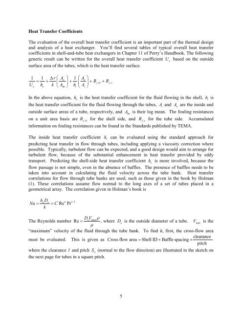
<strong>Heat</strong> Transfer CoefficientsThe evaluation of the overall heat transfer coefficient is an important part of the thermal design<strong>and</strong> analysis of a heat exchanger. You’ll find several tables of typical overall heat transfercoefficients in shell-<strong>and</strong>-tube heat exchangers in Chapter 11 of Perry’s H<strong>and</strong>book. The followinggeneric result can be written for the overall heat transfer coefficient Uobased on the outsidesurface area of the tubes, which is the heat transfer surface.1 1 ∆ r ⎛ A ⎞o1 ⎛ A ⎞o= + ⎜ ⎟+ ⎜ ⎟+ R + RUo ho k ⎝ Alm ⎠ hi ⎝ Ai⎠f ,0 f , iIn the above equation, h ois the heat transfer coefficient for the fluid flowing in the shell, h iisthe heat transfer coefficient for the fluid flowing through the tubes, Ai<strong>and</strong> Aoare the inside <strong>and</strong>outside surface areas of a tube, respectively, <strong>and</strong> Almis their log mean. The fouling resistanceson a unit area basis are Rf ,0for the shell side, <strong>and</strong> Rf , ifor the tube side. Accumulatedinformation on fouling resistances can be found in the St<strong>and</strong>ards published by TEMA.The inside heat transfer coefficient h ican be evaluated using the st<strong>and</strong>ard approach forpredicting heat transfer in flow through tubes, including applying a viscosity correction wherepossible. Typically, turbulent flow can be expected, <strong>and</strong> a good design would aim to arrange forturbulent flow, because of the substantial enhancement in heat transfer provided by eddytransport. Predicting the shell-side heat transfer coefficient h ois more involved, because theflow passage is not simple, even in the absence of baffles. The presence of baffles needs to betaken into account in calculating the fluid velocity across the tube bank. <strong>Heat</strong> transfercorrelations for flow through tube banks are used, such as those given in the book by Holman(1). These correlations assume flow normal to the long axes of a set of tubes placed in ageometrical array. The correlation given in Holman’s book isNuhDko o= =Cn 1/3Re PrDVo maxρThe Reynolds number Re = , where Dois the outside diameter of a tube. Vmaxis theµ“maximum” velocity of the fluid through the tube bank. To find it, first, the cross-flow areaclearancemust be evaluated. This is given as Cross flow area = <strong>Shell</strong> ID × Baffle spacing ×pitchwhere the clearance l <strong>and</strong> pitch Sn(normal to the flow direction) are illustrated in the sketch onthe next page for tubes in a square pitch.5


