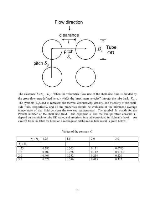
Flow directionpitch SpclearancelpitchS nD o<strong>Tube</strong>ODThe clearance l = Sn − Do. When the volumetric flow rate of the shell-side fluid is divided bythe cross-flow area defined here, it yields the “maximum velocity” through the tube bank, Vmax.The symbols k,ρ , <strong>and</strong> µ represent the thermal conductivity, density, <strong>and</strong> viscosity of the shellsidefluid, respectively, <strong>and</strong> all the properties should be evaluated at the arithmetic averagetemperature of that fluid between the two end temperatures. The symbol Pr st<strong>and</strong>s for thePr<strong>and</strong>tl number of the shell-side fluid. The exponent n <strong>and</strong> the multiplicative constant Cdepend on the pitch to tube OD ratio, <strong>and</strong> are given in a table provided in Holman’s book. Anexcerpt from the table for tubes on a rectangular pitch (in-line tube rows) is given below.Values of the constant CSn/ Do1.25 1.5 2.0 3.0Sp/ Do1.25 0.386 0.305 0.111 0.07031.5 0.407 0.278 0.112 0.07532.0 0.464 0.332 0.254 0.2203.0 0.322 0.396 0.415 0.3176
Values of the constant nSn/ Do1.25 1.5 2.0 3.0Sp/ Do1.25 0.592 0.608 0.704 0.7521.5 0.586 0.620 0.702 0.7442.0 0.570 0.602 0.632 0.6483.0 0.601 0.584 0.581 0.608As an alternative, one can use the procedure outlined in Section 4.5.1 of the book by Mills. Forthe shell-side heat transfer coefficient, the Nusselt number calculated from correlations usingproperties at the arithmetic average of the inlet <strong>and</strong> exit temperatures is usually sufficient.The actual flow patterns are more involved, because the flow entering the shell has to distributeitself into the space in which the tubes are located, <strong>and</strong> then the flow has to turn around eachbaffle. At the exit, the flow again has to converge toward the exit pipe from the shell. Inaddition, corrections need to be applied for leakage around the baffles, for by-pass of tubebundles, <strong>and</strong> other less important non-idealities. As a rough rule of thumb, because of thesevarious corrections, the ideal heat transfer coefficient h ofor flow across the tube bankcalculated using a suitable correlation is multiplied by a conservative correction factor of0.6 in the end.Pressure Drop<strong>Tube</strong>-Side Pressure DropIn designing heat exchangers, pressure drop considerations are usually quite important.Typically, a design constraint might be ∆P ≤ N psi , where the number N is specified, <strong>and</strong> suchconstraints may apply on both the tube side <strong>and</strong> the shell side. Calculation of the tube-sidepressure drop is made by first estimating the (Darcy) friction factor for flow through the tubesfrom the value of the Reynolds number <strong>and</strong> the relative roughness, <strong>and</strong> applying the viscositycorrection we discussed in class. Then, this friction factor is used to evaluate the pressure dropfor flow through the tubes fromL ⎛1P f ⎜ VD ⎝2⎞⎟⎠2∆ =correctedρ ×Number of tube passeswhere L is the length of the tubes, D is the ID of the tubes, ρ is the density of the tube-sidefluid, <strong>and</strong> V is the average flow velocity through a single tube. To this, we must add ∆ Pr, thereturn pressure loss. This accounts for the pressure drop associated with fluid entry into the tubebundle, fluid leaving the bundle, <strong>and</strong> fluid flowing around bends.7