W140 ME Connector PIN assigment.pdf
W140 ME Connector PIN assigment.pdf
W140 ME Connector PIN assigment.pdf

Create successful ePaper yourself
Turn your PDF publications into a flip-book with our unique Google optimized e-Paper software.
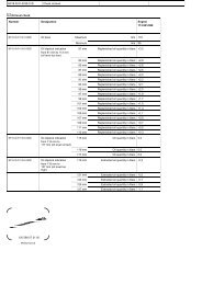
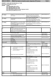
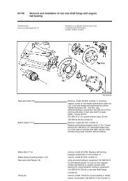
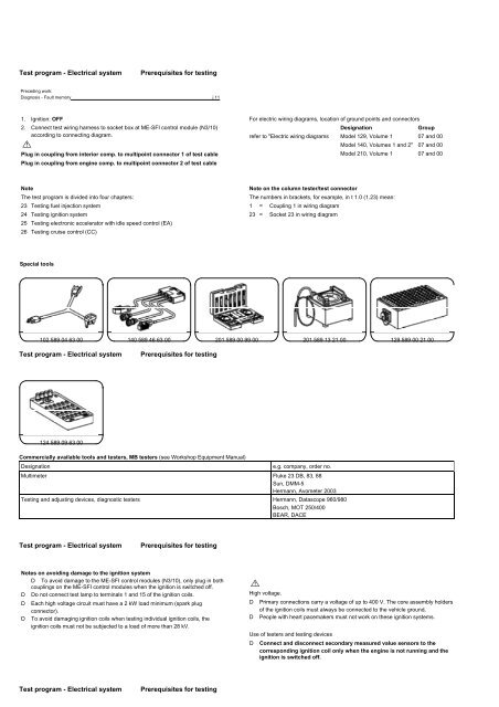
Test program - Electrical systemPrerequisites for testingPreceding work:Diagnosis - Fault memory j 111. Ignition: OFF2. Connect test wiring harness to socket box at <strong>ME</strong>-SFI control module (N3/10)according to connecting diagram.MPlug in coupling from interior comp. to multipoint connector 1 of test cablePlug in coupling from engine comp. to multipoint connector 2 of test cableFor electric wiring diagrams, location of ground points and connectorsDesignationGrouprefer to "Electric wiring diagrams Model 129, Volume 1 07 and 00Model 140, Volumes 1 and 2" 07 and 00Model 210, Volume 1 07 and 00NoteThe test program is divided into four chapters:23 Testing fuel injection system24 Testing ignition system25 Testing electronic accelerator with idle speed control (EA)26 Testing cruise control (CC)Note on the column tester/test connectorThe numbers in brackets, for example, in t 1.0 (1.23) mean:1 = Coupling 1 in wiring diagram23 = Socket 23 in wiring diagramSpecial tools102 589 04 63 00 140 589 46 63 00 201 589 00 99 00 201 589 13 21 00 129 589 00 21 00Test program - Electrical systemPrerequisites for testing124 589 09 63 00Commercially available tools and testers, MB testers (see Workshop Equipment Manual)Designatione.g. company, order no.Multimeter Fluke 23 DB, 83, 88Sun, DMM-5Hermann, Avometer 2003Testing and adjusting devices, diagnostic testers Hermann, Datascope 960/980Bosch, MOT 250/400BEAR, DACETest program - Electrical systemPrerequisites for testingNotes on avoiding damage to the ignition systemD To avoid damage to the <strong>ME</strong>-SFI control modules (N3/10), only plug in bothcouplings on the <strong>ME</strong>-SFI control modules when the ignition is switched off.D Do not connect test lamp to terminals 1 and 15 of the ignition coils.D Each high voltage circuit must have a 2 kW load minimum (spark plugconnector).D To avoid damaging ignition coils when testing individual ignition coils, theignition coils must not be subjected to a load of more than 28 kV.MHigh voltage.D Primary connections carry a voltage of up to 400 V. The core assembly holdersof the ignition coils must always be connected to the vehicle ground.D People with heart pacemakers must not work on these ignition systems.Use of testers and testing devicesD Connect and disconnect secondary measured value sensors to thecorresponding ignition coil only when the engine is not running and theignition is switched off.Test program - Electrical systemPrerequisites for testing
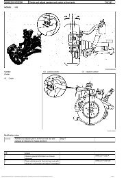
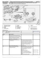
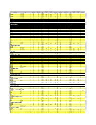
Assignment to coupling "1" interior compartment for <strong>ME</strong>-SFI control module (continuation)Figure 335 Voltage supply (terminal 30) models 129/140 from base moduleVoltage supply (terminal 30) model 210 from relay module36 Voltage supply (terminal 87 E, for EA function)37 -38 Ground W15/1: Electronics ground (footwell, right)39 Ground W15: Common ground (footwell, right)40 Oxygen sensor ground41 Oxygen sensor signal upstream of TWC, right42 Oxygen sensor signal downstream of TWC, right (I only)43 Temperature sensor TWC, right (H only, up to 05/96)44 Voltage supply 5 V for body acceleration sensor, tank pressure sensormodels 140/210 and 129 as of 09/97 I and regeneration monitoringpressure sensor model 129 I up to 08/9745-46 -47 Instrument cluster (warning tone, when 30 km/h limit is exceeded)48 Body acceleration sensor (signal)49 Oxygen sensor signal upstream of TWC, left50 Oxygen sensor signal downstream of TWC, left (I only)P07-6727-5351 Purge monitoring pressure sensor (I only model 129 up to 08/97)Tank pressure sensor (I only models 140/210 and 129 as of 09/97)52 Temperature sensor TWC, left (H only, up to 05/96)53 Ground sensors54 -55 Data link connector (<strong>ME</strong>-SFI injection system)56 Data link connector (engine speed signal)57 AIR relay models 129/140 (I only, u1 as of 12/96 and lowemission D3 as of 07/97)58 Instrument cluster (fuel consumption signal)59 -60 Data bus (CAN) "H"61 Data bus (CAN) "L"Test program - Electrical systemPrerequisites for testingAssignment to coupling "2" engine compartment for <strong>ME</strong>-SFIcontrol module (continuation)Figure 462-63 -64 Intake air temperature sensor (+)65 Pressure sensor (I only)66 Camshaft Hall sensor (signal)67 Mass air flow sensor (signal +)68 Mass air flow sensor (signal -)69 Fuel injection valve: cylinder 370 Fuel injection valve: cylinder 671 Fuel injection valve: cylinder 572 Fuel injection valve: cylinder 173 Ground bridge to plug 9674 Actuator (-)75 Actuator (+)76 Engine coolant temperature sensor (+)77 -78 Crankshaft position sensor (-)79 Knock sensor, right cylinder bank (+)80 Knock sensor, right cylinder bank (-)81 -82 Fuel injection valve: cylinder 883 Ignition coil: cylinder 184 Ignition coil: cylinder 585 Ignition coil: cylinder 486 -87 Sensor ground for: camshaft actuation position sensor, engine coolanttemperature sensor, intake air temperature sensor, pressure sensor (P07-6738-53I only)Test program - Electrical systemPrerequisites for testingAssignment to coupling "2" engine compartment for <strong>ME</strong>-SFIcontrol module (continuation)Figure 588 Voltage supply 5 V pressure sensor (I only)89 Crankshaft position sensor (+)90 Knock sensor, left cylinder bank (+)91 Knock sensor, left cylinder bank (-)92 Secondary air injection relay module model 210 (I only)93 Fuel injection valve: cylinder 494 Ignition coil: cylinder 6,95 Ignition coil: cylinder 896 Ground bridge to plug 7397 Actuator: actual value potentiometer 1 (wiper)98 Actuator: actual value potentiometers 1 and 2 (-)99-102 -103 Fuel injection valve: cylinder 7104-105 -106 Actuator: actual value potentiometers 1 and 2 (+)107 Actuator: actual value potentiometer 2 (wiper)108-110 -111 Electromagnetic actuator, left adjustable camshaft timing112 Fuel injection valve: cylinder 2113 Electromagnetic actuator, right adjustable camshaft timing114 Secondary air injection (AIR) switchover valve (I only, u1as of 12/96 and low emission D3 as of 07/97)115 Ignition coil: cylinder 3116 Ignition coil: cylinder 7117 Ignition coil: cylinder 2P07-6738-53