W124 rear wheel axle shaft & bearing removal.pdf
W124 rear wheel axle shaft & bearing removal.pdf
W124 rear wheel axle shaft & bearing removal.pdf

Create successful ePaper yourself
Turn your PDF publications into a flip-book with our unique Google optimized e-Paper software.
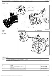
35-130 Removal and installation of <strong>rear</strong> <strong>axle</strong> <strong>shaft</strong> flange with angularball <strong>bearing</strong>Preceding work:Remove, install <strong>wheel</strong>s 40-110.Operation no. of operation texts and work unitsor standard texts and flat rates:35-0260, 35-0261, 35-0262P35-0029-55Rear <strong>axle</strong> <strong>shaft</strong> (37)Remove, install (35-620, number 1). Unscrew,replace, screw on and fasten twelve-point collar nut(12). Lubricate thread and head <strong>bearing</strong> surface.Tightening torque 200 - 240 Nm. Useextractor/pulling-in equipment 140 589 03 61 00 toremove and press in <strong>rear</strong> <strong>axle</strong> <strong>shaft</strong> if it seatstightly. Torque wrench001 589 74 21 00, socket wrench insert 30 mm126 589 02 09 00 (number 2).Brake caliper (111) Remove, install (42-120, number 3).Replace self-locking hexagon bolts (111b). Torquewrench 001 589 66 21 00. Assemble brake hoseor, in the case of vehicles with ASR, electric cableof brake lining wear indicator without twisting.Brake disk (111c)remove, install (42-228). Replace self-lockinghexagon socket bolt (111d) (number 4).Brake shoes of parking brake (112) remove, install (42-530, number 5).Rear <strong>axle</strong> <strong>shaft</strong> flange (10) using extractor/pulling-in equipment 140 589 03 6100 and setbolt section 19, pull out from angularcontactball <strong>bearing</strong> or angular-contact roller<strong>bearing</strong> (8). Using extractor/ pulling-in equipment124 589 05 43 00 pull in <strong>rear</strong> <strong>axle</strong> <strong>shaft</strong> flange(number 6).Circlip (9)remove, install. Check for correct seating in <strong>wheel</strong>carrier. Circlip pliers 126 589 00 37 00 (number 7).
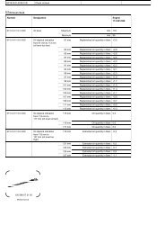
Two-row angular-contact ball <strong>bearing</strong> (8)remove, install. The angular-contact ball <strong>bearing</strong>must contact edge of <strong>wheel</strong> carrier.Extractor/pulling-in equipment 124 589 05 43 00(number 8).Bearing inner race of angular-contact ball <strong>bearing</strong> (8) remove from <strong>rear</strong> <strong>axle</strong> <strong>shaft</strong> flange (numbers 9-11).Puller base equipment 001 589 50 33 00 or001 589 36 33 00, collet chuck 201 589 00 34 00,thrust piece 000 589 03 34 00, open end wrenchWAF 55x65 mm 140 589 00 01 00, open endwrench WAF41 mm 201 589 00 01 00.All parts check for re-use (number 12).Radial and lateral runout of <strong>rear</strong> <strong>axle</strong> <strong>shaft</strong> flange (10) check, nominal value 0.03 mm (number 12).Special tools126 589 02 09 00 140 589 03 61 00 126 589 00 37 00124 589 05 43 00 001 589 50 33 00 201 589 00 34 00000 589 03 34 00 001 589 66 21 00 001 589 74 21 00
140 589 00 01 00 201 589 00 01 00NoteWork can also be carried out on the mounting of the<strong>rear</strong> <strong>axle</strong> <strong>shaft</strong> flange when the <strong>rear</strong> <strong>axle</strong> is installed.7 Wheel carrier8 Two-row angular-contact ball <strong>bearing</strong>9 Circlip10 Rear <strong>axle</strong> <strong>shaft</strong> flange11 Parallel pin12 Twelve-point collar nut37a Rear <strong>axle</strong> <strong>shaft</strong>37b Outer joint race37d Joint hub37e Ball37f Ball cage37g Circlip37k Hose clamp37l Rubber cup sealP35-5512-15Removal, installation1 Remove, install <strong>rear</strong> <strong>axle</strong> <strong>shaft</strong> (35-620).P35-5514-132 If it is tightly seated, use extractor/pulling-inequipment 140 589 03 61 00 to press <strong>rear</strong> <strong>axle</strong> <strong>shaft</strong>out of <strong>rear</strong> <strong>axle</strong> <strong>shaft</strong> flange.P35-5897-13
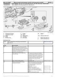
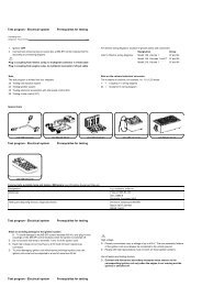
3 Remove, install brake calliper (111) andsuspend on a hook (41-120).Installation noteReplace self-locking hexagon bolt. Install brakehose and, on vehicles with ASR, install electriccable of wear indicator (111h) without twisting.P35-5461-134 Remove, install brake disk (111c) (42-228).Installation noteReplace self-locking hexagon socket bolt (111d).P35-5518-135 Remove, install brake shoes (112) of parkingbrake (42-530).P35-5519-136 Using extractor/pulling-in equipment (010)140 589 03 61 00 with set bolt (010b) and thrustpiece (010a), pull <strong>rear</strong> <strong>axle</strong> <strong>shaft</strong> flange (10) out ofangular-contact ball <strong>bearing</strong> (8) and remove.
7 Wheel carrier8 Two-row angular-contactball <strong>bearing</strong>10 Rear <strong>axle</strong> <strong>shaft</strong> flange010 Extractor/pulling-inequipment010a Thrust piece010b Set bolt010c Threaded bolt010d Support plateP35-5889-33Installation noteUsing extractor/pulling-in equipment (08a, 08b, 08cand 08e) 124 589 05 43 00 draw <strong>rear</strong> <strong>axle</strong> <strong>shaft</strong>flange (10) into two-row angular-contact ball <strong>bearing</strong>(8).MDuring the pulling-in process, the thrust washer124 589 05 43 00, part 03 (08c) must fit tightlyagainst the <strong>bearing</strong> inner race (arrow). In the case ofthe two-row angular-contact ball <strong>bearing</strong>, use thethrust washer side of 45 mm dia. (smaller dia.) andin the case of the two-row angular-contact roller<strong>bearing</strong>, use the thrust washer side of 49 mm dia.(larger dia., T-model only).7 Wheel carrier8 Two-row angular-contactball <strong>bearing</strong>9 Circlip10 Rear <strong>axle</strong> <strong>shaft</strong> flange08a Hexagon bolt with collar nut08b Extractor/pulling-in sleeve08c Thrust washer (small,45 mm dia.)08e Thrust <strong>bearing</strong>P35-5530-35
7 Wheel carrier8 Two-row angular-contactball <strong>bearing</strong>08a Hexagon bolt with collar nut08b Extractor/pulling-in sleeve08d Thrust washer (large)08e Thrust <strong>bearing</strong>P35-5534-359 Screw collet chuck (08f) 201 589 00 34 00 ontobasic puller equipment (08g) 001 589 50 33 00 or001 589 36 33 00 and tighten with 55x65 open endwrench 140 589 00 01 00.P35-5531-1310 Using aluminium jaws clamp <strong>rear</strong> <strong>axle</strong> <strong>shaft</strong>flange in vise. Place thrust piece (010b) 000 589 0334 00 with large diameter on <strong>rear</strong> <strong>axle</strong> <strong>shaft</strong> flange(10).P35-5555-1311 Clamp puller on <strong>bearing</strong> inner race, using puller001 589 50 33 00 or 001 589 36 33 00 and colletchuck 201 589 00 34 00 pull <strong>bearing</strong> inner race off<strong>rear</strong> <strong>axle</strong> <strong>shaft</strong> flange.41 mm open end wrench 201589 00 01 00.P35-5556-13
Testing12 Check all parts to make sure they can be reused.Check radial and lateral runout of <strong>rear</strong> <strong>axle</strong><strong>shaft</strong> flange (nominal value 0.03 mm).Always replace two-row angular-contact ball <strong>bearing</strong>after it has been used once.13 Install in reverse sequence.