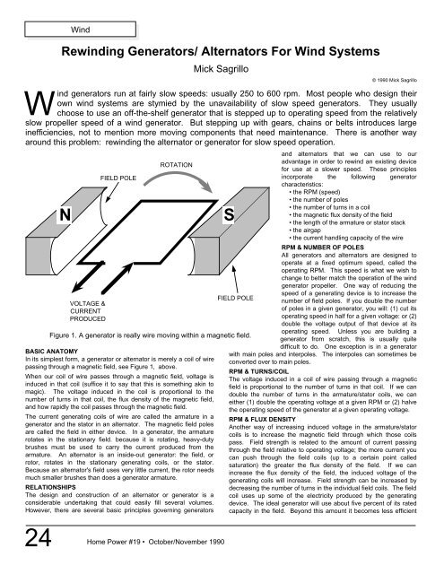
WindRewinding Generators/ <strong>Alternator</strong>s For Wind SystemsMick Sagrillo© 1990 Mick SagrilloWind generators run at fairly slow speeds: usually 250 to 600 rpm. Most people who design theirown wind systems are stymied by the unavailability of slow speed generators. They usuallychoose to use an off-the-shelf generator that is stepped up to operating speed from the relativelyslow propeller speed of a wind generator. But stepping up with gears, chains or belts introduces largeinefficiencies, not to mention more moving <strong>com</strong>ponents that need maintenance. There is another wayaround this problem: rewinding the alternator or generator for slow speed operation.NVOLTAGE &CURRENTPRODUCEDFIELD POLEROTATIONBASIC ANATOMYIn its simplest form, a generator or alternator is merely a coil of wirepassing through a magnetic field, see Figure 1, above.When our coil of wire passes through a magnetic field, voltage isinduced in that coil (suffice it to say that this is something akin tomagic). The voltage induced in the coil is proportional to thenumber of turns in that coil, the flux density of the magnetic field,and how rapidly the coil passes through the magnetic field.The current generating coils of wire are called the armature in agenerator and the stator in an alternator. The magnetic field polesare called the field in either device. In a generator, the armaturerotates in the stationary field. because it is rotating, heavy-dutybrushes must be used to carry the current produced from thearmature. An alternator is an inside-out generator: the field, orrotor, rotates in the stationary generating coils, or the stator.Because an alternator's field uses very little current, the rotor needsmuch smaller brushes than does a generator armature.RELATIONSHIPSThe design and construction of an alternator or generator is aconsiderable undertaking that could easily fill several volumes.However, there are several basic principles governing generatorsSFigure 1. A generator is really wire moving within a magnetic field.and alternators that we can use to ouradvantage in order to rewind an existing devicefor use at a slower speed. These principlesincorporate the following generatorcharacteristics:• the RPM (speed)• the number of poles• the number of turns in a coil• the magnetic flux density of the field• the length of the armature or stator stack• the airgap• the current handling capacity of the wireRPM & NUMBER OF POLESAll generators and alternators are designed tooperate at a fixed optimum speed, called theoperating RPM. This speed is what we wish tochange to better match the operation of the windgenerator propeller. One way of reducing thespeed of a generating device is to increase theFIELD POLEnumber of field poles. If you double the numberof poles in a given generator, you will: (1) cut itsoperating speed in half for a given voltage: or (2)double the voltage output of that device at itsoperating speed. Unless you are building agenerator from scratch, this is usually quitedifficult to do. One exception is in a generatorwith main poles and interpoles. The interpoles can sometimes beconverted over to main poles.RPM & TURNS/COILThe voltage induced in a coil of wire passing through a magneticfield is proportional to the number of turns in that coil. If we candouble the number of turns in the armature/stator coils, we caneither (1) double the operating voltage at a given RPM or (2) halvethe operating speed of the generator at a given operating voltage.RPM & FLUX DENSITYAnother way of increasing induced voltage in the armature/statorcoils is to increase the magnetic field through which those coilspass. Field strength is related to the amount of current passingthrough the field relative to operating voltage; the more current youcan push through the field coils (up to a certain point calledsaturation) the greater the flux density of the field. If we canincrease the flux density of the field, the induced voltage of thegenerating coils will increase. Field strength can be increased bydecreasing the number of turns in the individual field coils. The fieldcoil uses up some of the electricity produced by the generatingdevice. The ideal generator will use about five percent of its ratedcapacity in the field. Beyond this amount it be<strong>com</strong>es less efficient24 Home Power #19 • October/November 1990
to the point where saturation is reached and the field be<strong>com</strong>esparasitic. Field coils are usually connected in series in a generatingdevice. One easy way to increase the current draw in a set of fieldcoils without rewinding them is to divide them in parallel. Thisseries/parallel arrangement still allows for north and south orientedpoles.INDUCED VOLTAGE AND ARMATURE/STATOR LENGTHYet another way of increasing induced voltage is by making thecoils that pass through the magnetic field longer. Doubling thearmature/stator stack results in a doubling of induced voltage.AIRGAPThe amount of space between the field coils and armature/statorcoils is known as the airgap. The airgap is necessary to prevent thecoils from rubbing on the fields after both have expanded due to theheat given off by the electrical generating process. However, theairgap works against the flux density of the field: the greater theairgap, the greater the current needed by the field to over<strong>com</strong>e theairgap. Most alternators and generators have much larger airgapsthan necessary due to sloppy construction. The airgap can belessened by shimming the field poles with ferrous shimstock. Theonly way to do this is on a trial & error basis in small increments.WIRE AMPACITYThe current output of the armature/stator is entirely dependent uponthe current carrying capacity, or ampacity, of the wire used.Ampacity is related to wire size. Comparing relative wire sizes canbe ac<strong>com</strong>plished by <strong>com</strong>paring the wire's circular area (called circ.mils), unit weight, unit length, or unit resistance. The following chartFIGURE 2: COPPER WIRE TABLEWire Circular Pounds/ Feet/ Ohms/Guage Mils 1000 feet Pound 1000 feet10 10380.0 31.430 31.82 0.998911 8234.0 24.920 40.13 1.260012 6530.0 19.770 50.58 1.588013 5178.0 15.680 63.77 2.003014 4107.0 12.430 80.45 2.525015 3257.0 9.858 101.40 3.184016 2583.0 7.818 127.90 4.016017 2048.0 6.200 161.30 5.064018 1624.0 4.917 203.40 6.385019 1288.0 3.899 256.50 8.051020 1022.0 3.092 323.40 10.150021 810.1 2.452 407.80 12.800022 642.4 1.945 514.10 16.140023 509.5 1.542 648.50 20.360024 404.0 1.223 817.70 25.6700lists these relationships for wire sizes used in generators &alternators: Note that half sizes exist for most wire gauges but inthe interest of clarity are not listed.We have been talking about doubling the voltage or halving theRPM of a generating device by doubling the number of turns of wirein the coils. These coils fit into slots on the armature or stator. Theslots have a given physical size that cannot be changed.Obviously, you can't fit more wire into a slot than it was designed forunless you use a lighter gauge wire. This is where the Copper WireTable <strong>com</strong>es into use. If you wish to double the number of turns in acoil, you must halve the size of the wire. This corresponds to threesteps down on the wire chart. For example, say we have armatureHome Power #19 • October/November 1990Windcoils with 7 turns of #15 wire. The circ. mil area is 3.257. One half ofthis would be about 1.6. This area is equal to #18 wire. The new coilsmade from 14 turns of #18 wire would fit into the existing slots.Note, however, that by halving the size of the wire, you also halve thecurrent carrying capacity of that wire. There is no free lunch! If youwant a slower speed, you have to give up something. This new wiresize will limit the power output of the rewound generator.FER INSTANCE…Let's say that we have a 1200 RPM, 32 VDC motor that we want tomake into a wind generator, (DC motors & generators are more or lessinterchangeable). The motor draws 30 amps. We want it to run at amaximum speed of 300 RPM, and we'd like to power our hot waterheater with the wind generator. The heating elements in the waterheater are rated at 120 volts. We take the motor apart and discoverthat it has two main poles and two interpoles of the same physical sizeas the main poles. The wire in the interpole coils is finer than that of themain poles. We have pulled the armature apart and find that we havecoils made of #10 wire with 4 turns/coil. What to do? Let's begin withthe interpoles. If we rewind them to the same number of poles with thesame gauge wire as the main poles, we have just doubled the numberof poles in the generator. This has the effect of cutting the speed of thegenerator to 600 RPM, but still at 32 VDC. In order to get the speeddown to 300 RPM, we need to double the turns of wire in the armaturecoils, from 4 to 8. Wire size is reduced from #10 to #13. But we're stillat 32VDC! If we halve the wire size again, we're up to 64 VDC. onemore time and we finally get to 128VDC, close enough! But we've takentwo more jumps in wire size, from #13 to #16 to #19, and doubled theturns twice, from 8 to 16 to 32. Our final armature coils would then be32 turns of #19 wire. What kind of current can we expect out of thisgenerator? Doubling the field poles has no effect (in this case) oncurrent. However, going to smaller wire gauge in the armature does.Going from #10 to #13 cut our current production from 30 amps to 15amps. Two more jumps to #19 wire cuts our current output to 3 3/4amps. Our wind generator will put out 4 amps intermittently at 120 voltswith a top propeller speed of 300 RPM. This same process can beused in reverse to rewind a generator for lower voltage & higher current.ANOTHER APPROACHWe have several old 12 volt, 100 amp Chrysler alternators in the scrapheap. We need an alternator for our hydro plant or wind genny to putout 24 VDC to match the PV array and inverter. New 24 volt alternatorscost $400! What to do?Car alternators possess several interesting features that can be used toour advantage. First, since we have several of these things, we haveseveral lamination stacks at our disposal. If we take two of these cores,strip the wire and pop the rivets out, we can bolt them back together forrewinding. Since the lamination stack is doubled in size, we justdoubled our voltage, from 12 volts to 24, without changing wire size.The same thing can be done with the rotor by merely feeding 24 voltsinto it. We'd need to use a 3-phase bridge rectifier in place of the usualvoltage regulator. We can then proceed to rewind with different wiregauges to meet the RPM specs of our hydro or wind plant.FOR THE LIBRARYAnyone wishing more detailed information on rewinding can order thefollowing republished out-of-print books from Lindsay Publications, POB12, Bradley IL 60915. Both books cost $11.90 postpaid. Autopower, byS.W. Duncan, 1935 (Catalog #4791) LeJay Manual, by Lawrence D.Leach, 1945 (Catalog #20013)ACCESSMick Sagrillo, Lake Michigan Wind & Sun, 3971 E. Bluebird Rd.Forestville, WI 54213 • 414-837-2267.25