
Create successful ePaper yourself
Turn your PDF publications into a flip-book with our unique Google optimized e-Paper software.
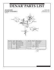
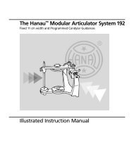
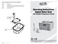
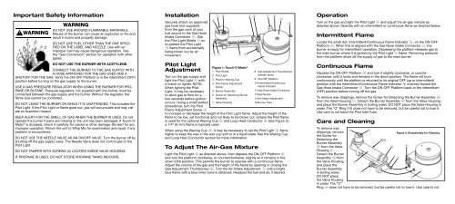
Important Safety InformationWarningDo not use around flammable materials.WARNING Misuse of the burner can cause an explosion or fire andresult in burns and property damage.Do not use fuel other than the one specifiedon the label and nozzle. Use with animproper fuel may cause dangerous operation. Seethe “Gas Conversion” section for operation with othergases.Do not use the burner with acetylene.Connect the burner to the gas supply witha hose approved for the gas used and ashutoff for the gas. Verify the ON-OFF Platform is in the intermittent (OFF)position before turning on the gas supply to the burner.Use a gas pressure regulator when using the burner for propaneor butane. Pressure regulators, not supplied with the burner, must beconnected between the gas supply and the burner. Without the regulator, theflame size cannot be controlled.Do not leave the burner on while it is unattended. This includes thePilot Light. If the Pilot Light or flame goes out, gas will accumulate and may createan explosion hazard.Keep alert for the smell of gas when the burner is used. Do notoperate the burner if parts are missing or the unit has been damaged. If <strong>Touch</strong>-O-<strong>Matic</strong> ® is dropped, check it carefully for cracks or other damage. Be alert for anyimproper operation. Return the unit to <strong>Whip</strong> <strong>Mix</strong> for examination and repair if anyproblem is encountered.Do not use the needle valve as an On/Off valve. Turn the burner off byshutting off the gas supply valve. The Needle Valve does not control gas to thePilot Light.Do not tamper with screws (4) located inside valve housing.If propane is used, do not store propane tanks indoors.InstallationSecurely attach an approvedgas hose (not supplied)from the gas cock of yourfuel source to the Gas HoseIntake Connector -. Slipthe Pilot Light Shield 1 onto protect the Pilot Light2 flame from accidentallybeing blown out by airmovement.Pilot LightAdjustmentTurn on the gas supply andlight the Pilot Light 2 witha match or lighter. NOTE:When lighting the PilotLight, it may be necessaryto allow gas to flow for afew seconds before ignitionoccurs. Using a small slottedscrewdriver, turn the PilotFlame Adjustment Screw 41 r q = - 09824 3 5 6Figure 1: <strong>Touch</strong>-O-<strong>Matic</strong> ®1 Pilot Shield2 Pilot Light3 Post for Waxing Cup4 Pilot Flame AdjustmentScrew5 Burner Assembly6 Screw for Detaching BurnerAssembly7 Valve Housingto increase or decrease the height of the Pilot Light flame. Adjust the height of theflame to be low, yet functional and not likely to be blown out. Unless the Pilot flameis used for the optional Waxing Cup t and Loop Heat Conductor y (see Figure 3),a 1/4” (6 mm) flame is typically used.When using the Waxing Cup t, it may be necessary to set the Pilot Light 2 flamehigher to keep the wax in the wax cup soft or in a liquid state. See the Waxing Cupand Loop Heat Conductor section for more information.To Adjust The Air-Gas <strong>Mix</strong>tureLight the Pilot Light 2 as directed above, then depress the ON-OFF Platform 9and turn the platform clockwise, or counterclockwise, slightly so it remains in thedown (ON) position. This permits the burner to operate with a continuous flame.Adjust the volume of the gas and the height of the flame by opening or closing theGas Adjustment Thumbscrew 8. Turn the Air-Intake Adjustment q until a brightblue flame with a blue inner cone is obtained. Readjust the fuel and air, if desired.78 Gas Adjustment Thumbscrew(needle valve)9 ON-OFF Platform10 Intermittent/ContinuousFlame Indicator11 Gas Hose Intake Connector12 Gas Nozzle13 Air-Intake Adjustment16 Burner TubeOperationTurn on the gas and light the Pilot Light 2 and adjust the air-gas mixture asdirected above. Operate with an intermittent or continuous flame as directed below.Intermittent FlameLocate the small dot, Intermittent/Continuous Flame Indicator 0, on the ON-OFFPlatform 9. When this is aligned with the Gas Hose Intake Connector -, theburner is ready for intermittent operation. Depressing the platform releases gas tothe main burner where it is ignited by the Pilot Light 2 flame. Removing pressurefrom the platform shuts off the supply of gas to the main burner.Continuous FlameDepress the ON-OFF Platform 9 and turn it slightly clockwise, or counterclockwise,until it locks and remains in the down position. The flame will burncontinuously until the platform is returned to its original OFF (up or intermittent)position with the Intermittent/Continuous Flame Indicator 0 oriented toward theGas Hose Intake Connector -. Turn the ON-OFF Platform back to the intermittent(OFF) position before turning off the gas.To remove wax drippings, remove the Screw for Detaching the Burner Assembly 6from the Valve Housing 7. Detach the Burner Assembly 5 from the Valve Housing,and place the Burner Assembly in boiling water. DO NOT place the Valve Housing inwater. The “O” Ring (14) does not have to be removed, but be careful not to lose it.Use care to not bend the Pilot Inlet Tube.Care and CleaningTo remove wax2drippings, removethe Screw forrFigure 2: Disassembly for CleaningDetaching theBoilBurner Assembly6 from the ValveHousing 7.Detach the BurnerAssembly 5 fromqe w=the Valve Housing,and place the5Burner Assemblyin boiling water.6DO NOT placethe Valve Housing7in water. The “O”Ring w does not have to be removed, but be careful not to lose it. Use care to not