DESIGN PHILOSOPHY TABLE OF CONTENTS PAGE I. SCOPE 2 II ...
DESIGN PHILOSOPHY TABLE OF CONTENTS PAGE I. SCOPE 2 II ...
DESIGN PHILOSOPHY TABLE OF CONTENTS PAGE I. SCOPE 2 II ...

You also want an ePaper? Increase the reach of your titles
YUMPU automatically turns print PDFs into web optimized ePapers that Google loves.
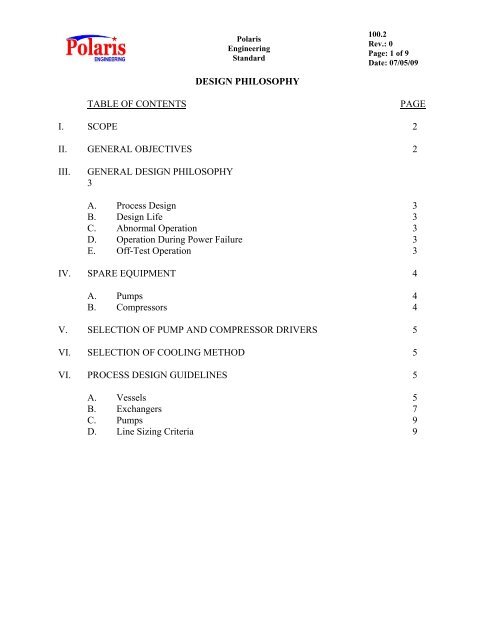
PolarisEngineeringStandard100.2Rev.: 0Page: 1 of 9Date: 07/05/09<strong>DESIGN</strong> <strong>PHILOSOPHY</strong><strong>TABLE</strong> <strong>OF</strong> <strong>CONTENTS</strong><strong>PAGE</strong>I. <strong>SCOPE</strong> 2<strong>II</strong>. GENERAL OBJECTIVES 2<strong>II</strong>I.GENERAL <strong>DESIGN</strong> <strong>PHILOSOPHY</strong>3A. Process Design 3B. Design Life 3C. Abnormal Operation 3D. Operation During Power Failure 3E. Off-Test Operation 3IV. SPARE EQUIPMENT 4A. Pumps 4B. Compressors 4V. SELECTION <strong>OF</strong> PUMP AND COMPRESSOR DRIVERS 5VI. SELECTION <strong>OF</strong> COOLING METHOD 5VI. PROCESS <strong>DESIGN</strong> GUIDELINES 5A. Vessels 5B. Exchangers 7C. Pumps 9D. Line Sizing Criteria 9
PolarisEngineeringStandard100.2Rev.: 0Page: 2 of 9<strong>DESIGN</strong> <strong>PHILOSOPHY</strong>I. <strong>SCOPE</strong>This Standard outlines the design philosophy to be followed for refinery, chemical, andproduction facilities.Where conflicts exist between this Engineering Standard and other POLARISEngineering Standards and/or applicable codes or regulations, the more stringentrequirement shall govern. All conflicts shall be brought to Client’s attention forresolution. Client shall be the sole arbiter of any conflicts.<strong>II</strong>.GENERAL OBJECTIVESIt is the Client's objective that all facilities be provided at minimum cost while satisfyingrequirements for operability and safety as stated herein. No design, regardless of cost, ispermitted which reduces safety of operation below the Client’s or industry standards,whichever is more stringent.Quality of materials, equipment and workmanship are not to be sacrificed to obtain lowerinvestment. Rather, savings shall be obtained by elimination of unnecessary equipment,compact layout to reduce materials, sound engineering design, and avoidance ofunjustified surplus capacity. Incremental investments above this minimum will beapproved only when they satisfy the economic criteria for the project.It is the Client’s intent to operate all process facilities continuously for a minimum ofthree years without shutdown for inspection and maintenance; therefore, the design,materials, and equipment shall be of proven reliability to provide this objective.To assist in attaining these general objectives, the following design guidelines shall befollowed by the Contractor unless he can demonstrate to the Client a less costly and moreefficient way to accomplish these same objectives. Contractor must have the Client'sprior approval in writing before proceeding in these cases.<strong>II</strong>I.GENERAL <strong>DESIGN</strong> <strong>PHILOSOPHY</strong>A. Process DesignIn general, the process design shall provide the capacity, product quality andyields specified by Client. No reserve for future potential capacity or flexibility isdesired unless otherwise specified.B. Design LifeExcept where more stringent requirements are specified by POLARIS or industrystandards, equipment and piping shall be designed for twenty years operating life.
PolarisEngineeringStandard100.2Rev.: 0Page: 3 of 9Where corrosion rates are specified by Client, they shall be used to determinecorrosion allowances that are to be built into the equipment. Where corrosionrates are not specified, corrosion rates generally accepted in the petroleumindustry shall be used, and the Contractor shall specify the corrosion rate orcorrosion allowance he has used for each limiting material on each piece ofequipment. Corrosion allowances specified in these standards shall be consideredthe minimum acceptable values.C. Abnormal OperationPlant design, including equipment capacities and necessary piping shall providefor start-up, shutdown, fail safe operation on power or cooling water outage, offtestoperation, and other unusual but inevitable operating conditions or upsets.D. Operation During Power FailureIt is not intended that the processing facilities will operate during a completepower failure. However, the facilities shall be designed and supplied with enoughsteam drivers, alarms, warning devices, automatic steam cut-ins, and the like sothat in the event of a complete power failure, all processing facilities can be shutdown by a minimum operating staff in an orderly manner without damage to anyfacilities or equipment.E. Off-Test OperationProcess units shall be designed to internally recycle any off-test or “slop” stockswhenever practical. If necessary, off-test pumping and control facilities shall beprovided to permit disposal of off-test and other "slop" stocks to tankage. Off-testconnections shall be centralized (preferably at the Battery limit) to form a slopmanifold where possible.IV.SPARE EQUIPMENTA. PumpsIn general, all pumps except those considered non-critical to process operationsby Client are to be spared.1. Where pumping duty is handled by a single pump, the spare pumps shallbe of equivalent (100%) capacity. Where multiple pumps are required forthe design duty, the spare pump shall be equivalent in capacity to one suchpump (50%, 33%, etc.).2. Common spares will be considered with Client’s approval when thepumping services spared by the common pump are streams of similarcharacteristics.
PolarisEngineeringStandard100.2Rev.: 0Page: 4 of 93. Pumps in non-critical service, such as basement sump pumps and certainchemical injection pumps are generally not spared. The Client shall verifywhich services are considered non-critical.4. In critical services the main pump shall be steam turbine driven and thespare pumps shall have motor drivers. The motor driver shall be providedwith an auto-start system. Critical services, such as lube oil, shall be asdefined by the Client.B. CompressorsAll process compressors shall be spared unless approved by Client. In general, allutility compressors except those considered non-critical to process operations byClient are to be spared. Consideration shall be given to providing the requiredcapacity in two or more machines for a particular service when:1. Loss of total compressor capacity would endanger operations, poisoncatalyst, and the like.2. Processing can continue at a reduced rate without appreciable affect onother processing facilities or without reducing the throughput of the entirerefining facility.3. The incremental cost for the multiple units over the single machine canreasonably be justified on an insurance basis or by continuation ofoperation at a reduced rate.V. SELECTION <strong>OF</strong> PUMP AND COMPRESSOR DRIVERSPumps and compressors shall generally be motor driven except where specifically statedotherwise. However, Contractor may utilize steam turbine drivers, with Clients approval,where required to achieve economic steam balance, and where reduced operating costswarrant the additional investment within the criteria established by Client for the project.VI.PROCESS <strong>DESIGN</strong> GUIDELINESThe following are selected process design guidelines that are to be used by the Contractoras indicated. These criteria represent Client’s minimum requirements, except wherestated in Project Design Specifications or Basic Engineering Design Data and are notintended to supercede Contractor’s customary design practices. Other process designcriteria will be per the Contractor’s standard practices. Contractor will identify anysignificant conflicts and bring them to Client’s attention for review and approval.Contractor shall provide Client with access to his standard practices for spot checks toensure conformance of the Contractor to these standards.A. Vessels
PolarisEngineeringStandard100.2Rev.: 0Page: 5 of 91. Towers/Drums Design Pressurea. Non-liquid Full Vessels1) Operating pressure x 1.10 or + 25 psi (whichever is greater)2) Unless otherwise specified, all vessels to be designed forfull vacuum at 300ºFb. Liquid Full VesselsSame as above but calculate as shut-in pressure ÷ 0.9. Use this fordesign if higher than a.1) above. This will avoid lifting of reliefvalve on major liquid full vessels when exposed to pump shut-inconditions.2. Towers/Drums Design Temperatures3. Traysa. Maximum Operating Temperature + 50 ºF Min.b. Unless otherwise specified, 300 ºF @ full vacuumc. Minimum design temperature = 300ºF at design pressure.d. Unless otherwise specifed, use 650 ºF minimum designtemperature for Carbon Steel unless this requires a higher flangerating.a. Maximum percent flood shall be 80% based on using conventionaltrays.b. Design for turndown to 40% of design rates.c. Trays in foaming and high pressure services are to be sized byusing appropriate system factors. Examples of typical systemfactors are:- Amine Absorber 0.80- Amine Regenerator 0.85- Hydrocarbon Absorber 0.75- Gas Plant Stripper 0.85- Sour Water Stripper 0.75For high pressure fractionation, with vapor densities of 1.8 lb/ft 3 orhigher, use the following:
PolarisEngineeringStandard100.2Rev.: 0Page: 6 of 9- System factor = 1.21 / d v 0.32 , where d v is vapor density, lb/ft 3d. Minimum spacing between trays shall be 24” unless approved byClient.4. Vessel SizingHorizontal DrumHydrocarbon residence time(HLL-LLL)Low Liquid Level (LLL)High Liquid Level (HLL)Water BootWater residence time (HLL-LLL)Low Liquid Level (LLL)High Liquid Level (HLL)5 minutes minimumMinimum 1’-0” above bottomor as required for watersettlingMaximum 1’-0” below top oras required per vapor / liquidseparation criteria4 minutesMinimum 1’-0” above bottomtangent lineMaximum 1’-0” below toptangent lineVapor Flow AreaDroplet / particle size for separation 150 – 500 microns withdemister pad300 microns maximum withoutdemister pad150 microns maximum forCompressor Suction andInterstage DrumsChimney Tray residence timeSteam Generation QualityGreater of:a) 3 minutes on net productplus reflux.b) 1 minute on totalliquids(including pumparound)Remove 100% of all entraineddroplets 8 microns and larger.Maximum 20 ppb Na inproduct steam. Chevron typeseparators external to steamdrum are required.
PolarisEngineeringStandard100.2Rev.: 0Page: 7 of 9B. Exchangers1. Exchanger Design Pressurea. Pumped systems:1) Design pressure = shut-in ÷ 0.952) When protected by a common relief valve with a vesselcalculate as shut-in pressure ÷ 0.9.b. Reboilers, overhead condensers, feed exchangers, etc. Designpressure = System PSV setting ± pressure drop ± static headeffects. In general, tower overhead condenser and receiver designpressure = column design pressure. Reboiler design pressure =column design pressure + the greater of tray pressure drop or 5 psi.c. In all cases, the design pressure of the lower pressure side shouldbe set so that the low pressure side test pressure is equal to orgreater than the high pressure side design pressure.2. Exchanger Design Temperaturesa. Maximum Operating Temperature + 50 ºF Min.b. Unless otherwise specified, 300 ºF @ full vacuumc. Minimum design temperature = 300ºF at design pressure.d. Unless otherwise specifed, use 650 ºF minimum designtemperature for Carbon Steel unless this requires a higher flangerating.3. Fouling Factorsa. In the absence of specific licensor or Client supplied data, thetypical fouling resistances in TEMA shall be used as a guideline.It is preferable to use job specific fouling resistances approved byClient.Unless approved by Client the following minimum fouling factorsshall be used:1) For process streams:a) 0.002 ft 2 - hr-°F/BTU for Naphtha and lighter.
PolarisEngineeringStandard100.2Rev.: 0Page: 8 of 9C. Pumps4. Design Marginsb) 0.003 ft 2 - hr-°F/BTU for distillate and heavier.2) For steam: 0.0005 ft 2 - hr-°F/BTU.3) For temperate water: 0.001 ft 2 - hr-°F/BTU4) For the air side of air coolers: 0.002 ft 2 - hr-°F/BTU.In general a minimum design margin (flows and duties) of 1.1 shall beused for all heat exchange services. For tower overhead condensers andpump-arounds the margin shall be 1.2.Good engineering judgement must be used to determine if other serviceswarrant higher design margins, due to such factors as feedstockvariability, future catalyst improvement, etc.1. Datum for NPSHA calculations shall be bottom tangent (vertical vessels)or bottom invert (horizontal vessels).2. Unless otherwise specified, NPSHA reported on data sheet shall be NPSH(calculated) – 1 foot.3. Allow for permanent suction strainer 50% plugged or 0.3 psi delta P,whichever is greater.4. Shut-in Pressure: Pump shut in pressure is defined as shut in head plusmaximum suction pressure (assume shut in head is equal to 1.25 timesdesign head if a pump curve is not available). Maximum suction pressureis source PSV set pressure ± static head ± pressure drop effects.5. Reflux and pump-around pumps should be designed with 20% excess flowcapability. All other pumps should be designed with 10% excess flowcapability.D. Line Sizing CriteriaApply 20% margin to friction factor. Use the following guidelines for pressuredrop and velocity.PressureDropVelocityFt / SecPSI / 100 ftBoiling liquids (at equilibrium) to pump 0.05 – 0.25 1 – 4Sub-cooled liquids (40º F below bubble point) 0.2 – 1.0 1 – 8
PolarisEngineeringStandard100.2Rev.: 0Page: 9 of 9PressureDropPSI / 100 ftVelocityFt / Secto pump suctionCooling water to pump suction 0.2 – 1.0 1 – 8Pump discharge & liquids under pressure 1.0 – 2.0 5 – 10(Note 1)Cooling water at pump discharge 0.5 – 2.0 5 – 12Differential pressure liquids - 15 Max.Process GasesVacuum (Note 2) 0.02 – 0.3 300 Max.Atmospheric +/- (Note 2) 0.1 – 0.5 150 Max.Pressure (>50 psig) 0.5 – 1.0 100 Max.Steam50 psig headers & laterals 0.1 – 0.25 150 Max.300 / 600 psig - headers 0.5 – 1.5 250 Max.- laterals 0.5 – 2.5 250 Max.- Vacuum (Note 2) Based onavailabledelta P300 Max.Two Phase Flow (Notes 3 & 4) 4 Max. 100/SQRT (mixdensity) Max.Lean Amine - 5 Max.Rich Amine - < 5 Max.Sour Water - 5 Max.Notes:(1) For offsite rundown lines, keep pressure drop around 0.5 – 1.0 psi/100ft.(2) For critical services such as turbine exhaust and compressor suction sizeline such that available delta P/calculated delta P ≥ 1.20.(3) For thermosyphon reboilers available/calculated pressure drop should be2/1 when using average mixed phase density.(4) For two phase systems with straight vertical runs in excess of 5 diameters,check for slug flow.