CONCRETE CONSTRUCTION TABLE OF CONTENTS PAGE I ...
CONCRETE CONSTRUCTION TABLE OF CONTENTS PAGE I ...
CONCRETE CONSTRUCTION TABLE OF CONTENTS PAGE I ...
Create successful ePaper yourself
Turn your PDF publications into a flip-book with our unique Google optimized e-Paper software.
Polaris<br />
Engineering<br />
Standard<br />
430.1<br />
Rev.: 0<br />
Page: 1 of 9<br />
Date: 07/07/09<br />
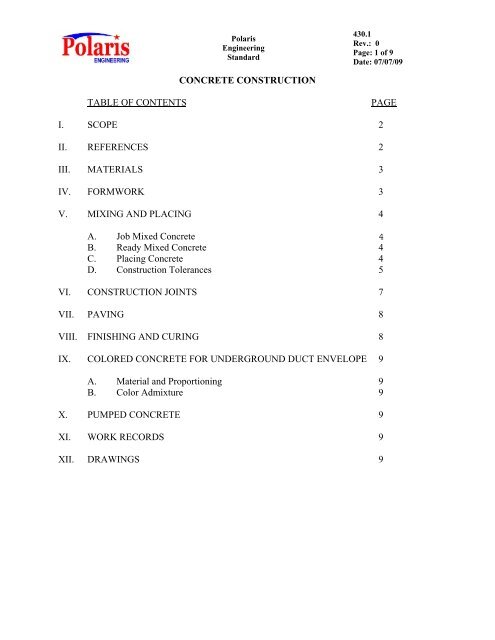
<strong>CONCRETE</strong> <strong>CONSTRUCTION</strong><br />
<strong>TABLE</strong> <strong>OF</strong> <strong>CONTENTS</strong><br />
<strong>PAGE</strong><br />
I. SCOPE 2<br />
II. REFERENCES 2<br />
III. MATERIALS 3<br />
IV. FORMWORK 3<br />
V. MIXING AND PLACING 4<br />
A. Job Mixed Concrete 4<br />
B. Ready Mixed Concrete 4<br />
C. Placing Concrete 4<br />
D. Construction Tolerances 5<br />
VI. <strong>CONSTRUCTION</strong> JOINTS 7<br />
VII. PAVING 8<br />
VIII. FINISHING AND CURING 8<br />
IX. COLORED <strong>CONCRETE</strong> FOR UNDERGROUND DUCT ENVELOPE 9<br />
A. Material and Proportioning 9<br />
B. Color Admixture 9<br />
X. PUMPED <strong>CONCRETE</strong> 9<br />
XI. WORK RECORDS 9<br />
XII. DRAWINGS 9
Polaris<br />
Engineering<br />
Standard<br />
430.1<br />
Rev.: 0<br />
Page: 2 of 9<br />
Date: 07/07/09<br />
<strong>CONCRETE</strong> <strong>CONSTRUCTION</strong><br />
I. SCOPE<br />
This Standard covers requirements for construction of concrete structures and<br />
foundations.<br />
Where conflicts exist between this Engineering Standard and other POLARIS<br />
Engineering Standards and/or applicable codes or regulations, the more stringent<br />
requirement shall govern. All conflicts shall be brought to Client and/or Polaris<br />
Engineering’s attention for resolution. Client and/or Polaris Engineering shall be the sole<br />
arbiter of any conflicts.<br />
II.<br />
REFERENCES<br />
This POLARIS Standard is to be used in conjunction with the latest revision of the<br />
standards and codes listed below, unless specifically noted. The terminology "latest<br />
revision" shall be interpreted as the revision in effect at the time of contract award. This<br />
POLARIS Standard may reference specific sections of some of these codes and<br />
standards. The revision of the codes and standards being referenced is noted below in<br />
parenthesis. This information is provided to identify the subject matter being referenced.<br />
Changes or exceptions made to the referenced code or standard shall apply to later<br />
revisions as applicable.<br />
A. POLARIS Engineering Standards:<br />
1. 410.1 Concrete Roads and Paving<br />
2. 430.2 Concrete Materials and Testing<br />
3. 430.3 Concrete Reinforcing<br />
B. American Concrete Institute (ACI) Codes and Standards:<br />
1. 117 Standard Tolerances For Concrete Construction and<br />
Materials (1990)<br />
2. 304R Guide for Measuring, Mixing, Transporting and Placing<br />
Concrete (2000)<br />
3. 305R Hot Weather Concreting (1999)<br />
4. 318 Building Code Requirements for Structural Concrete<br />
(1999)<br />
5. 325.9R Guide for Construction of Concrete Pavements and<br />
Concrete Bases (1991)
Polaris<br />
Engineering<br />
Standard<br />
430.1<br />
Rev.: 0<br />
Page: 3 of 9<br />
Date: 07/07/09<br />
6. 347 Guide To Formwork For Concrete (2001)<br />
C. American Society For Testing Materials (ASTM) Standards:<br />
1. C33 Standard Specification for Concrete Aggregates (2001)<br />
2. C94 Standard Specification for Ready-Mixed Concrete (2000)<br />
3. C150 Standard Specification for Portland Cement (2000)<br />
III.<br />
MATERIALS<br />
A. Concrete materials and concrete reinforcing are to be in accordance with design<br />
drawings and the reference Standards stated above.<br />
B. Air entraining or super plasticizer admixtures shall be provided in all concrete, in<br />
accordance with POLARIS Engineering Standard 430.2. Client and/or Polaris<br />
Engineering shall approve choice of admixture to be used.<br />
C. Other admixtures shall not be used without written approval from the Client<br />
and/or Polaris Engineering.<br />
IV.<br />
FORMWORK<br />
A. Concrete forms shall conform to shapes, lines and dimensions of the members as<br />
shown on design drawings. They are to be sufficiently tight to prevent leakage of<br />
mortar, and be properly braced or tied together to maintain position and shape.<br />
B. Provide 2 inches minimum clearance from top and sides of foundation to all<br />
reinforcing bars (including ties) and 3 inches minimum clearance for bottom bars<br />
from bottom of foundation.<br />
C. Remove forms in such a manner as not to impair the safety and serviceability of<br />
the structure. Formwork for columns, walls, sides of beams, and other parts not<br />
supporting the weight of the concrete may be removed as soon as the concrete has<br />
hardened sufficiently to resist damage from removal operations. In no case shall<br />
supporting forms or shoring be removed until members have acquired sufficient<br />
strength to support their weight and imposed loads safely. Sufficient strength for<br />
beams, slabs and other items requiring support is defined as when test cylinders,<br />
field cured along with the concrete they represent, have reached 2/3 of the<br />
specified concrete strength.<br />
D. The design and construction of the formwork shall be in accordance with ACI<br />
347. This responsibility shall rest with the Construction Contractor or Concrete<br />
Subcontractor.
Polaris<br />
Engineering<br />
Standard<br />
430.1<br />
Rev.: 0<br />
Page: 4 of 9<br />
Date: 07/07/09<br />
V. MIXING AND PLACING<br />
A. Job-Mixed Concrete<br />
1. Job-mixed concrete shall be in accordance with ACI 304R.<br />
2. Rotate the mixer at a speed recommended by the mixer manufacturer.<br />
Continue mixing for at least 1-1/2 minutes after all materials are in the<br />
mixer.<br />
3. Mix all concrete until there is a uniform distribution of the materials and<br />
discharge completely before recharging the mixer.<br />
B. Ready-Mixed Concrete<br />
Mix and deliver Ready-mixed concrete in accordance with ASTM C94.<br />
C. Placing Concrete<br />
1. Deposit concrete as near as practical to its final position to avoid<br />
segregation of aggregates due to rehandling or flowing. The concrete<br />
must be plastic at all times and flow readily into the spaces between<br />
reinforcing bars. Water in excess of approved batch quantities shall not be<br />
added for this purpose; however, appropriate admixtures approved by the<br />
Client and/or Polaris Engineering may be used to improve flow.<br />
2. After concrete placement has started, continue operation until the section<br />
is completed except as prohibited or permitted by Section VI.<br />
3. Do not drop concrete vertically more than eight feet. Use drop chutes for<br />
higher lifts. The chute shall have a diameter of at least eight times the<br />
maximum aggregate size and shall be positioned so that the concrete will<br />
drop vertically.<br />
4. Do not start placing concrete in supported elements (beams or slabs) until<br />
the concrete previously placed in columns or walls is no longer plastic and<br />
has been in place at least two hours.<br />
5. All concrete shall be thoroughly consolidated by suitable means during<br />
placement, and shall be thoroughly worked around the reinforcement and<br />
embedded items and into the corners of the forms.<br />
6. Install all embedded items such as anchor bolts, sleeves, inserts,<br />
equipment bed and slide plates in their correct location and secure against<br />
displacement.
Polaris<br />
Engineering<br />
Standard<br />
430.1<br />
Rev.: 0<br />
Page: 5 of 9<br />
Date: 07/07/09<br />
7. Concrete placed in hot weather shall conform to ACI 305R. Hot weather<br />
is defined as any combination of high air temperature, low relative<br />
humidity, and wind velocity tending to impair the quality of fresh<br />
concrete.<br />
8. Changes in temperatures of the concrete during placing and curing shall be<br />
as uniform as possible and not exceed 5°F in any one hour period.<br />
9. Do not use equipment made of aluminum or aluminum alloys for<br />
pumplines, tremies, or chutes other than short chutes used to discharge<br />
concrete from a truck mixer.<br />
10. Do not retemper concrete with a slump too low for proper placement by<br />
the addition of water at the placement location unless approved by the<br />
Client and/or Polaris Engineering.<br />
11. If placement is against hardened concrete, roughen the concrete surface to<br />
an amplitude of 1/4 inch. Thoroughly clean and remove all loose material.<br />
Thoroughly wet and remove standing water immediately before placing<br />
new concrete.<br />
D. Construction Tolerances<br />
1. Tolerances for placement of reinforcement shall be in accordance with<br />
ACI 117, Section 2.2.<br />
2. Tolerances for concrete dimensions, locations and elevations.<br />
a. Plumb (allowable variation) in the lines and surfaces of<br />
columns, piers, and walls:<br />
In any 10 feet<br />
Total Height<br />
1/4 inch<br />
1/2 inch<br />
b. Horizontal (plan) locations from specified coordinate lines or<br />
dimensions<br />
±1/4 inch<br />
c. Elevations of supporting surfaces:<br />
Top of grout<br />
±1/16 inch<br />
Top of rough concrete (under grout) ±3/8 inch<br />
Top of concrete (no grout) ±1/8 inch
Polaris<br />
Engineering<br />
Standard<br />
430.1<br />
Rev.: 0<br />
Page: 6 of 9<br />
Date: 07/07/09<br />
d. Anchor bolt locations from coordinate lines of the foundation:<br />
Without sleeves<br />
With sleeves<br />
±1/8 inch<br />
±1/4 inch<br />
e. Anchor bolt projections from final specified support elevation:<br />
±1/4 inch<br />
f. Cross sectional dimensions of columns, beams, walls, and slabs:<br />
Up to 12 inches<br />
Over 12 inches<br />
+3/8, -1/4 inch<br />
+1/2, -3/8 inch<br />
g. Footings:<br />
Horizontal dimensions:<br />
Formed<br />
Unformed<br />
+2 inches, -1/2 inch<br />
+3 inches<br />
Misplacement or eccentricity of footing under pier (from<br />
coordinate line):<br />
Two (2) percent of the footing width in the direction of<br />
misplacement but not more than 2 inches<br />
Cross sectional thickness:<br />
+5 inches, -5 percent<br />
Level: +1/2 inch, -2 inches<br />
h. Concrete structures linear building lines from the basic dimensions<br />
in plan and related position of columns, walls and beams:<br />
In any bay<br />
In any 20 feet<br />
Structure overall<br />
±1/2 inch<br />
±1/2 inch<br />
±1 inch<br />
i. Paving:<br />
Elevations of high points and low points<br />
±3/4 inch<br />
Depressions between high spots measured below a 10 foot<br />
straightedge:<br />
Paving<br />
Roads<br />
1/4 inch<br />
3/8 inch
Polaris<br />
Engineering<br />
Standard<br />
430.1<br />
Rev.: 0<br />
Page: 7 of 9<br />
Date: 07/07/09<br />
3. Reinforcing Steel<br />
a. Variation in cover and depth:<br />
Slabs<br />
Foundations and Beam less than 24 inches<br />
Foundations and Beams 24 inches or deeper<br />
±1/4 inch<br />
±3/8 inch<br />
±1/2 inch<br />
b. Variation in positioning lengthwise bars:<br />
Straight bar<br />
Hooked one end<br />
±2 inch<br />
+0 inch, -1/2 inch<br />
c. Variation in spacing:<br />
Slabs<br />
Walls<br />
Stirrups<br />
±1 inch<br />
+1 inch<br />
+1 inch<br />
4. Variation of Steps<br />
a. In a flight of stairs:<br />
Rise<br />
Tread<br />
±1/8 inch<br />
±1/4 inch<br />
b. In consecutive steps:<br />
Rise<br />
Tread<br />
±1/8 inch<br />
±1/8 inch<br />
VI.<br />
<strong>CONSTRUCTION</strong> JOINTS<br />
A. Make and locate joints not indicated on design drawings so as not to significantly<br />
impair the strength of the structure. Construction joints in elevated concrete<br />
structures must have prior approval of Client and/or Polaris Engineering. Where<br />
a joint is to be made, roughen the concrete surface to an amplitude of 1/4 inch.<br />
Thoroughly clean and remove all loose material. Thoroughly wet and remove<br />
standing water immediately before placing new concrete.<br />
B. A delay, at least until the concrete is no longer plastic in columns or walls, must<br />
occur before beams, girders, or slabs are supported thereon (see Section V.C.4).<br />
Place beams, girders, brackets, column capitals and haunches for elevated<br />
structures monolithically with the floor system.
Polaris<br />
Engineering<br />
Standard<br />
430.1<br />
Rev.: 0<br />
Page: 8 of 9<br />
Date: 07/07/09<br />
C. Locate construction joints in elevated floors near the middle of the spans of slabs,<br />
beams, or girders. If a beam intersects a girder at this point, offset the joint in the<br />
girder a distance equal to twice the beam width and provide adequate shear<br />
reinforcement.<br />
VII.<br />
PAVING<br />
A. See design drawings for soil preparation.<br />
B. Slab thickness, reinforcement, load transfer dowels, and location and type of<br />
joints shall be as shown on design drawings. Material and workmanship shall<br />
conform to ACI 325.9R, except that wood side forms may be used, instead of<br />
metal, if the finishing of the slab is done by hand or light machine methods.<br />
C. Finish concrete by striking-off and consolidating, longitudinal floating, straight<br />
edging and either brooming or belting.<br />
D. Saw cut contraction joints as soon as concrete has attained sufficient consistency<br />
to support the required equipment and before random cracking occurs, but no later<br />
than 8 hours after placement.<br />
VIII.<br />
FINISHING AND CURING<br />
A. All concrete surfaces shall be true and even after removing forms. Repair poor<br />
joints, voids, stone pockets, tie holes or other defective areas. All exposed<br />
surfaces, except those surfaces to be grouted, shall be sack-rubbed or honed to<br />
provide a smooth and uniform finish on all above-grade surfaces extending from<br />
6” below grade to finish elevation.<br />
B. Consolidate, screed, and float floor slabs and paving to slopes and elevations as<br />
shown on design drawings. Perform two steel trowelings to produce a hard, dense,<br />
smooth surface finish. Provide a non-slip surface by brushing or brooming the<br />
freshly troweled surface.<br />
C. Maintain concrete in a moist condition for at least the first 7 days after placing;<br />
maintain, high-early- strength concrete for at least the first 3 days after placing.<br />
Other curing methods and periods may be used if the specified strengths are<br />
obtained.<br />
D. Chamfer exposed edges 3/4 to 1 at 45 degrees.<br />
E. Concrete surfaces to receive grout and interfaces between new and previously<br />
hardened concrete shall be clean and free of laitance and shall be roughened by<br />
hand held chipping gun to provide a full amplitude of approximately 1/4 inch
Polaris<br />
Engineering<br />
Standard<br />
430.1<br />
Rev.: 0<br />
Page: 9 of 9<br />
Date: 07/07/09<br />
F. Slabs for skid foundations, transformer foundations or any foundation not<br />
requiring grout shall be poured smooth, true and level. The top surface tolerance<br />
shall be within plus or minus 1/8 inch in any 10 foot dimension from the specified<br />
elevation.<br />
IX.<br />
COLORED <strong>CONCRETE</strong> FOR UNDERGROUND DUCT BANKS<br />
A. Materials and Proportioning<br />
1. All colored concrete shall have specified compressive strength of 3,000<br />
psi at 28 days. Maximum aggregate size shall be 3/8 inch.<br />
2. Mix concrete for at least ten minutes after color has been added.<br />
B. Color Admixture<br />
All concrete for underground electrical conduit envelopes shall be colored RED,<br />
using 12 pounds of red oxide color per cubic yard of concrete.<br />
X. PUMPED <strong>CONCRETE</strong><br />
A. Concrete may be pumped to the forms in accordance with this Standard.<br />
B. Submit the proposed mix designs for each class of concrete to be pumped,<br />
including all necessary background data of test results to the Client and/or Polaris<br />
Engineering for authorization to proceed.<br />
C. Take all slump and cylinder test samples from the end of the discharge line.<br />
XI.<br />
WORK RECORDS<br />
A. In order to provide permanent work records and office review, the Contractor's<br />
Field Superintendent or other designated representative shall keep a record of the<br />
concrete work including dates, location, the quality and quantity of concrete<br />
materials, the mixing and placing of concrete, curing conditions, and general<br />
progress of the work. Unless otherwise directed, mail this record periodically<br />
throughout the job to the Client and/or Polaris Engineering.<br />
B. When the temperature rises above 100 o F, include a complete record of the<br />
temperatures and protection given to the concrete while curing.<br />
XII.<br />
DRAWINGS<br />
This Standard is supplemental to design drawings and, should any conflict occur, the<br />
more stringent requirement will govern.


