Connector Solutions to Meet the Wall-Bracing Requirements of the ...
Connector Solutions to Meet the Wall-Bracing Requirements of the ...
Connector Solutions to Meet the Wall-Bracing Requirements of the ...

You also want an ePaper? Increase the reach of your titles
YUMPU automatically turns print PDFs into web optimized ePapers that Google loves.
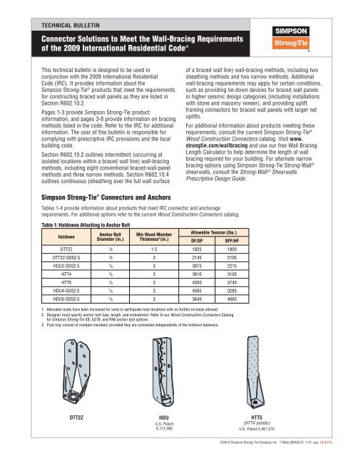
TECHNICAL BULLETIN<strong>Connec<strong>to</strong>r</strong> <strong>Solutions</strong> <strong>to</strong> <strong>Meet</strong> <strong>the</strong> <strong>Wall</strong>-<strong>Bracing</strong> <strong>Requirements</strong><strong>of</strong> <strong>the</strong> 2009 International Residential Code ®Page 2 <strong>of</strong> 8Table 2: Embedded Strap-Style HoldownsHoldownMin Wood MemberThickness 2 (in.)Tension (lbs.) (DF/SP/SPF/HF) 3,4,5Midwall/CornerEndwallLSTHD8/LSTHD8RJ 3.5 2700 2230STHD10/STHD10RJ 3.5 4120 3145STHD14/STHD14RJ 3.5 5345 42101. Allowable loads have been increased for wind or earthquake with no fur<strong>the</strong>r increase allowed.2. Post may consist <strong>of</strong> multiple members provided <strong>the</strong>y are connected independently <strong>of</strong> <strong>the</strong> holdown fasteners.3. Tension values apply <strong>to</strong> uncracked concrete in wind and low-seismic regions (any structure in seismic designcategories A and B and detached one- and two-family dwellings in seismic design category C). For allowableload information for o<strong>the</strong>r applications, refer <strong>to</strong> current Wood Construction <strong>Connec<strong>to</strong>r</strong>s catalog.4. Tension values apply <strong>to</strong> minimum concrete strength, f’c <strong>of</strong> 2500 psi, and minimum stemwall width <strong>of</strong> 8". Forvalues with minimum stemwall width <strong>of</strong> 6" refer <strong>to</strong> current Wood Construction <strong>Connec<strong>to</strong>r</strong>s catalog.5. Refer <strong>to</strong> <strong>the</strong> current Wood Construction <strong>Connec<strong>to</strong>r</strong>s catalog for installation requirements.NailedPortionClear Span17" Max.Min. rebarlength is2 x l e¹⁄₂" Min.end distance2 x l e min. or 24"Typical STHD14Corner Corner Installation InstallationTable 3: Straight StrapsStrap2 x l e 2 x l eMin. rebar lengthTypical STHD14Midwall InstallationMidwall Installation½" Min. end distanceTypical STHD14End-Of-<strong>Wall</strong> Endwall InstallationFasteners Dimensions (in.) Capacity (lbs.)(Total) W L (DF/SP/SPF/HF)LSTA21 (16) 10d 1 1/4 21 1235LSTA30 (22) 10d 1 1/4 30 1640MSTA30 (22) 10d 1 1/4 30 1820(2) LSTA30 2 (44) 10d 1 1/4 30 3280(2) MSTA30 2 (44) 10d 1 1/4 30 36401. Allowable loads have been increased for wind or earthquake load durations with no fur<strong>the</strong>r increase allowed.2. Double jack stud required; one strap installed per stud.3. Use half <strong>the</strong> nails in each member being connected <strong>to</strong> achieve <strong>the</strong> listed loads.4. 10dx1 1 ⁄2" nails may be substituted where 10d are specified at 100% <strong>of</strong> <strong>the</strong> table loads except where installed over sheathing.Min. rebarlength is 2 x l eRim Typical Joist STHD14RJInstallationRim Joist ApplicationLW¹⁄₂" Min.fromCornerT‐WALLBRACE12 1/12 exp. 12/31/15 © 2012 SImPSon STRong‐TIE ComPAny InC.LSTA and MSTA(Pilot holes not shown)
TECHNICAL BULLETIN<strong>Connec<strong>to</strong>r</strong> <strong>Solutions</strong> <strong>to</strong> <strong>Meet</strong> <strong>the</strong> <strong>Wall</strong>-<strong>Bracing</strong> <strong>Requirements</strong><strong>of</strong> <strong>the</strong> 2009 International Residential Code ®Page 3 <strong>of</strong> 8Table 4: Sill Plate AnchorsAnchor Type Model Number Size (in.) Sill Plate SizeMinimum ConcreteEnd DistancePost-Installed 1 Titen HD THD50600H 2,3 1 ⁄2"x6" Single 2x 6"Titen HD THD50800H 2,3 1 ⁄2"x8" Single 3x or Double 2x 6"Cast-in-place MASA/MASAP 4 — Single 2x or 3x 4"1. Provide plate washers beneath <strong>the</strong> anchor head when required by code. TheSimpson Strong‐Tie ® BPS 1 ⁄2-3 meets section R602.11.1 requirements.2. Mechanically-galvanized anchors may be required by code when used with treated wood.Add ‘MG’ <strong>to</strong> model number for mechanically galvanized option. For additional information,visit www.strongtie.com.3. Minimum concrete edge distance required = 1 3 ⁄4".4. ZMAX ® (galvanized G185) coating may be required by code when used with treated wood.Add ‘Z’ <strong>to</strong> model number for ZMAX option.5. Minimum concrete strength, f’c = 2500 psi.4¹⁄₄"Embedment line(Top <strong>of</strong> concrete)4"3³⁄₈"MASATiten HD ®Common <strong>Wall</strong>-<strong>Bracing</strong> Methods and Code Sections Requiring <strong>Connec<strong>to</strong>r</strong>s and AnchorsThe following wall-bracing methods and code sections require connec<strong>to</strong>rs and/or anchors. <strong>Connec<strong>to</strong>r</strong> andanchor requirements appear in bold. Refer <strong>to</strong> Tables 1-4 for Simpson Strong-Tie ® product solutions.T‐WALLBRACE12 1/12 exp. 12/31/15 © 2012 SImPSon STRong‐TIE ComPAny InC.Intermittent Narrow Braced-<strong>Wall</strong>-Panel MethodsMethod ABW: Alternate Braced <strong>Wall</strong> PanelsSection R602.10.3.2Panels shall be supported directly on a foundation or onfloor framing supported directly on a foundation that iscontinuous across <strong>the</strong> entire length <strong>of</strong> <strong>the</strong> braced wall line.Table A – Holdown Forces for Alternate Braced <strong>Wall</strong> Panels (lbs.)(Based on 2009 IRC Table R602.10.3.2)Height <strong>of</strong> Braced wall panelAlternate Braced <strong>Wall</strong>Panel Location8 ft. 9 ft. 10 ft. 11 ft. 1 12 ft. 1Minimum Shea<strong>the</strong>d Length2'– 4" ² 2'– 8" 2'– 10" 3'– 2"¹ 3'– 6"¹One-S<strong>to</strong>ry 1800 1800 1800 2000¹ 2200¹First S<strong>to</strong>ry <strong>of</strong> Two-S<strong>to</strong>ry 3000 3000 3000 3300¹ 3600¹1. Alternate braced wall panels in Seismic Design Categories D 0, D 1and D 2are limited <strong>to</strong> amaximum height <strong>of</strong> 10'.2. 8' Alternate braced wall panels in Seismic Design Categories D 0, D 1and D 2are limited <strong>to</strong>a minimum width <strong>of</strong> 2'– 8".Min. 3 /8" woodstructural panelsheathingMin. double 2x studsat each end on panelHoldown (standardor embed. style) perTable R602.10.3.2(both styles shownfor clarity) See TableA for load requirements.See Tables 1and 2 (pages 1-2) forSimpson Strong-Tieholdowns.Note: Foundation shall beconstructed per codeShea<strong>the</strong>d length(see mins. in Table A)For panel splice (if needed)adjoining panel edges shall mee<strong>to</strong>ver and be fastened <strong>to</strong> commonframing8d common or galvanized boxnails @ 6" o.c. for single s<strong>to</strong>ryor 4" o.c. for two s<strong>to</strong>ries alongpanel edges8d common or galvanized boxnails @ 12" o.c. in <strong>the</strong> fieldSimpson Strong-Tie 1 ⁄2" x 6" TitenHD ® Screw Anchor(2) 1/2" diameter anchor bolts perFigure R403.1.1 located between6" and 12" <strong>of</strong> each segment end.See Table 4 for Simpson Strong-TieoptionsMethod ABW: Alternate Braced <strong>Wall</strong> Panels
TECHNICAL BULLETIN<strong>Connec<strong>to</strong>r</strong> <strong>Solutions</strong> <strong>to</strong> <strong>Meet</strong> <strong>the</strong> <strong>Wall</strong>-<strong>Bracing</strong> <strong>Requirements</strong><strong>of</strong> <strong>the</strong> 2009 International Residential Code ®Method PFH: Portal Frame with Holdowns Section R602.10.3.3<strong>Wall</strong>s must be supported directly on a concrete foundation (not permitted on masonry foundations) andrequire additional foundation reinforcement.Extent <strong>of</strong> headerDouble portal frame (two braced wall panels)Extent <strong>of</strong> headerSingle portal frame (one braced wall panel)Page 4 <strong>of</strong> 810' - 0" max. heightFasten sheathing<strong>to</strong> header with8d common orgalvanized boxnails in 3" gridpattern at headerand 3" o.c. in allframing typ.Min. width = 16" forone-s<strong>to</strong>ry structuresMin. width = 24" foruse in <strong>the</strong> first <strong>of</strong>two-s<strong>to</strong>ry structures5/8" dia. anchor boltwith 7" min. embedmentNote: Foundation shall beconstructed per codeMin. 3" x 11.25" net headerSimpson Strong-Tie LSTA21Min. 1000 lb. strap opposite sheathingFasten <strong>to</strong>p plate <strong>to</strong> headerwith two rows <strong>of</strong> 16dsinker nails at 3" o.c. typ.Min. 2 x 4 framing6' min. - 18" max.3/8" min. thickness woodstructural panel sheathingSimpson Strong-Tie LSTHD8Min. 1000 lb. embedded holdownSimpson Strong-Tie STHD14min 4200 lb. embeddedtie-down each end <strong>of</strong> panelMin. double2 x 4 postMethod PFH: Portal Frame with HoldownsFor a panel splice (if needed),panel edges shall be blocked,and occur within 24" <strong>of</strong>mid-height. One row <strong>of</strong> typ.sheathing-<strong>to</strong>-framing nailingis required.Typical portalframe construction1/2" min enddistance typ10' - 0" max. heightMethod PFG: Portal Frame at Garage Door Openings (Seismic Design Categories A, B and C)Section R602.10.3.4Refer <strong>to</strong> Table 3 (page 2) in conjunction with Table B (page 5) for straps required due <strong>to</strong> pony wallsconstructed on headers.Fasten sheathing <strong>to</strong>header with 8d commonnails in 3" gridpattern as shown and3" o.c. in all framing(studs, blocking, andsills) typ.Min. length based on4:1 height-<strong>to</strong>-lengthratio. For example:24" for 8' height.Wood structuralpanel strength axisSimpson Strong-Tie1/2" x 6" Titen HD ®Screw AnchorAnchor bolt perR403.1.6 typ.Extent <strong>of</strong> header (one braced wall segment )Min. 3" x 11.25" net headerFasten header <strong>to</strong> king studwith (6) 16d sinker nailsFor a panel splice (if needed), paneledges shall be blocked, and occurwithin 24" <strong>of</strong> mid-height. One row <strong>of</strong>typ. sheathing-<strong>to</strong>-framing nailing isrequired in each panel.Min. (2) 2 x 4 typ.Simpson Strong-Tie LSTA21Min. 1000 lb. strap opposite sheathing2' min. - 18' maxSimpson Strong-Tie BPS 1/2-3Min. 21/2" x 21/2" x 3 /16" plate washer typ.Extent <strong>of</strong> header (two braced wall panels)No. <strong>of</strong> jack studs perTable R502.5 (1 and 2)Braced wall segmentper R602.10.4Top plate continuityper Section R602.3.2Side ElevationMin. 1000 lb.header-<strong>to</strong>-jackstrap at eachend <strong>of</strong> opening16d sinkernails in 2 rowsat 3" o.c.7/16" min. thicknesswoodstructural panelsheathingT‐WALLBRACE12 1/12 exp. 12/31/15 © 2012 SImPSon STRong‐TIE ComPAny InC.Note: Foundation shall beconstructed per codeMethod PFG: Portal Frame at Garage Door Openings in Seismic Design Categories A, B and C
TECHNICAL BULLETIN<strong>Connec<strong>to</strong>r</strong> <strong>Solutions</strong> <strong>to</strong> <strong>Meet</strong> <strong>the</strong> <strong>Wall</strong>-<strong>Bracing</strong> <strong>Requirements</strong><strong>of</strong> <strong>the</strong> 2009 International Residential Code ®Continuous Narrow Braced <strong>Wall</strong> Panel MethodsPage 5 <strong>of</strong> 8Method CS-PF: Continuous Portal FrameSection R602.10.4.1.1Refer <strong>to</strong> Table 3 (page 2) in conjunction with Table B (page 5) for straps required due <strong>to</strong> pony wallsconstructed on headers.Over Concrete or Masonry Block FoundationExtent <strong>of</strong> header (one braced wall segment)Extent <strong>of</strong> header (two braced wall segments)SideElevationPonywallheightMin. 1000 lb. tensionstrap centered atbot<strong>to</strong>m <strong>of</strong> headerT‐WALLBRACE12 1/12 exp. 12/31/15 © 2012 SImPSon STRong‐TIE ComPAny InC.12' - 0" Max. <strong>to</strong>tal wall height10' - 0" Max. heightFasten sheathing<strong>to</strong> header with 8dcommon nails in3" grid patternand 3" o.c. in allframing typ.Min. length basedon 6:1 height-<strong>to</strong>lengthratio. Forexample: 16" min.for 8' heightWood structuralpanel strength axisSimpson Strong-Tie1/2"x6" Titen HD ®Screw Anchors(2) Anchor bolts perR403.1.6Note: Foundationshall be constructedper codeOver Raised Wood Floor or Second Floor – Framing Anchor OptionMethod CS-PF: Continuous Portal Frame Panel ConstructionTable B – Tension Strap Capacity Required for Resisting Wind PressuresPerpendicular <strong>to</strong> 6:1 Aspect Ratio <strong>Wall</strong>s – Exposure B and C (Based on 2009 IRC Table R602.10.4.1.1)Mimimum <strong>Wall</strong> StudFraming Nominal Sizeand Grade2x4No. 2 GradeMin. 3" x 11.25" net headerSimpson Strong-Tie LSTA21Min. 1000 lb. strap opposite sheathingFasten header <strong>to</strong> king studwith (6) 16d sinker nailsFor a panel splice (if needed), paneledges shall be blocked, and occur withinmiddle 24" <strong>of</strong> wall height. One row <strong>of</strong> 3"nailing is required at each panel edge.Min. (2) 2 x 4 typ.2 ft. min. – 18 ft. max. (finished width)Simpson Strong-Tie THD50600HAnchor bolt per R403.1.6 typ.Simpson Strong-Tie BPS 1/2-3Min. 2" x 2" x 3 /16"plate washer typ.Simpson Strong-Tie LTP4Framing anchors670 lb. uplift, 670 lb. lateralWood structural panelsheathing over approvedband joistExposure BExposure CMax. Pony Max. TotalMax. Opening Basic Wind Speed (mph)Basic Wind Speed (mph)<strong>Wall</strong> Height <strong>Wall</strong> HeightWidth (ft.) 85 90 100 85 90 100(ft.) (ft.)Tension Strap Capacity Req’d. (lbs.) Tension Strap Capacity Req’d. (lbs.)0 10 18 1000 1000 1000 1000 1000 10009 1000 1000 1000 1000 1000 12751 1016 1000 1000 1750 1800 2325 350018 1000 1200 2100 2175 2725 DR9 1000 1000 1025 1075 1550 25002 1016 1525 2025 3125 3200 3900 DR18 1875 2400 3575 3700 DR DR9 1000 1200 2075 2125 2750 40002 1216 2600 3200 DR DR DR DR18 3175 3850 DR DR DR DR4 129 1775 2350 3500 3550 2350 350016 4175 DR DR 4175 DR DR1. Select strap from Table 3 based on capacity required2. DR = Design required.3. Strap shall be installed in accordance with manufacturer’s recommendations.No. <strong>of</strong> jack studs per tableR502.5 (1 and 2)Braced wall segmentper R602.10.4Nail sole plate <strong>to</strong>joist per tableR602.3(1)Sheathing filler ifneeded16d Sinker nails in2 rows at 3" o.c.Wood structural panelmust be continuousfrom <strong>to</strong>p <strong>of</strong> wall <strong>to</strong>bot<strong>to</strong>m <strong>of</strong> wall, orfrom <strong>to</strong>p <strong>of</strong> wall <strong>to</strong>permitted splice area.3/8" min. thicknesswood structuralpanel sheathingNail sole plate<strong>to</strong> joist per tableR602.3(1)Approvedband joist
TECHNICAL BULLETIN<strong>Connec<strong>to</strong>r</strong> <strong>Solutions</strong> <strong>to</strong> <strong>Meet</strong> <strong>the</strong> <strong>Wall</strong>-<strong>Bracing</strong> <strong>Requirements</strong><strong>of</strong> <strong>the</strong> 2009 International Residential Code ®Additional Applications that May Require <strong>Connec<strong>to</strong>r</strong>sPage 6 <strong>of</strong> 8Holdown <strong>Requirements</strong> for Continuously-Shea<strong>the</strong>d Braced <strong>Wall</strong> Panel ApplicationsSection R602.10.4.4• A 24" wood structural panel return (or 32" structural fiberboard return), as shown in Figures R602.10.4.4(1) andR602.10.4.4(2), must be provided at <strong>the</strong> ends <strong>of</strong> continuously shea<strong>the</strong>d, braced wall lines. A holdown device with amin. 800 lb. allowable tension load may be installed at <strong>the</strong> corner in lieu <strong>of</strong> <strong>the</strong> required return, as shown in FigureR602.10.4.4(3).• An exception <strong>to</strong> Section R602.10.4.4 allows for <strong>the</strong> first braced wall panel <strong>to</strong> begin up <strong>to</strong> 12'– 6" from <strong>the</strong> bracedwall line end in SDC A, B or C (8' in SDC D 0 , D 1 or D 2 ). Ei<strong>the</strong>r full-height wood structural panels (24" minimum)constructed in accordance with Figure R602.10.4.4(1) must be provided at both sides <strong>of</strong> <strong>the</strong> corner or a holdowndevice with a min. 800 lb. allowable tension load may be installed at <strong>the</strong> end <strong>of</strong> <strong>the</strong> braced wall panel closest <strong>to</strong> <strong>the</strong>corner, as shown in Figure R602.10.4.4(5).Corner detail perFiguire R602.10.4.4 (1)Clearopening heightCorner detail perFiguire R602.10.4.4 (1)Clearopening heightClearopening height= Qualified full-height bracing segmentsClearopeningheightBraced wall panels meeting minimum required length perSection R602.10.4.2 or R602.10.5 at both ends <strong>of</strong> braced wall line(all o<strong>the</strong>r framed portions <strong>of</strong> wall also shea<strong>the</strong>d)12'-6" max. – SDC A, B and C8'-0" max. – SDC D 0 , D 1 and D 2Simpson-Strong-Tie DTT2Z800 lb. capacity holdowndevice in lieu <strong>of</strong> corner returnClearopening heightSimpson-Strong-Tie DTT2Z800 lb. capacity holdown devicein lieu <strong>of</strong> corner returnClearopeningheightFigure based onR602.10.4.4 (3)Braced wall line withcontinuous sheathingwithout corner return panelFigure based onR602.10.4.4 (5)Braced wall line withcontinuous sheathing –First braced wall panelaway from end-<strong>of</strong>-wallline with holdownT‐WALLBRACE12 1/12 exp. 12/31/15 © 2012 SImPSon STRong‐TIE ComPAny InC.Braced wall panels meeting minimum required length perSection R602.10.4.2 or R602.10.5 at both ends <strong>of</strong> braced wall line(all o<strong>the</strong>r framed portions <strong>of</strong> wall also shea<strong>the</strong>d)= Qualified full-height bracing segments
TECHNICAL BULLETIN<strong>Connec<strong>to</strong>r</strong> <strong>Solutions</strong> <strong>to</strong> <strong>Meet</strong> <strong>the</strong> <strong>Wall</strong>-<strong>Bracing</strong> <strong>Requirements</strong><strong>of</strong> <strong>the</strong> 2009 International Residential Code ®Narrow <strong>Bracing</strong> AlternativesIn areas where window or door openings do not provide enough space <strong>to</strong> fit <strong>the</strong>code wall bracing options, consider using a code-listed shear wall product thatmeets <strong>the</strong> intent <strong>of</strong> <strong>the</strong> code while providing a narrow-wall solution, such as aSimpson Strong-Tie ® Strong-<strong>Wall</strong> ® shearwall (wood or steel).Refer <strong>to</strong> <strong>the</strong> Strong-<strong>Wall</strong> ® Shearwalls Prescriptive Design Guide for complete wallbracing replacement solutions, including anchorage.SteelStrong-<strong>Wall</strong> ®PanelPage 7 <strong>of</strong> 812" Min.Additional <strong>Bracing</strong> ConsiderationsO<strong>the</strong>r elements can influence wall-bracing requirements, such as construction in higher seismic design categories,installations with s<strong>to</strong>ne and masonry veneer, and braced wall panels located at exterior walls supporting ro<strong>of</strong> raftersor trusses.Braced <strong>Wall</strong> Panel LocationsSection R602.10.1.4• In SDC D 0 , D 1 or D 2 , braced wall panels must be located at each end <strong>of</strong> a braced wall line. An exception forMethod WSP braced wall panels allows a braced wall panel <strong>to</strong> begin no more than 8' from each braced wall line end,provided a minimum 24" panel is present on both sides <strong>of</strong> <strong>the</strong> corner in accordance with Figure R602.10.4.4(1),or <strong>the</strong> end <strong>of</strong> each braced wall panel closest <strong>to</strong> <strong>the</strong> corner shall have a holdown device installed with a minimumuplift capacity <strong>of</strong> 1,800 lbs. These options are shown in <strong>the</strong> figure below.T‐WALLBRACE12 1/12 exp. 12/31/15 © 2012 SImPSon STRong‐TIE ComPAny InC.Up <strong>to</strong> 8'0" max.Up <strong>to</strong> 8'0" max.Clearopening heightSimpson Strong-Tie DTT2Z1800 lb. capacity holdownMethod WSPbracing onlyClearopeningheightOR24"24"= Qualified full-height bracing segmentsUp <strong>to</strong> 8'0" max.Clearopening heightMethod WSPbracing onlyThis 24" wide segment does not countas bracing unless <strong>the</strong> building iscontinuously shea<strong>the</strong>d per R602.10.4.Figure based on Figure 602.10.1.4.1Braced wall panels at ends <strong>of</strong> braced wall lines inSeismic Design Categories D 0 , D 1 and D 2
TECHNICAL BULLETIN<strong>Connec<strong>to</strong>r</strong> <strong>Solutions</strong> <strong>to</strong> <strong>Meet</strong> <strong>the</strong> <strong>Wall</strong>-<strong>Bracing</strong> <strong>Requirements</strong><strong>of</strong> <strong>the</strong> 2009 International Residential Code ®Braced <strong>Wall</strong> Panel Uplift Load PathSection R602.10.1.2.1• Where <strong>the</strong> net uplift value exceeds 100 plf, uplift framing connec<strong>to</strong>rs shall be installed at braced wall panels <strong>to</strong>provide a continuous load path from <strong>the</strong> <strong>to</strong>p <strong>of</strong> <strong>the</strong> wall <strong>to</strong> <strong>the</strong> foundation.• Refer <strong>to</strong> <strong>the</strong> current Simpson Strong‐Tie ® Wood Construction <strong>Connec<strong>to</strong>r</strong>s catalog for connec<strong>to</strong>r options <strong>to</strong> providethat continuous load path, where required.Wind <strong>Bracing</strong> Amount Reduction with 800 lb. HoldownSection R602.10.1.2• Table R602.10.1.2(1), Note i permits <strong>the</strong> required wind bracing length <strong>to</strong> be multiplied by 0.80 for several bracingmethods and s<strong>to</strong>ry applications if min. 800 lb. holdown devices are attached <strong>to</strong> <strong>the</strong> stud at each end <strong>of</strong> each bracedwall panel.Page 8 <strong>of</strong> 8Sill AnchorageSection R403.1.6• Table 4 (page 3) provides information for postinstalled(Titen HD ® screw anchors) and cast-inplace(MASA mudsill anchors) anchors that are adirect 1:1 replacement for 1 ⁄2" diameter cast-in-placeanchor bolts embedded 7" in<strong>to</strong> concrete that areused <strong>to</strong> anchor wood sill plates.• BPS 1 ⁄2-3 washers meet <strong>the</strong> additional SectionR602.11.1 plate washer requirements <strong>of</strong> allbuildings in SDC D 0 , D 1 or D 2 , and <strong>to</strong>wnhouses inSDC C. Testing shows that <strong>the</strong> MASA can be usedin lieu <strong>of</strong> code-required anchor bolts and squarewashers in high-seismic zones.• BPS 1 ⁄2-3 washers meet <strong>the</strong> plate washerrequirements for Methods PFG and CS-PF.Titen HD ®screw anchorRound-cut washeror a plate washer asrequired by code2x, 3x or(2) 2x Mudsill6" Min.Typical MASAInstallation in ConcreteTypical MASAPInstallation in ConcreteThis technical bulletin is effective until December 31, 2013, and reflects information available as <strong>of</strong> January 1, 2012.This information is updated periodically and should not be relied upon after December 31, 2013; contactSimpson Strong‐Tie for current information and limited warranty or see www.strongtie.com.©2012 Simpson Strong‐Tie Company Inc. • P.O. Box 10789, Pleasan<strong>to</strong>n, CA 94588 T-WALLBRACE12 1/12 exp. 12/31/15800-999-5099www.strongtie.com