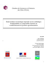
ARTICLE IN PRESS4 L. Avérous, F. Le Digabel / Carbohydrate Polymers xxx (2006) xxx–xxxAcid hydrolysisWheat straw240 KgFracti<strong>on</strong>ati<strong>on</strong>Sieving 1mmLCF80 KgHemicellulosesSugarsLCF 0-165 KgSieving 0.1mmLCF 0-0.1 LCF 0.1-1Fig. 3. Fillers fracti<strong>on</strong>s elaborati<strong>on</strong>: wheat straw fracti<strong>on</strong>ing schema.The <strong>fillers</strong> size distributi<strong>on</strong>s have been determined bylight scattering with a particles size analyzer (Mastersizer2000, Malvern Instruments, UK), in a 10 nm–2 mm range.Optical observati<strong>on</strong>s <str<strong>on</strong>g>of</str<strong>on</strong>g> the <strong>fillers</strong> are performed with atransmissi<strong>on</strong>/reflecti<strong>on</strong> microscope (Zeiss, Germany).Scanning electr<strong>on</strong> microscopy (SEM) is performed with aLEO Gemini 98 (USA) instrument to investigate the fillermorphology, at low voltage without metal coating.The compositi<strong>on</strong> <str<strong>on</strong>g>of</str<strong>on</strong>g> the <strong>fillers</strong> is determined. Lignin andmineral c<strong>on</strong>tents are determined by Klas<strong>on</strong> lignin method,according to the protocol described by M<strong>on</strong>ties (1984). Foreach sample, 300 mg (M) are added to 3 ml H 2 SO 4 . After2hat20°C, the soluti<strong>on</strong> is diluted into 40 ml <str<strong>on</strong>g>of</str<strong>on</strong>g> distilledwater. Then, the mix is carried out at reflux for 3 h. Afterfiltrati<strong>on</strong>, the solid residue is washed several times with distilledwater until neutrality <str<strong>on</strong>g>of</str<strong>on</strong>g> the filtrate is obtained. Theresidue is dried at 100 °C for 20 h and weighted (P 1 ). Thisresidue is calcinated at 500 °C for 210 min and then weighted(P 2 ) to determine the mineral c<strong>on</strong>tent. Three samples areanalysed for each filler fracti<strong>on</strong>. The Klas<strong>on</strong> lignin c<strong>on</strong>tentis determined according to Eq. (1).LigninsðKLÞ ¼ P 1 P 2ð1ÞMAfter acid hydrolysis (H 2 SO 4 ) and filtrati<strong>on</strong> to eliminatelignin and minerals, sugar titrati<strong>on</strong> allowed quantifyingthe cellulose and hemicellulose c<strong>on</strong>tents according to theprocedure described by Lequart, Ruel, Lapierre, Pollet,and Kurek (2000). This analysis is carried out with highperformance liquid chromatography (HPLC) with a Di<strong>on</strong>exÓ column (ani<strong>on</strong> exchange column). During the analysis,the different dissolved sugars are i<strong>on</strong>ized with NaOH(0.1 N) which is the mobile phase. The glucose c<strong>on</strong>centrati<strong>on</strong>gives the cellulose c<strong>on</strong>tent. The different sugars obtainedfrom hemicellulose hydrolysis are also quantified.The filler density is determined by pycnometry measurements<strong>on</strong> 10, 20, and 30% LCF filled <str<strong>on</strong>g>biocomposites</str<strong>on</strong>g> (injectedsamples) assuming there are no voids in the tested<str<strong>on</strong>g>biocomposites</str<strong>on</strong>g>.The thermal stability is determined by thermo-gravimetricanalysis with a high resoluti<strong>on</strong> TGA (2950 WATERSTA Instruments, USA) at a heating rate <str<strong>on</strong>g>of</str<strong>on</strong>g> 20 °C min 1from 30 to 550 °C. Degradati<strong>on</strong> temperatures are determined<strong>on</strong> DTG scans, at the peak maximum.Differential scanning calorimeter (DSC 2920, TAInstruments, USA) is used. Samples (between 10 and15 mg) are sealed in aluminium pans. The heating andcooling rates are 10 °C min 1 . A nitrogen flow(45 ml min 1 ) is maintained throughout the test. For allmaterials, the first scan is used for eliminating the thermalhistory <str<strong>on</strong>g>of</str<strong>on</strong>g> the material. Each sample is heated to150 °C then cooled to 50 °C before a sec<strong>on</strong>d heatingscan to 150 °C. The glass transiti<strong>on</strong> temperature (T g )and melting temperature (T m ) are determined from thesec<strong>on</strong>d heating scan. The crystallisati<strong>on</strong> temperature(T c ) is obtained from the cooling scan because the samplesare not quenched. The temperature <str<strong>on</strong>g>of</str<strong>on</strong>g> inducti<strong>on</strong> (T i )is the beginning <str<strong>on</strong>g>of</str<strong>on</strong>g> the crystallizati<strong>on</strong> during the cooling.T g is determined at the mid-point <str<strong>on</strong>g>of</str<strong>on</strong>g> heat capacity changes,T m at the <strong>on</strong>set peak <str<strong>on</strong>g>of</str<strong>on</strong>g> the endothermic and T c atthe <strong>on</strong>set peak <str<strong>on</strong>g>of</str<strong>on</strong>g> the exothermic. Three samples for eachblend are tested. By integrati<strong>on</strong> <str<strong>on</strong>g>of</str<strong>on</strong>g> the corresp<strong>on</strong>dingpeaks, we have determined the different heats <str<strong>on</strong>g>of</str<strong>on</strong>g> crystallizati<strong>on</strong>and fusi<strong>on</strong> (DH c and DH f ). These values (determinedin J/g) can be corrected from a diluti<strong>on</strong> effectlinked to the <strong>fillers</strong> incorporati<strong>on</strong> into the matrix e.g.,see Eq. (2) where ww is the filler fracti<strong>on</strong>.DH 0 c ¼DH c1 wwð2Þ
ARTICLE IN PRESSL. Avérous, F. Le Digabel / Carbohydrate Polymers xxx (2006) xxx–xxx 5The degree <str<strong>on</strong>g>of</str<strong>on</strong>g> crystallinity (in %) can be estimated with Eq.(3).X c ð%Þ ¼DH f 100ð3ÞDH 100% 1 wwTensile testing is carried out with an Instr<strong>on</strong> UniversalTesting Machine (model 4204) in tensile mode, accordingto the ASTM D882-91, with a crosshead speed <str<strong>on</strong>g>of</str<strong>on</strong>g>50 mm min 1 . Ten samples for each formulati<strong>on</strong> are tested.Before testing to stabilize the different specimens, storagec<strong>on</strong>diti<strong>on</strong>s are 23 °C and 50% RH (Relative Humidity)for 5 days. The n<strong>on</strong>-linear mechanical behaviour <str<strong>on</strong>g>of</str<strong>on</strong>g> the differentsamples is determined through different parameters.The nominal and the true strains are given by Eqs. (4) and(5), respectively. In these equati<strong>on</strong>s, L and L 0 are the lengthduring the test and at zero time, respectively. Two differentstrains are calculated; strain at the yield point (e Y )andatbreak (e b ).hei ¼ L L 0ð4ÞL 0e ¼ Ln L ð5ÞL 0The nominal stress is determined by Eq. (6), where F is theapplied load and S 0 is the initial cross-secti<strong>on</strong>al area. Thetrue stress is given by Eq. (7) where F is the applied loadand S is the cross-secti<strong>on</strong>al area. S is estimated assumingthat the total volume <str<strong>on</strong>g>of</str<strong>on</strong>g> the sample remained c<strong>on</strong>stant,according to Eq. (8). Both, stress at the yield point (r Y )and at break (r b ) are determined.hri ¼ F ð6ÞS 0r ¼ F ð7ÞSS ¼ S 0 L 0ð8ÞLYoung’s modulus (E) is measured from the slope <str<strong>on</strong>g>of</str<strong>on</strong>g> the lowstrain regi<strong>on</strong> in the vicinity <str<strong>on</strong>g>of</str<strong>on</strong>g> 0 (r = e = 0).3. Results and discussi<strong>on</strong>3.1. LCF analysisFig. 4 shows the size distributi<strong>on</strong>s <str<strong>on</strong>g>of</str<strong>on</strong>g> the different fracti<strong>on</strong>s(LCF 0–1 , LCF 0–0.1 , and LCF 0.1–1 ). LCF 0–1 presentsa double granulometric distributi<strong>on</strong>, a populati<strong>on</strong> centredat 50 lm and another <strong>on</strong>e at 700 lm. After sieving, weobtain two log-normal curves i.e., two homogeneous populati<strong>on</strong>s.A first distributi<strong>on</strong> is centred at 50 lm and another<strong>on</strong>e at 630 lm. Table 2 gives the different average sizes.Figs. 5 and 6 show both fracti<strong>on</strong>s at different magnificati<strong>on</strong>swith various observati<strong>on</strong> techniques, optical (Fig. 5)and electr<strong>on</strong> (Fig. 6) microscopies. Fig. 5 (c and d) showscoloured <strong>fillers</strong> with acidified phloroglucinol which revealsphenolic compounds as the lignin. By c<strong>on</strong>trast, we can seethe cellulose organisati<strong>on</strong> (micr<str<strong>on</strong>g>of</str<strong>on</strong>g>ibrils) in both samples.Optical micrographs (Fig. 5) show main differencesbetween both fracti<strong>on</strong>s. LCF 0–0.1 looks like a powder withpoorly-shaped fibres (Figs. 5a and c). LCF 0.1–1 is morefibrous; we show some pieces with the fibres network andthe micr<str<strong>on</strong>g>of</str<strong>on</strong>g>ibrils (Figs. 5b and d). Observati<strong>on</strong> carried outby SEM (see Fig. 6) shows very well the original organisati<strong>on</strong><str<strong>on</strong>g>of</str<strong>on</strong>g> the plant with the fibre organisati<strong>on</strong> and the micr<str<strong>on</strong>g>of</str<strong>on</strong>g>ibrils.The fracture areas <str<strong>on</strong>g>of</str<strong>on</strong>g> the fibres networks and thesubsequent defibrillati<strong>on</strong>s linked to the <strong>fillers</strong> preparati<strong>on</strong>process are shown <strong>on</strong> LCF 0.1–1 SEM micrographs (seeFigs. 6c and d). LCF 0–0.1 seems to be a mix <str<strong>on</strong>g>of</str<strong>on</strong>g> differentshapes, fibrous (short and small pieces <str<strong>on</strong>g>of</str<strong>on</strong>g> fibres) and moreor less spherical lignin-<str<strong>on</strong>g>based</str<strong>on</strong>g> particles. This diversity is dueto the impact <str<strong>on</strong>g>of</str<strong>on</strong>g> the industrial fracti<strong>on</strong>ati<strong>on</strong> process <strong>on</strong> theplant tissues. Wheat straw is composed <str<strong>on</strong>g>of</str<strong>on</strong>g> different tissueswhich are more or less destroyable during the process.On <strong>on</strong>e hand, leaves, internodes and the parenchyma (seeFig. 7) are more particularly destroyable. On the otherhand, the sclerenchyme and the fibres networks are moreresistant.Table 1 presents the chemical compositi<strong>on</strong> <str<strong>on</strong>g>of</str<strong>on</strong>g> differentvegetable fibres. Compared to the others, wheat strawshows rather low cellulose c<strong>on</strong>tent, a high lignin compositi<strong>on</strong>but also a high ash c<strong>on</strong>tent linked to a high silica fracti<strong>on</strong>.According to Zhang, Liu, and Li (1990), silica ismainly located <strong>on</strong> the leaves, 12% <str<strong>on</strong>g>of</str<strong>on</strong>g> ash in the leaves comparedto e.g., 6% in the internodes. Average value is 7–8%<str<strong>on</strong>g>of</str<strong>on</strong>g> ash in the straw (Zhang et al., 1990).Table 1 shows also the compositi<strong>on</strong>s <str<strong>on</strong>g>of</str<strong>on</strong>g> the differentLCF fracti<strong>on</strong>s. We can show the effect <str<strong>on</strong>g>of</str<strong>on</strong>g> the wheat strawtreatment. LCF shows higher lignin c<strong>on</strong>tent. Assumingthat the lignin which is insoluble is poorly affected by thehydrolysis process, the lignin quantity (in weight) staysc<strong>on</strong>stant from the initial wheat straw to the LCF 0–1 . Then,lignin can be used as a reference. Cellulose and hemicellulosec<strong>on</strong>tents have been decreased under the hydrolysistreatment. Around 40% <str<strong>on</strong>g>of</str<strong>on</strong>g> the total cellulose and 85% <str<strong>on</strong>g>of</str<strong>on</strong>g>the hemicellulose have been eliminated during the processand collected mostly in the soluble fracti<strong>on</strong> (see Table 1).We can notice that the process yield <str<strong>on</strong>g>of</str<strong>on</strong>g> hemicellulose sugarsrecovery is not total. By HPLC analysis, the hemicellulosecompositi<strong>on</strong> can be given. Hemicellulose is composed with96% <str<strong>on</strong>g>of</str<strong>on</strong>g> xylose, 3% <str<strong>on</strong>g>of</str<strong>on</strong>g> arabinose, and 1% <str<strong>on</strong>g>of</str<strong>on</strong>g> mannose.On Table 1, LCF 0–0.1 shows intermediate values betweenLCF 0–0.1 and LCF 0.1–1 . Comparing LCF 0–0.1 and LCF 0.1–1 ,we can notice that silica (ash) is more particularly presentin the finest fracti<strong>on</strong>. Then, LCF 0–0.1 must be composed,more particularly, <str<strong>on</strong>g>of</str<strong>on</strong>g> pieces <str<strong>on</strong>g>of</str<strong>on</strong>g> chopped leaves, which presenthigher silica c<strong>on</strong>tent.3.2. Biocomposites thermal propertiesTGA has been carried out to evaluate the thermalbehaviour <str<strong>on</strong>g>of</str<strong>on</strong>g> different <str<strong>on</strong>g>biocomposites</str<strong>on</strong>g> with filler c<strong>on</strong>tentfrom 0 to 40 wt. Fig. 8 and Table 3 show the main results.Until more than 10 wt%, we cannot observe the transiti<strong>on</strong>linked to the <strong>fillers</strong>. At 300 °C, the variati<strong>on</strong>s <str<strong>on</strong>g>of</str<strong>on</strong>g> weight