Operating instructions AS-i CompactLine module ... - Ifm electronic
Operating instructions AS-i CompactLine module ... - Ifm electronic
Operating instructions AS-i CompactLine module ... - Ifm electronic
Create successful ePaper yourself
Turn your PDF publications into a flip-book with our unique Google optimized e-Paper software.
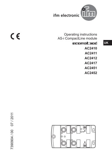
<strong>Operating</strong> <strong>instructions</strong><strong>AS</strong>-i <strong>CompactLine</strong> <strong>module</strong>UKAC2410AC2411AC2412AC2417AC2451AC24527390904 / 00 07 / 2011341 2
Contents1 Preliminary note32 Safety <strong>instructions</strong>33 Functions and features34 Installation45 Electrical connection65.1 External protective circuitry for inductive loads66 Addressing66.1 Addressing with the AC1154 addressing unit66.2 Infrared addressing67 Pin connection / data bits78 <strong>Operating</strong> and display elements109 Maintenance, repair and disposal 1110 Technical data 1111 Scale drawing122
1 Preliminary note► Instruction> Reaction, resultImportant noteNon-compliance can result in malfunction or interference.InformationSupplementary note.2 Safety <strong>instructions</strong>• Please read the operating <strong>instructions</strong> prior to set-up of the device. Ensure thatthe product is suitable for your application without any restrictions.• The device conforms to the relevant regulations and EC directives.• Improper or non-intended use may lead to malfunctions of the device or tounwanted effects in your application.• Installation, electrical connection, set-up, operation and maintenance of the devicemust only be carried out by qualified personnel authorised by the machineoperator.3 Functions and features• Maximum number of <strong>module</strong>s per master: 31• <strong>AS</strong>-interface version 2.1UK3
4 Installation►►Disconnect the system from power before installation.►►For installation choose a flat mounting surface.The entire bottom of the <strong>module</strong> must lie flat on the mounting surface.►►Screw the lower part onto the mounting surface using M4 screws andwashers (1). Tightening torque 1.8 Nm.►►Place the yellow <strong>AS</strong>-i flat cable carefully into the profile slot (AC2410, AC2451).►►Place the black <strong>AS</strong>-i flat cable for external voltage supply carefully into theprofile slot (AC2411, AC2412, AC2417, AC2452).►►Position the upper part and fix it using the supplied M3.5 screws (2).Tightening torque 1.2...1.4 Nm.►►Fix the <strong>module</strong> onto the mounting surface using M4...M5 screws andwashers (3). Tightening torque max. 1.8 Nm.Use stainless steel sleeve (E70402)* for installation in case of high mechanicalstress.►►Connect the plugs of the sensors (4) to the M12 sockets.Tightening torque max. 1 Nm.►►Cover the unused sockets with protective caps (E73004)*.Tightening torque 0.6...0.8 Nm.►►The flat cable end seal (E70413)* must be used if the <strong>module</strong> is at the end ofthe cable line.*to be ordered separatelyIn case of interference coupling to the sensor cables or the black flat cable(24 V DC auxiliary supply) the use of the functional earth springs canimprove the EMC.Requirement: An interference-free and low-resistance connection to themachine ground.► ► If necessary, you can ground the <strong>module</strong> via the functional earthsprings (5).4
ye (<strong>AS</strong>-i) bk (AUX)UK1: M4 screws and washers (not supplied with the device). Tightening torque 1.8 Nm.2: M3.5 screws supplied. Tightening torque 1.2...1.4 Nm.3: M4...M5 screw and washer (not supplied with the device).Tightening torque max. 1.8 Nm.4: M12 connector. Tightening torque max. 1 Nm.5: Functional earth springsObserve the maximum tightening torque of the connection cable.5
5 Electrical connectionThe device must be connected by a qualified electrician.The national and international regulations for the installation of electricalequipment must be adhered to.Intended for connection to class 2 (cULus class 2) circuits only.►►Disconnect power.►►Connect the device.5.1 External protective circuitry for inductive loadsThe switch-on and switch-off capacity for triggering solenoids is rated up to 20 W(IEC 947-5-2, utilisation category DC-13).Recommendation: For inductive loads use a free wheel diode on the load.ifm <strong>electronic</strong> offers valve plugs with integrated free wheel diodes.6 Addressing►►Assign a free address between 1 and 31.The address is set to 0 at the factory.6.1 Addressing with the AC1154 addressing unitThe <strong>module</strong> can be addressed via the addressing cable E70423.6.2 Infrared addressingThe safe <strong>AS</strong>-i <strong>module</strong> also offers the option of infrared addressing with the addressingunit AC1144 and the addressing cable E70211.The <strong>AS</strong>-i communication (yellow cable) must be switched off during theinfrared addressing.►►Disconnect the master.►►Supply the slaves with voltage via the <strong>AS</strong>-i power supply.When the ifm <strong>AS</strong>-i power supplies type SL are used, the communicationcan be deactivated via a jumper on the power supply.6
7 Pin connection / data bitsInputs1: sensor supply +2+4: data input3: sensor supply -5: functional earthOutputs3: external voltage AUX -4: switching output5: functional earth (FE)1,2: not connected (n.c.)3 452 13 452 1UKAC24104 inputs<strong>AS</strong>-i profile S-0.0.E / extended addressing mode: noData bit D0 D1 D2 D3Input 1 2 3 4Socket I-1 I-2 I-3 I-4Pin 2+4 2+4 2+4 2+4AC24514 inputs<strong>AS</strong>-i profile S-0.0.E / extended addressing mode: no / metal parts: high-gradestainless steelData bit D0 D1 D2 D3Input 1 2 3 4Socket I-1 I-2 I-3 I-4Pin 2+4 2+4 2+4 2+47
AC24112 inputs / 2 outputs<strong>AS</strong>-i profile S-3.0.E / extended addressing mode: noData bit D0 D1 D2 D3Input 1 2 - -Socket I-1 I-2 - -Pin 2+4 2+4 - -Output - - 3 4Socket - - O-3 O-4Pin - - 4 4AC24174 outputs<strong>AS</strong>-i profile S-8.0.F / extended addressing mode: noData bit D0 D1 D2 D3Output 1 2 3 4Socket O-1 O-2 O-3 O-4Pin 4 4 4 4AC24124 inputs / 4 outputs<strong>AS</strong>-i profile S-7.0.E / extended addressing mode: noData bit D0 D1 D2 D3Input 1 2 3 4Socket I-1 I-2 I-3 I-4Pin 2+4 2+4 2+4 2+4Output 1 2 3 4Socket O-1 O-2 O-3 O-4Pin 4 4 4 48
AC24524 inputs / 4 outputs<strong>AS</strong>-i profile S-7.0.E / extended addressing mode: no / metal parts: high-gradestainless steelData bit D0 D1 D2 D3Input 1 2 3 4Socket I-1 I-2 I-3 I-4Pin 2+4 2+4 2+4 2+4Output 1 2 3 4Socket O-1 O-2 O-3 O-4Pin 4 4 4 4UK9
8 <strong>Operating</strong> and display elements1: LED <strong>AS</strong>-i2: LED AUX (AC2411, AC2412, AC2417, AC2452)3: LED IN / OUT4: LED FAULT5: LED IR addressing10
11 Scale drawingAC2410, AC2411, AC2417, AC24516027235118,24,7 10728,5397,54,5M12x112
AC2412, AC245260UK4,7 1072723152528,5397,54,5M12x113


