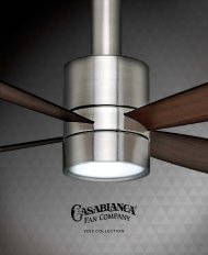
User Manual - Casablanca Ceiling Fans
User Manual - Casablanca Ceiling Fans
User Manual - Casablanca Ceiling Fans

You also want an ePaper? Increase the reach of your titles
YUMPU automatically turns print PDFs into web optimized ePapers that Google loves.
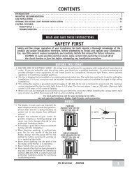
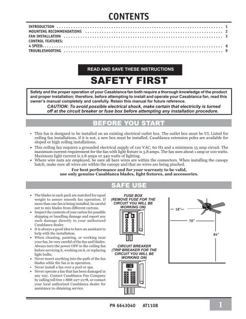
CONTENTSINTRODUCTION . . . . . . . . . . . . . . . . . . . . . . . . . . . . . . . . . . . . . . . . . . . . . . . . . . . . . . . . . . . . . . . . . . . . . . 1mounting recommendations . . . . . . . . . . . . . . . . . . . . . . . . . . . . . . . . . . . . . . . . . . . . . . . . . . . . . . . . . . 2fan INSTALLATION . . . . . . . . . . . . . . . . . . . . . . . . . . . . . . . . . . . . . . . . . . . . . . . . . . . . . . . . . . . . . . . . . . . 3control features:4 Speed. . . . . . . . . . . . . . . . . . . . . . . . . . . . . . . . . . . . . . . . . . . . . . . . . . . . . . . . . . . . . . . . . . . . . . . . . . . . 6troubleshooting . . . . . . . . . . . . . . . . . . . . . . . . . . . . . . . . . . . . . . . . . . . . . . . . . . . . . . . . . . . . . . . . . . . 9READ AND SAVE THESE INSTRUCTIONSSAFETY FIRSTSafety and the proper operation of your <strong>Casablanca</strong> fan both require a thorough knowledge of the productand proper installation; therefore, before attempting to install and operate your <strong>Casablanca</strong> fan, read thisowner’s manual completely and carefully. Retain this manual for future reference.CAUTION: To avoid possible electrical shock, make certain that electricity is turnedoff at the circuit breaker or fuse box before attempting any installation procedure.BEFORE YOU START• This fan is designed to be installed on an existing electrical outlet box. The outlet box must be UL Listed forceiling fan installations, if it is not, a new box must be installed. <strong>Casablanca</strong> extension poles are available forsloped or high ceiling installations.• This ceiling fan requires a grounded electrical supply of 120 VAC, 60 Hz and a minimum 15 amp circuit. Themaximum current requirement for the fan with light fixture is 3.8 amps. The fan uses about 1 amp or 100 watts.Maximum light current is 2.8 amps or 340 watts of lighting.• Where wire nuts are employed, be sure all bare wires are within the connectors. When installing the canopyhatch, make sure all wires are within the canopy and that no wires are being pinched.For best performance and for your warranty to be valid,use only genuine <strong>Casablanca</strong> blades, light fixtures, and accessories.SAFE USE• The blades in each pack are matched for equalweight to assure smooth fan operation. Ifmore than one fan is being installed, be carefulnot to mix blades from different cartons.• Inspect the contents of your carton for possibleshipping or handling damage and report anysuch damage directly to your authorized<strong>Casablanca</strong> dealer.• It is always a good idea to have an assistant tohelp with the installation.• When cleaning, painting, or working nearyour fan, be very careful of the fan and blades.Always turn the power OFF to the ceiling fanbefore servicing it, working on it, or replacinglight bulbs.• Never insert anything into the path of the fanblades while the fan is in operation.• Never install a fan over a pool or spa.• Never operate a fan that has been damaged inany way. Contact <strong>Casablanca</strong> Fan Companyby calling toll free 1-888-227-2178, or contactyour local authorized <strong>Casablanca</strong> dealer forassistance in obtaining service.FUSE BOX(Remove fuse for thecircuit you will beworking on)CIRCUIT BREAKER(Trip breaker for thecircuit you will beworking on)18”70”84”PN 6643040AT11081
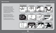
MOUNTING RECOMMENDATIONSBefore mounting your <strong>Casablanca</strong> fan, read the following helpful recommendations. The location of the fan, aircirculation, and fan size are all important factors to consider before installation.Location<strong>Ceiling</strong> fans have practical uses in almost every room in your home. We suggest you follow these mountingrecommendations as you decide where to install your <strong>Casablanca</strong> fan.• For safety reasons, the fan blades must be a minimum of 7’ above the floor.• Do not locate the fan in a doorway or above a swinging door.• In any installation, the tips of the blades must be at least 18” from the wall in orderto provide sufficient clearance for the blades.• In bedrooms, fans work best when mounted above the foot of the bed.• Over pool tables, be sure to provide plenty of clearance to avoiddamage from pool cues.• In kitchens be sure to allow for open cupboard doors to clear the fanblades.• Do not install a fan close to, or over, a pool or spa. High humiditycombined with corrosive gases will destroy the finish and warp theblades.Fan SizeVariable fan speed capability permits the use of a full-size 52” fan even insmaller rooms. For very large rooms, two fans may be needed.Suggested Extension Pole<strong>Ceiling</strong> Height Pole Length8”Standard8’ 6” Standard9”6”9’ 6”12”10”12”11”18”12”24”13”36”14”48”SLOPED CEILING INSTALLATIONSExtensionPolemaximumangle 32ºblades must bea minimum of 7’above the floorWhen to Use Extension PolesFor best performance and best appearance,an extension pole should be used with your<strong>Casablanca</strong> fan when installing on high(cathedral) ceilings or sloped ceilings. <strong>Casablanca</strong>offers standard poles in incrementsof 6″ up to 5″. Custom poles are availablein lengths up to 9′9″. See your Authorized<strong>Casablanca</strong> Dealer for details.7’ minimumNote: Fan may wobble orvibrate if pole length is notlong enough and inside blade istoo close to downslope or sidewall. Extending pole length willusually solve problem.Calculation of 32°Use the tear-off <strong>Ceiling</strong> Angle Template card insertedin the back of this manual, it provides you with asimple ‘go’ or ‘no-go’ for installing your fan on a slopedceiling.2EXAMPLE 1This slope is less than 32°.It is OK to install your fan.EXAMPLE 2This slope is 32°. This is the maximumslope that will allow the fan to hangstraight down. It is OK to installyour fan.EXAMPLE 3This slope is more than 32°.Your fan will not hang straight down,an adaptor is necessary. Contact yourlocal Authorized <strong>Casablanca</strong> Dealer inregards to purchasing a “Slope <strong>Ceiling</strong>Adaptor.”
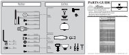
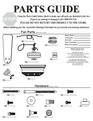
Pa n a m a ® Ha l oINSTALLATION INSTRUCTIONSUnpacking: Before assembling and installing your ceiling fan, remove all parts from the shipping cartons and check them against the partslisted here. Before discarding packaging material, be certain that all parts have been removed.getting startedCarton ContentsThe fan carton contains the fan body, warranty card, owner’s manual, and all the parts neccessary ( except blades) to assemble and installyour <strong>Casablanca</strong> ceiling fan. These parts are shown at the start of each installation section. before you start, go through thie Owner’s manulasand confirm thaat you have all the parts shown in each section. Be Sure to use only genuine <strong>Casablanca</strong> blades, The blade shrink wrap holds 5blades of matched weight. If more than one fan is being installed, be sure not to mix blade setsCaution: When removing the shrink wrap, be careful not to scratch the blades.perma•lock hardwareALLEN SETSCREW1¦ 4 -20 x 1 ¦ 4 ”(pre-installed)3mmallen wrenchFan preparationdownrod & Ballassemblyimportant safety information!before starting the installation of your ceiling fan,install the threaded downrod into the motor couplingand lock the assemblyPrepare for fan installation as follows:Step A. Route the wires from the motor through thePerma•Lock downrod and ball assembly.Tip: The downrod has a tapered thread that is designedto lock completely when correctly installed.Step B. Using the provided allen wrench, loosen the setscrew several turns to allow installation of the downrod.Thread the downrod into the motor coupling until it stopsturning, this will take at least four and a half full turns.Step C. Securely tighten the set screw with the providedallen wrench to ensure safe operation of your fan.CAUTION: Failure to fully lock in the downrodbefore securely tightening the set screwmay cause the fan to separate from thedownrod during normal operation!taperedthreadALLENSET SCREWCEILING HARDWAREmotorwiresgroundwiredownrod& BallassemblymotorcouplingCROSSBARMOUNTINGBRACKETWIRE NUT (4)additional hardware1” x 8-32 roundhead screws (2)support installationLag screw3/8”7 x 5”2 1 / 4 ” x 8-32 roundhead screws (2)large flatwasher 3/8”FLAT WASHER(2)3
Crossbar Mounting Bracket INSTALLATIONNote: After removing the old fixture, check the outletbox to insure that it is supported by a joist or beamacross its upper surface. If not, a 2” x 4” stud mustbe installed.JOISTStep 1. Remove the knockout plug in the center of theoutlet box or drill a 1 /2” hole for the lag screw to passthrough. Then drill a 1 /4” guide hole into the joist or beamto a depth of 3”.Step 2. Route the outlet box wires through the keyholeslot of the crossbar mounting bracket as shown. Attach thecrossbar mounting bracket to outlet box with screws provided,assuring that the outlet box wires are not pinchedby the washer.CAUTION: To reduce the risk of personalinjury, use only the mounting hardware providedwith the approved outlet box to installthe crossbar mounting bracket.ceiling fanapprovedwiring boxcrossbarmountingbracketflatwasherceilingwiringridge sidedowngreen groundwireWARNING!SUPPORT DIRECTLY TOBUILDING STRUCTURE ONLY.approved outletbox hardwareStep 3. With the large washer attached, pass the lagscrew through the center hole of the crosbar mountingbracket and screw into guide hole. Tighten until outletbox is firmly mounted to beam. This box must be firmlysecured to the ceiling. We recommend that the ceilingfixture outlet box be of sufficient capacity enabling itto support the weight of fan and light fixture under anyconditions.LAG SCREW INSTALLATIONlagscrewLARGEWASHERCANOPY HARDWARECANOPY SCREW (4)CANOPYHATCHCANOPYCANOPY LOCK WASHER(4)4
Step 4. To hang the fan body in the canopy, hold the fanbody firmly and insert the ball into the canopy opening.Check that no wires were pinched. Rotate the fan bodyuntil the slot in the nylon ball fits into the pin oppositethe canopy opening.Note: Independent control ofthe light fixture using a W-81 requiresan additional power wirerun from the wall switch to thefan. See Page 10 for wiring.Pa n a m a ® Ha l oHANGING THE FANballslotpinFan Weighs 27 lbsCANOPY ELECTRICAL CONNECTIONSStep 4a. Attach the fan wires to the ceiling fixtureoutlet box wiring by twisting the bare ends of the wirestogether and then securing with a wire nut. Test that theconnection is secure by pulling on the wire nut. Conectin this order:2 BLACK WIRES2 WHITE WIRESStep 4b. Wiring Connections• GREEN leads from mounting plate and fan toGROUND conductor of power source. Secure withwire nut.• WHITE wire from fan to white NEUTRAL wire inceiling fixture outlet box. Secure with wire nut.• BLACK power wire from fan to BLACK power wire inceiling outlet box. Secure with wire nut.3 GREENWIRESStep 5. Tuck the wires into the canopywith the wire nuts pointed upwards,so that the WHITE and BLACK wiresare on opposite sides of the canopyand all wires are clear of the canopyopening.Step 6. Install canopy hatch with thelast canopy screw and lock washer. Todo this, tilt the fan body away from thehatch opening.Tighten the screws firmly by handonly,Step 7. Straighten the fan, then checkto ensure that there is no movementbetween the canopy and ceilingor Hang-Tru ball and top supportshaft.CANOPY HATCH INSTALLATIONlockwashercanopyhatchcanopyscrewtilt the fan to installlast canopy screw5
Step 8.Attach the blades to the blade holderswith the three blade screws and feltwashers provided for each blade.Hand tighten securely.Install the assembled blade and bladeholder to the flywheel (round holes)or direct drive motor.Hand tighten securely.blade holder & BLADEBLADE HOLDER SCREW(2 PER BLADE HOLDER)BLADE SCREW(3 PER BLADE)felt washer(3 PER BLADE)Repeat for each assembly.BLADEWARNING: To reduce the risk of personal injury, donot bend blade holders when installing, balancing,or cleaning. Do not insert foreign objects betweenrotating fan blades.6
4 - speed operationPull-chain switches on the fan control the fan and lights.Using the fan control pull-chain switch: Fan offat start.Optional light pullChain switchFirst pull: fan ON, High speedSecond pull: Medium speedThird pull: Medium Low speedFourth pull: Low speedFifth pull: Fan OFFThe sequence of Light pull chain as follows:Light off at StartFirst pull: Up LightSecond pull: Down Light (Optional Light Kit If Installed)Third pull: Up & Down LightFourth pull: OffDirection of blade rotation is controlled by the reverseslide switch on the side of the switch housing. No changesin household wiring are required.4 - speed optional Light Fixture installation1. Refer to light kit instructions to assemble and attachyour light kit correctly.2. Remove the two 8-32 screws from the switch housingcap.3. Remove the plug from switch housing.4. Install pull-chain switch and Finger tighten collar onswitch.5. Connect one wire from pull-chain switch to theBLUE D1-Option wire. Secure splice with a wire nut.6. Connect other wire from pull-chain switch to BLACKwire from light kit. Secure splice with a wire nut.7. Connect WHITE wire from switch housing to WHITEwire from light kit. Secure splice with a wire nut.8. At the canopy, connect the BLACK and BLUE wires.4 - speed optional Wall Control w-41The W-41 wall control provides four-speed control of fan from a convenientwall location. The W-41 is designed to replace a standard wall switch andwill fit wall boxes with a depth of 2” or greater. Not for use with singlepull-chain fan/light option wiring. To install a W-41 wall control inplace of an existing wall switch, follow the instructions on the W-41 package.Note: No rewiring is required if the fan is replacing an existing light Fixture.Operation of the fan from the wall switch is simple:1. Turn knob to obtain desired speed setting.switchhousingwhiteblack4-SPEEDreverselight fixtureFan & speed controlpull chain switchcollarBlue d-1CAUTION! Failure to set the pull-chain speed to HIGH canresult in faulty operation of the fan and damage to the W-41wall control. To confirm fan is set to HIGH: TurnW-41 fanspeed switch to ‘HI’ - set fastest fan speed with pull chain.7
R4 - speed optional wall control W-81The W-81 wall control provides separate control of fan and light with two separateknobs from a convenient wall location. The W-81 is designed to replace a standardwall switch and wall boxes with a depth of 2” or greater. Requires two hot leads fromwall box to ceiling wiring box.To install a W-81 wall control in place of an existingwall switch, follow the instructions on the W-81 package.Operation of the fan from the wall switch is simple:1. Turn the upper knob to the desired fan speed.2. Turn the lower knob to the desired light setting.OFFLOOFFMEDMEDHIHIMAXCAUTION! Failure to set the pull-chain speed to HIGH can result infaulty operation of the fan and damage to the W-81 wall control. Toconfirm fan is set to HIGH: TurnW-81 fan speed switch to ‘HI’ - setfastest fan speed with pull chain.4 - speed W-41 wall control of the fan• The W-41 allows the choice of four (4)different speed settings.• No light fixture is used.• Set the FAN pull chain switch to theHIGH speed setting.• No changes in household or fan wiringare required.• The fan may be turned ON and OFF bythe W-41 wall control.CAUTION! Failure to set the pull-chain speedto HIGH can result in faulty operation of thefan and damage to the W-41 wall control.To confirm fan is set to HIGH: TurnW-41 fanspeed switch to ‘HI’ - set fastest fan speedwith pull chain.4 - speed W-81 Wall control of the fan & light• The fan may be turned ON and OFFby the W-81 wall control.• The lights may be turned ON andOFF by the W-81 and the intensityadjusted from low to high.• The fan must be supplied withtwo independent 120V AC supplywires.• Set the FAN pull chain switch tothe HIGH speed setting.• Turn the lights ON at the fan.• The W-81 allows the choice of four(4) different speed settings.CAUTION! Failure to set the pull-chain speedto HIGH can result in faulty operation of thefan and damage to the W-81 wall control.To confirm fan is set to HIGH: TurnW-81 fanspeed switch to ‘HI’ - set fastest fan speedwith pull chain.8
Pa n a m a ® Ha l oTroubleshootingBefore Requesting Service:Please follow this troubleshooting guide before contacting your dealer for assistance.Caring for Finishes: For cleaning, a soft brush or lint-freecloth should be used to prevent scratching the finish. A vacuumcleaner brush nozzle can remove heavier dust. Surface smudgesor an accumulation of dirt and dust can easily be removed byusing a mild detergent and slightly dampened soft cloth. Anantistatic agent may be used, but never use abrasive cleaningagents. These will damage the finish. Painted and high-glossblades may be cleaned in the same manner.Blades: Wood finish blades should be cleaned with a furniturepolishing cloth. Occasionally, a light coat of furniture polishmay be applied for added protection and beauty.PROBLEMNever Lubricate this Fan!The precision motor at the heart of your Airflow fan featuressealed bearings that are lubricated for life. Do not attempt tooil the motor.Changing Light BulbsBe sure to turn power to the fan OFF at the wall switch or circuitbreaker before changing light bulbs. Replace bulbs withsame type as removed from the fixture. Each fan is rated for amaximum TOTAL wattage of lighting.Exceeding the rated maximum allowable wattage for the fanwill burn out the fan electronics module and void the warranty.POSSIBLE remedies..FAN WILL NOT START •Check main circuit fuses, circuit breakers, or wall switch position. Check all wire connections,making sure the power is turned off during this inspection.•Pin connectors are not making good contact. Check the connections in the switch housing andunder the top cover.•Battery weak - install fresh battery.•Fan receiver defective - replace.•Check receiver (fan) and transmitter (remote control) dip switch settings to see if they are bothset to the same frquency.FAN WOBBLES OR •Be sure canopy pin is properly set into the slot on the ball.SHAKES EXCESSIVELY •Check that bladeholders have not been bent during installation and blades are balanced.•Hanger bracket and/or ceiling outlet are loosely attached: Make sure that the hanger bracket istightly attached to the ceiling outlet box. Make sure that the downrod assembly is secured firmly•Downrod is loosely attached to downrod base: Make sure that all screws are securely tightenedFAN NOISY DURINGOPERATIONDOES NOT RUN ONLOW SPEEDBATTERY LIFESEEMS SHORT•Check and tighten light fixture retaining screws, glass shade screws and/or the light bulb(s).•Tighten canopy screws and mounting plate assembly. Check that the wire nuts inside the canopyand switch housing are not touching the metal parts or have fallen off the wire splices. Tighten asnecessary.•Tighten blade holders to flywheel (or direct drive motor)/and blade to bladeholder screws.•Make sure all screws in the motor housing are snug, but not overly tight. Defective bulb: Replacebulb.•If new, “break-in” may be required - run at higher speed for several days.•Not using Alkaline batteries: Replace with Alkaline batteries.FAN RUNS SLOWLY IN EITHER DIRECTION IF ROTATION IS STARTED BY HAND; WILL NOT REVERSE:Defective reverse switch; defective capacitor; or open motor winding: Replace reverse switch assembly; replace PCBassembly; or replace motor unit.FAN WILL NOT OPERATE AT PROPER SPEEDS OR WILL NOT OPERATE AT ANY SPEED: Defectivethree-speed pull-chain switch assembly; or defective capacitor: Replace three-speed pull-chain switch assembly;or replace PCB9
Model Name:Model Number:Panama® Halo66HXXFDimensions: A = 10.75"B = 12.46"NOTE: Dimension Bincludes light fixtureand glass.Weight:C = 3"D = 13.43"E = 5.6"27 lbs.Product SpecificationsMotor:XTR200® x 20mmBlade Span: 42" or 50"Blade Iron Pitch: 20°No. of Blades: 5Technology: 4-SpeedAirflow*:Electricity Use*:Airflow Efficiency*:6,480 cfm84 watts73 cfm/watt* Performance data is for fan only. No lighting wattage is included.Measurements taken with 21" basic blades.10