Owner's Manual - Casablanca Fan
Owner's Manual - Casablanca Fan
Owner's Manual - Casablanca Fan
- No tags were found...

You also want an ePaper? Increase the reach of your titles
YUMPU automatically turns print PDFs into web optimized ePapers that Google loves.
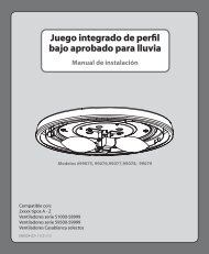
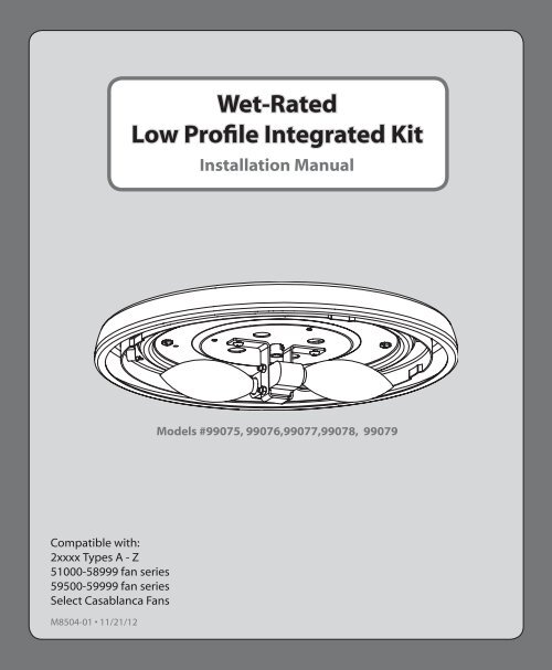
Wet-RatedLow Profile Integrated KitInstallation <strong>Manual</strong>Models #99075, 99076,99077,99078, 99079Compatible with:2xxxx Types A - Z51000-58999 fan series59500-59999 fan seriesSelect <strong>Casablanca</strong> <strong>Fan</strong>sM8504-01 • 11/21/12
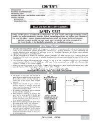
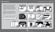
1.888.830.1326 1.888.830.1326BEFORE YOU BEGINRead entire installation instructions carefully beforebeginning installation and save these instructions.WHICH ASSEMBLY METHOD WILL I USE?Choose one of the four images below that most closely resembles the switchhousing on your fan; then follow the instructions under the image.SwitchHousingCapScrewSwitchHousingCapSwitchHousingScrewSwitchHousingCapYour light kit is compatible with most ceiling fans. The light kit will attach to the fan’sswitch housing. Begin on page 3 where you will choose the type of switch housing thatmost closely resembles the one on your fan. From there, you will be directed to the set ofassembly instructions that are appropriate for installing the light kit to your fan.If your fan’s switch housing cap resemblesthis one, remove the cap screws with aPhillips head screwdriver. Then follow theTYPE-A ASSEMBLY INSTRUCTIONS onpages 4-5.If your fan’s switch housing cap resemblesthis one, remove the whole switchhousing by removing the switch housingscrews with a Phillips head screwdriver.Remove the two cap screws from theinside of the switch housing. Reinstallthe switch housing. Tighten the switchhousing screws. Then follow the TYPE-AASSEMBLY INSTRUCTIONS on pages 4-5.READ AND SAVE THESE INSTRUCTIONSThis product conforms to UL Standard 507.WARNINGSw.1 - To reduce the risk of fire, electrical shock, or personal injury, mount fan directly from buildingstructure and/or an outlet box marked acceptable for fan support of 70 lbs (31.8 kg) and use themounting screws provided with the outlet box.w.2 - To avoid possible electrical shock, before installing or servicing your fan, disconnect the power byturning off the circuit breakers to the outlet box and associated wall switch location. If you cannot lockthe circuit breakers in the off position, securely fasten a prominent warning device, such as a tag, to theservice panel.CAUTIONSc.1 - All wiring must be in accordance with national and local electrical codes ANSI/NFPA 70. If you areunfamiliar with wiring, use a qualified electrician.SwitchHousingScrewPlugButtonIf your fan’s switch housing cap resemblesthis one, remove the whole switchhousing by removing the switch housingscrews with a Phillips head screwdriver.Remove the plug button. Then follow theTYPE-B ASSEMBLY INSTRUCTIONS onpages 6-7.PlugButtonSwitchHousingScrewIf your fan’s switch housing cap resemblesthis one, remove the whole switchhousing by removing the switch housingscrews with a Phillips head screwdriver.Remove the plug button using a standardscrewdriver. Then follow the TYPE-CASSEMBLY INSTRUCTIONS on pages 8-9.2 3M8504-01 • 11/21/12 M8504-01 • 11/21/12
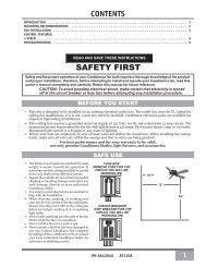
1.888.830.1326 1.888.830.13261TYPE-A ASSEMBLY INSTRUCTIONS25TYPE-A ASSEMBLY INSTRUCTIONS (CONTINUED)6BulbTabSocketIndentationSwitchHousingWireConnectorMountingScrewFeed the wires through the center holein the gasket. Then partially install thetwo mounting screws through thegasket into the bottom of the lowerswitch housing. Press the gasket flush tothe lower switch housing.3If your fan does not have pin connectorson the wires coming from the switchhousing, install the wiring harnessprovided. Using the provided wireconnectors connect the white wire fromthe fan to the white wire from the wireharness and connect the black or bluewire from the fan to the black wire fromthe wire harness.4 7Installing the bulbs - Install a bulbinto each of the sockets. Whennecessary, replace with bulbs of sametype and wattage.Installing the globe (sold separately)-Position the indentations in the outer rim ofthe globe so that they line up with the tabson the inside surface of the light fixture rim.Carefully lift the globe up inside the lightfixture as far as it will go. Rotate the globe ina clockwise direction until it is held tightlyin place by the four tabs.8MountingScrewKeyholeSlotsTurn PowerONUsing the single pin connectors, connectthe black or blue wire from the fan to theblack wire from the light kit. Connect thewhite wire from the fan to the white wirefrom the light kit.Lift the light kit up to meet thelower switch housing. Wrap keyholeslots around the screws and twistcounterclockwise. Tighten screws.Installing the pull chain pendant -Attach the pull chain pendant to theend of the short chains coming from theswitch housing and the light kit.Turn power on. Your installationis complete!Do not allow the light kit to hang4 only by the wire connections!5M8504-01 • 11/21/12 M8504-01 • 11/21/12
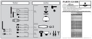
1.888.830.1326 1.888.830.13261TYPE-B ASSEMBLY INSTRUCTIONS25TYPE-B ASSEMBLY INSTRUCTIONS (CONTINUED)6BulbTabSocketIndentationSwitchHousingWireConnectorIf your fan does not have pin connectorson the wires coming from the switchhousing, install the wiring harnessprovided. Using the provided wireconnectors connect the white wire fromthe fan to the white wire from the wireharness and connect the black or bluewire from the fan to the black wire fromthe wire harness.3Feed the wires through the center hole inthe switch housing, the washer, and the nut.Push the center hole in the gasket over thethreaded rod of the light kit. Then install theswitch housing by twisting clockwise ontothe threaded rod. Install the washer and nutonto threaded rod and tighten securely.4Installing the bulbs - Install a bulbinto each of the sockets. Whennecessary, replace with bulbs of sametype and wattage.7Installing the globe (sold separately)-Position the indentations in the outer rim ofthe globe so that they line up with the tabson the inside surface of the light fixture rim.Carefully lift the globe up inside the lightfixture as far as it will go. Rotate the globe ina clockwise direction until it is held tightlyin place by the four tabs.8SwitchHousingScrewTurn PowerONUsing the single pin connectors, connectthe black or blue wire from the fan to theblack wire from the light kit. Connect thewhite wire from the fan to the white wirefrom the light kit.Lift the light kit assembly up so that thescrew holes in the lower switch housingline up with the holes in the upper switchhousing. Install the switch housingscrews and tighten securely.Installing the pull chain pendant -Attach the pull chain pendant to theend of the short chains coming from theswitch housing and the light kit.Turn power on. Your installationis complete!Do not allow the light kit to hang6 only by the wire connections!7M8504-01 • 11/21/12 M8504-01 • 11/21/12
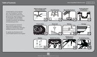
1.888.830.1326 1.888.830.13261TYPE-C ASSEMBLY INSTRUCTIONS25TYPE-C ASSEMBLY INSTRUCTIONS (CONTINUED)6BulbTabSocketIndentationSwitchHousingWireConnectorIf your fan does not have pin connectorson the wires coming from the switchhousing, install the wiring harnessprovided. Using the provided wireconnectors connect the white wire fromthe fan to the white wire from the wireharness and connect the black or bluewire from the fan to the black wire fromthe wire harness.3Feed the wires through the center hole inthe switch housing. Then using the singlepin connectors, connect the black or bluewire from the fan to the black wire fromthe light kit. Connect the white wire fromthe fan to the white wire from the light kit.4Installing the bulbs - Install a bulbinto each of the sockets. Whennecessary, replace with bulbs of sametype and wattage.7Installing the globe (sold separately)-Position the indentations in the outer rim ofthe globe so that they line up with the tabson the inside surface of the light fixture rim.Carefully lift the globe up inside the lightfixture as far as it will go. Rotate the globe ina clockwise direction until it is held tightlyin place by the four tabs.8LowerSwitchHousingUpperSwitchHousingThreadedRodSwitchHousingScrewTurn PowerONLift the lower switch housing up so that thescrew holes line up with the holes in theupper switch housing. Install the switchhousing screws and tighten securely.Lift the light kit up, tucking the wires intothe hole in the switch housing. Install thecenter stem of the light kit into the lowerswitch housing by turning the threadedrod clockwise into the threaded hole.Continue turning until tight.Installing the pull chain pendant -Attach the pull chain pendant to theend of the short chains coming from theswitch housing and the light kit.Turn power on. Your installationis complete!Do not allow the light kit to hang8 only by the wire connections!9M8504-01 • 11/21/12 M8504-01 • 11/21/12
1.888.830.1326Lights don’t come on.TROUBLESHOOTING• Make sure that the bulbs are properly installed.• Make sure power switch is on.• Pull the pull chain to make sure it is on.• Check the circuit breaker to ensure the power is turned on.• Check the pin connections in the light kit.• Refer to the fan manual for locating the fan’s wiring. Verify that the light and powerwires are correctly connected to the ceiling and the light kit.ONE YEAR WARRANTYThis product is warranted to the original purchaser by <strong>Casablanca</strong> <strong>Fan</strong> Company/Hunter <strong>Fan</strong> Company against defects in material and workmanship for one (1)year from date of purchase. During the warranty period, we will repair or, at ouroption, replace a defective product at no charge. For information on how to obtainservice, contact the <strong>Casablanca</strong>/Hunter Service Department by calling our tollfreenumber at 888-830-1326. Damage to the product caused by mishandling,improper installation or modification is not covered by this warranty. This warrantyis given in lieu of all other warranties expressed or implied. Some states do not allowlimitations of time on an implied warranty, therefore the above limitations may notapply in every case. This warranty states specific legal rights which may vary fromstate to state.If you have problems installing or operating your light kit, do not return this productto the dealer. Call our Consumer Affairs Hotline.888-830-1326Monday through Friday8:00 am to 4:30 pm Central10M8504-01 • 11/21/12