Owner's Manual - Casablanca Fan
Owner's Manual - Casablanca Fan
Owner's Manual - Casablanca Fan
- No tags were found...

You also want an ePaper? Increase the reach of your titles
YUMPU automatically turns print PDFs into web optimized ePapers that Google loves.
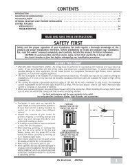
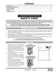
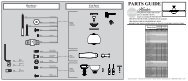
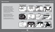
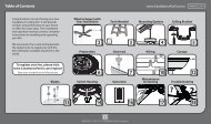
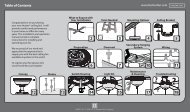
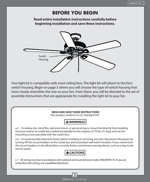
1.888.830.1326 1.888.830.1326BEFORE YOU BEGINRead entire installation instructions carefully beforebeginning installation and save these instructions.WHICH ASSEMBLY METHOD WILL I USE?Choose one of the four images below that most closely resembles the switchhousing on your fan; then follow the instructions under the image.SwitchHousingCapScrewSwitchHousingCapSwitchHousingScrewSwitchHousingCapYour light kit is compatible with most ceiling fans. The light kit will attach to the fan’sswitch housing. Begin on page 3 where you will choose the type of switch housing thatmost closely resembles the one on your fan. From there, you will be directed to the set ofassembly instructions that are appropriate for installing the light kit to your fan.If your fan’s switch housing cap resemblesthis one, remove the cap screws with aPhillips head screwdriver. Then follow theTYPE-A ASSEMBLY INSTRUCTIONS onpages 4-5.If your fan’s switch housing cap resemblesthis one, remove the whole switchhousing by removing the switch housingscrews with a Phillips head screwdriver.Remove the two cap screws from theinside of the switch housing. Reinstallthe switch housing. Tighten the switchhousing screws. Then follow the TYPE-AASSEMBLY INSTRUCTIONS on pages 4-5.READ AND SAVE THESE INSTRUCTIONSThis product conforms to UL Standard 507.WARNINGSw.1 - To reduce the risk of fire, electrical shock, or personal injury, mount fan directly from buildingstructure and/or an outlet box marked acceptable for fan support of 70 lbs (31.8 kg) and use themounting screws provided with the outlet box.w.2 - To avoid possible electrical shock, before installing or servicing your fan, disconnect the power byturning off the circuit breakers to the outlet box and associated wall switch location. If you cannot lockthe circuit breakers in the off position, securely fasten a prominent warning device, such as a tag, to theservice panel.CAUTIONSc.1 - All wiring must be in accordance with national and local electrical codes ANSI/NFPA 70. If you areunfamiliar with wiring, use a qualified electrician.SwitchHousingScrewPlugButtonIf your fan’s switch housing cap resemblesthis one, remove the whole switchhousing by removing the switch housingscrews with a Phillips head screwdriver.Remove the plug button. Then follow theTYPE-B ASSEMBLY INSTRUCTIONS onpages 6-7.PlugButtonSwitchHousingScrewIf your fan’s switch housing cap resemblesthis one, remove the whole switchhousing by removing the switch housingscrews with a Phillips head screwdriver.Remove the plug button using a standardscrewdriver. Then follow the TYPE-CASSEMBLY INSTRUCTIONS on pages 8-9.2 3M8504-01 • 11/21/12 M8504-01 • 11/21/12