Owner's Manual - Casablanca Fan
Owner's Manual - Casablanca Fan
Owner's Manual - Casablanca Fan

You also want an ePaper? Increase the reach of your titles
YUMPU automatically turns print PDFs into web optimized ePapers that Google loves.
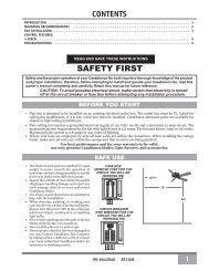
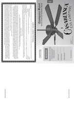
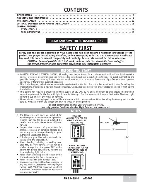
CONTENTSINTRODUCTION . . . . . . . . . . . . . . . . . . . . . . . . . . . . . . . . . . . . . . . . . . . . . . . . . . . . . . . . . . . . . . . . . . . . . . 1mounting recommendations . . . . . . . . . . . . . . . . . . . . . . . . . . . . . . . . . . . . . . . . . . . . . . . . . . . . . . . . . . 2fan INSTALLATION . . . . . . . . . . . . . . . . . . . . . . . . . . . . . . . . . . . . . . . . . . . . . . . . . . . . . . . . . . . . . . . . . . . 10OPTIONAL EXCLUSIVE LIGHT FIXTURE INSTALLATION . . . . . . . . . . . . . . . . . . . . . . . . . . . . . . . . . . . . . . . . . . . 11control features:Versa•Touch 2 . . . . . . . . . . . . . . . . . . . . . . . . . . . . . . . . . . . . . . . . . . . . . . . . . . . . . . . . . . . . . . . . . . 14troubleshooting . . . . . . . . . . . . . . . . . . . . . . . . . . . . . . . . . . . . . . . . . . . . . . . . . . . . . . . . . . . . . . . 16READ AND SAVE THESE INSTRUCTIONSSafety and the proper operation of your <strong>Casablanca</strong> fan both require a thorough knowledge of theproduct and proper installation; therefore, before attempting to install and operate your <strong>Casablanca</strong>fan, read this owner’s manual completely and carefully. Retain this manual for future reference.CAUTION: To avoid possible electrical shock, make certain that electricity is turned off atthe circuit breaker or fuse box before attempting any installation procedure.• CAUTION: RISK OF ELECTRICAL SHOCK! All wiring must be performed in accordance with national and local electricalcodes. If you are unfamiliar with the wiring codes, you should use a qualified electrician. To avoid overheating andpossible damage to other equipment, do not install control to a receptacle, fluorescent light fixture, motor operatedappliance, or transformer-supplied appliance.• This fan is designed to be installed on an existing electrical outlet box. The outlet box must be UL Listed for ceiling faninstallations, if it is not, a new box must be installed. <strong>Casablanca</strong> extension poles are available for sloped or high ceilinginstallations.• This ceiling fan requires a grounded electrical supply of 120 VAC, 60 Hz and a minimum 15 amp circuit. The maximumcurrent requirement for the fan with light fixture is 3.8 amps. The fan uses about 1 amp or 100 watts. Maximum lightcurrent is 2.8 amps or 340 watts of lighting.• Where wire nuts are employed, be sure all bare wires are within the connectors. When installing the canopy hatch, makesure all wires are within the canopy and that no wires are being pinched.For best performance and for your warranty to be valid,use only genuine <strong>Casablanca</strong> blades, light fixtures, and accessories.• The blades in each pack are matched forequal weight to assure smooth fan operation.If more than one fan is being installed, becareful not to mix blades from differentcartons.• Inspect the contents of your carton forpossible shipping or handling damage andreport any such damage directly to yourauthorized <strong>Casablanca</strong> dealer.• It is always a good idea to have an assistantto help with the installation.• When cleaning, painting, or working nearyour fan, be very careful of the fan andblades. Always turn the power OFF to theceiling fan before servicing it, working onit, or replacing light bulbs.• Never insert anything into the path of thefan blades while the fan is in operation.• Never install a fan over a pool or spa.• Never operate a fan that has been damaged inany way. Contact <strong>Casablanca</strong> <strong>Fan</strong> Company bycalling 1-888-227-2178, or contact your localauthorized <strong>Casablanca</strong> dealer for assistancein obtaining service.SAFETY FIRSTBEFORE YOU STARTNOTESFUSE BOX(Remove fuse for thecircuit you will beworking on) 18″CIRCUIT BREAKER(Trip breaker for thecircuit you will beworking on)PN 8943540AT070870″84″1
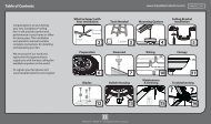
MOUNTING RECOMMENDATIONSBefore mounting your <strong>Casablanca</strong> fan, read the following helpful recommendations. The location of the fan, air circulation,and fan size are all important factors to consider before installation.LocationCeiling fans have practical uses in almost every room in your home. We suggest you follow these mountingrecommendations as you decide where to install your <strong>Casablanca</strong> fan.• For safety reasons, the fan blades must be a minimum of 7’ above the floor.• Do not locate the fan in a doorway or above a swinging door.• In any installation, the tips of the blades must be at least 18” from the wall in order to provide sufficientclearance for the blades.• In bedrooms, fans work best when mounted above the foot of the bed.• In low ceiling locations, our optional Low Ceiling Adaptor (LCA—available atextra cost) can be used to gain 3 1 ⁄2” on certain fan models.• Over pool tables, be sure to provide plenty of clearance to avoid damage frompool cues.• In kitchens be sure to allow for open cupboard doors to clear the fan blades.• Do not install a fan close to, or over, a pool or spa. High humidity combinedwith corrosive gases will destroy the finish and warp the blades.<strong>Fan</strong> SizeVariable fan speed capability permits the use of a full-size 52” fan even insmaller rooms. For very large rooms, two fans may be needed.Suggested Extension Pole LengthsCeiling Height Pole Length8’Standard8’ 6” Standard9’6”9’ 6”12”10’12”11’18”12’24”13’36”14’48”SLOPED CEILING INSTALLATIONSExtensionPolemaximumhang-tru®angle 32º32°blades must bea minimum of 7′above the floorWhen to Use Extension PolesFor best performance and best appearance,an extension pole should be used withyour <strong>Casablanca</strong> fan when installingon high (cathedral) ceilings or slopedceilings. <strong>Casablanca</strong> offers standard polesin increments of 6” up to 5’. Custom polesare available in lengths up to 9’ 9”. Seeyour Authorized <strong>Casablanca</strong> Dealer fordetails.7′ minimumNote: <strong>Fan</strong> may wobble or vibrate ifpole length is not long enough andinside blade is too close to downslopeor side wall. Extending pole lengthwill usually solve problem.Calculation of 32°Use the tear-off Ceiling Angle Template card inserted in theback of this manual, it provides you with a simple ‘go’ or‘no-go’ for installing your fan on a sloped ceiling.2EXAMPLE 1This slope is less than 32˚.It is OK to install your fan.EXAMPLE 2This slope is 32˚. This is the maximumslope that will allow the fan to hangstraight down. It is OK to install yourfan.EXAMPLE 3This slope is more than 32˚.
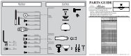
INSTALLATION INSTRUCTIONSMa r ra k e s h Unpacking: Before assembling and installing your ceiling fan, remove all parts from the shippingcartons and check them against the parts listed in instructions.Before discarding packaging material, be certain that all parts have been removed.Carton ContentsThe fan carton contains the fan body, warranty card, owner’smanual, and all the parts necessary to assemble and installyour <strong>Casablanca</strong> ceiling fan. These parts are shown at thestart of each installation section. Before you start, go throughthis Owner’s <strong>Manual</strong> and confirm that you have all the partsshown in each section.GETTING STARTEDCEILING HARDWAREBe sure to use only genuine <strong>Casablanca</strong> blades. The bladeshrink wrap holds 3 blades of matched weight. If more thanone fan is being installed, be sure not to mix blade sets.CAUTION: When removing the shrink wrap, be careful notto scratch the blades.CROSSBAR MOUNT-ING BRACKETWIRE NUT (4)additional hardware2 1 /4” x 8-32 roundedhead screw (2)1” x 8-32 roundedhead screw (2)FLAT WASHER (2)SUPPORT INSTALLATION PARTSLAG SCREW3/8” #7 X 5” (1)LARGEFLAT WASHER3/8” (1)CANOPY HARDWARECANOPYHATCHCANOPYCANOPY SCREW8-32 X 4 1 /8”(4)CANOPY LOCK WASHER#8 (4)getting started - continuedInstalling a New Ceiling Fixture Outlet BoxIf you do not have an existing fixture located where you wishto place your <strong>Casablanca</strong> fan, an approved ceiling fixtureoutlet box must be installed and wired.Warning: To reduce the risk of fire, electrical shock, orpersonal injury, mount to outlet box marked acceptablefor ceiling fan support.Using Existing Ceiling Fixture Outlet BoxAfter turning the power OFF at its source (either circuit breakeror fuse box), lower the old fixture and disconnect the wiring.Check the ceiling fixture outlet box to be sure that it is a ULlisted ceiling box for ceiling fan applications. If it is not, anew box must be installed.3
Crossbar Mounting Bracket INSTALLATIONNote: After removing the old fixture, check the outlet boxto insure that it is supported by a joist or beam across itsupper surface. If not, a 2” x 4” stud must be installed.JOISTStep 1. Remove the knockout plug in the center of the outletbox or drill a 1 /2″ hole for the lag screw to pass through.Then drill a 1 /4″ guide hole into the joist or beam to a depthof 3″.Step 2. Route the outlet box wires through the keyhole slot ofthe crossbar mounting bracket as shown. Attach the crossbarmounting bracket to outlet box with screws provided, assuringthat the outlet box wires are not pinched by the washer.CAUTION: To reduce the risk of personal injury,use only the mounting hardware provided withthe approved outlet box to install the crossbarmounting bracket.WARNING!SUPPORT DIRECTLY TOBUILDING STRUCTURE ONLY.ceiling fanapprovedwiring boxcrossbarmountingbracketflatwasherapprovedoutlet boxhardwareceilingwiringgreengroundwireridgesidedownStep 3. With the large washer attached, pass the lag screwthrough the center hole of the crosbar mounting bracketand screw into guide hole. Tighten until outlet box is firmlymounted to beam. This box must be firmly secured to theceiling. We recommend that the ceiling fixture outlet boxbe of sufficient capacity enabling it to support the weightof fan and light fixture under any conditions.LAG SCREW INSTALLATIONlagscrewLARGEWASHER4
canopy INSTALLATIONStep 4. Attach the canopy to the crossbar mounting bracket with three ofthe 8-32 x 4 1 /8” long canopy screws and lock washers provided with your<strong>Casablanca</strong> fan. Hand tighten until snug against the ceiling.Ma r ra k e s h Note: On sloped ceilings, align thecanopy opening toward the top orpeak of the room.FEED OUTLET BOXWIRES THROUGHCANOPY OPENINGcanopylockwashercanopyscrewblade holder, medallion and blade assemblyBlade(3)Blade Iron(3)Medallion(3)Bracket(3)8-32 x 8mm(12)Small Allen WrenchStep 5. Take a blade, blade iron, bracket and 4 of the 8-32screws. Align the blade iron into the holes of the blade andthen place a bracket (edges facing up, away from the blade)and assemble with the 4 screws. tighten securly by hand.5
Ma r ra k e s h Blade Assembly on <strong>Fan</strong> InstallationBlade AssemblyBladeholder screw12-24 x 5/8 (2 per blade)Step 10. Take a blade assembly and insert the foot of theblade iron between the motor adapter and the motor.Tip: The screw showing on the motor shouldbe between the 2 mounting holes for theblade iron.Step 11. Align one blade iron hole with the appropriate holein the motor and the cut-out in the the motor adapter. Tightenscrew by hand only.7
lade assembly on fan installationStep 12. Rotate blade assembly until the other blade ironhole aligns with the cut-out and again, install and tightenscrew by hand only. Repeat steps 11 and 12 until all 3 bladeassemblies are installed this way.Perma•lock HardwareALLEN SET SCREW1⁄ 4 -20 x 1 ⁄ 4 ”(pre-installed)3mmallen wrenchMOTOR COVER<strong>Fan</strong> preparation6” downrod& Ball assemblyimportant safety information!before before starting starting the the installation of of your your ceiling fan, fan, install the threaded downrod into the motor coupling and and lock lock the the assembly assemblyPrepare for fan installation as follows:Step 13. Place the motor cover on the downrod as shown.Step 14. Route the wires from the motor through thePerma•Lock downrod and ball assembly.Tip: The downrod has a tapered thread that is designedto lock completely when correctly installed.Step 15. Using the provided allen wrench, loosen the set screwseveral turns to allow installation of the downrod. Thread thedownrod into the motor coupling until it stops turning, thiswill take at least four and a half full turns.Step 16. Securely tighten the set screw with the providedallen wrench to ensure safe operation of your fan.ALLENSET SCREWmotorcouplingtaperedthreadMotor Covermotorwiresdownrod& BallassemblyCAUTION: Failure to fully lock in the downrodbefore securely tightening the allen setscrew may cause the fan to separate fromthe downrod during normal operation!8
Ve r s a•To u c h2 ®SAFEty firstWarning: To reduce the risk of electrical shock, this fan must be installed with anisolating wall control/switch.VERSA•TOUCH2 ♦ INSTALLATIONW-72controlW-72controlholder12v BAtteryDRYWALLANCHOR6-32 (2)woodscrew1” (2)screw6-32 X 3 /8”(2)screw6-32 X 1”(2)VERSA•TOUCH2 ♦ CONTROL BRACKET INSTALLATIONCAUTION! Do not use with wall dimmer.InnerMountingholescontrolbracketstandardtoggleswitchswitchcoverplateStandard Light SwitchStep A. Remove the two screws holding the switch coverplate. Do not remove the cover plate.Step B. Orient the control bracket as shown and line up thetwo inner mounting holes with those on the switch.Step C. Install and tighten screws by hand only.OuterMountingholescontrolbracketRockerTypeLightswitchswitchcoverplateRocker Light SwitchStep A. Break off the two tabs by pushing outward.Step B. Remove the two screws holding the switch coverplate. Do not remove the cover plate.Step C. Orient the control bracket as shown and line up thetwo inner mounting holes with those on the switch.Step D. Install and tighten screws by hand only.Wall InstallationStep A. Locate a 2x4wall stud in a convenientlocation.Step B. Orient the controlbracket as shown over the2x4 stud.Step C. Use the 1” woodscrews in either the inneror outer mounting holes.Install and tighten screwsby hand only.Changes or modifications not expresslyapproved in writing by <strong>Casablanca</strong> <strong>Fan</strong> Co.may void the user’s authority to operatethis equipment.12Note: The wall anchors and 6-32 x 1” screws may beused in situations where mounting to a stud is not possible.Use the inner mounting holes. After securing theanchor, discard the anchor’s pointed screws and use the6-32 decor ovalhead screws supplied.AnchorPanheadScrewwoodscrew 1”DRYWALL ANCHORDecor Ovalhead screw6-32 X 1”This device complies with RSS-210 of Industry Canada. Operation is subject tothe following two conditions: (1) this device may not cause interference, and(2) this device must accept any interference, including interference that maycause undesired operation of the device.
VERSA•TOUCH2 Operation<strong>Fan</strong> ControlSEND SIGNALTo start the fan. Press the selected speed button to run the fan at the desired speed. LEDLO=Low speed MED=Medium speed HI=High speedTo turn off the fan. Press the FAN OFF button.MEDAirflow DirectionTo reverse the airflow press the REVERSE button. Reverse operates at any speed whether fanis on or off. The fan returns to its set speed after reversing.LOLight ControlTurn the light on or off independently from the fan by pressing the LIGHT button. Keeppressing the button in excess of 0.7 seconds, it becomes a dimmer. The light varies from‘bright’ to ‘dim’ over approximately 8 seconds. This sequence will reverse the light when itreaches the brightest or dimmest level if you continue to hold the LIGHT button. Releasethe button when the desired level is reached.Memory FeatureThe last light function and fan speed will resume when power is turned back on.REVERSEAuto ResumeQuick (pressing less than 0.7 seconds) on/off operation of the LIGHT button maintains thedesired brightness level set previously.VERSA•TOUCH2 ♦ Changing FREQuency SETTINGNote: All fans leave the factory set to ‘00000’.You will only have to change the dip switch settings in the remote ifyou are using more than one fan in the same area and want to controlthem separately.Step 1. At the circuit breaker or fuse box, turn the power off for thefan you want to change.Step 2. Open the battery door of the Versa•Touch control and removethe batteries.Step 3. Change the dip switch settings, assuring that they are differentfrom the previously installed Versa•Touch fan.Step 4. Re-install the batteries and the battery door on the control.Step 5. At the circuit breaker or fuse box, turn the power back on forthe fan whose frequency you are changing.Step 6. Within 20 seconds of restoring power, push the Hi, Med, andLo buttons (in that order).Note: You may want to label your controls toassure you do not mix them up.WARNING: Do not turn the power off at the circuit breaker,then back on, for the previously installed Versa•Touch 2fan(s), as you may inadvertantly change the frequency settingsfor it as well.VERSA•TOUCH2 ♦ IF FAN DOES NOT WORKIf the fan is not functioning after installation:Step 1. Check to make sure that batteries are installed correctlyin the control.Step 2. Turn the power off to the fan (from the circuit breaker)for at least 5 seconds.Step 3. Turn the power back on (at the circuit breaker) and pushthe Hi, Med, and Low buttons–in that order–within 20 seconds.Step 4. The fan should now function properly.Ve r s a•To u c h2 ®WITHIN 20 SECONDS OF2TURNING THE FAN ON,PRESS IN THIS ORDER TOSET NEW FREQUENCY:1. HI2. MED3. LO 31Circuit breakeror fuse boxdip switchset to ‘10000’3LIGHTversa•touch 2control(back)dip switchset to ‘01001’PRESS IN THIS ORDER TO SET NEWFREQUENCY:1. HI 2. MED 3. LO2113HIFANSTOP
PROBLEM<strong>Fan</strong> will not starttroubleshooting tipsPlease refer to this troubleshooting guide before requesting service or contacting your dealer for assistance.<strong>Fan</strong> wobbles or shakes excessively<strong>Fan</strong> is noisy during operation<strong>Fan</strong> does not run on low speedBattery life is shortLight works, but fan does not work<strong>Fan</strong> and light run only on full speed<strong>Fan</strong> is missing one speed<strong>Fan</strong> does not change speed, but light worksReverse does not workPOSSIBLE REMEDIES• Check the main circuit fuses, circuit breakers, and wall switch position. Check all wireconnections. Make sure the power is turned off during this inspection.• The 9-pin connector is not making good contact. Check the 9-pin connector in the receivermounted in the switch housing.• The battery is weak. Install a fresh battery.• The fan receiver is defective. Replace fan receiver.• Check the frequency setting: Turn the power off at the circuit breaker, only for the fanthat is not functioning. Check that the jumper switches match in both the receiver andthe transmitter.• Be sure the canopy pin is set properly into the slot on the ball.• Check that the bladeholders have not been bent during installation and the blades arebalanced.• The hanger bracket and/or ceiling outlet are attached too loosely. Make sure the hangerbracket is attached tightly to the ceiling outlet box and the downrod assembly is securedfirmly.• The downrod is attached to downrod base too loosely. Make sure all the screws are securelytightened.• Check and tighten the light fixture retaining screws, glass shade screws, and/orlightbulb(s).• Tighten the canopy screws and mounting plate assembly. Make sure the wire nuts insidethe canopy and switch housing are not touching the metal parts and that they have notfallen off the wire splices. Tighten as necessary.• Tighten the blade holders to the flywheel (or direct drive motor) and the blades to thebladeholder screws.• Make sure all screws in the motor housing are snug but not overly tight.• If fan is new, it may need to be “broken in.” Run at high speed for several days.• Replace with alkaline batteries.• Pin connectors are not making good contact, check 9-pin connector under top cover.• The fan receiver is defective. Replace fan receiver.• The fan receiver is defective. Replace fan receiver.• The fan receiver is defective. Replace fan receiver.• The fan receiver is defective. Replace fan receiver.<strong>Fan</strong> starts working by itself • There is frequency interference. Change frequency as described on Page 13.<strong>Fan</strong> operates only when transmitter is close<strong>Fan</strong> works, but light does not dim<strong>Fan</strong> works, but light does not work• Check that antenna wire is not touching metal plate.• The fan receiver is defective. Replace fan receiver.• The fan receiver is defective. Replace fan receiver.• The light socket is broken. Replace socket.• A lightbulb is defective. Replace lightbulb.14
<strong>Fan</strong> FinishesMa r ra k e s h • For cleaning, a soft brush or lint-free cloth should be used to prevent scratching the finish.• A vacuum cleaner brush nozzle can remove heavier dust.Care Recommendations• Surface smudges or an accumulation of dirt and dust can be removed easily by using a mild detergent and slightly dampenedsoft cloth. An antistatic agent may be used, but never use abrasive cleaning agents as these will damage the finish.Blades• Wood-finish blades should be cleaned with a furniture polishing cloth. Occasionally, a light coat of furniture polish may beapplied for added protection and beauty.• For painted and high-gloss blades, surface smudges or an accumulation of dirt and dust can be removed easily by using amild detergent and slightly dampened soft cloth. An antistatic agent may be used, but never use abrasive cleaning agents asthese will damage the finish.No Need for Lubrication• Never lubricate this fan! The precision motor at the heart of your <strong>Casablanca</strong> fan features sealed bearings that are lubricatedfor life.• Do not attempt to oil the motor.Changing Lightbulbs• Be sure to turn the power to OFF at the wall switch or circuit breaker before changing lightbulbs.• Replace bulbs with the same type as you removed from the light fixture.• The maximum wattage rating for this fan's light kit is 100 watts.For questions or to locate the nearest <strong>Casablanca</strong> Authorized Service Center call toll free: 1-888-227-2178or visit us on the web at: www.casablancafanco.com1.This device complies with Part 15 of the FCC Rules.Operation is subject to the following two conditions: (1) this device may not cause harmfulinterference,and (2) this device must accept any interference received,including interference that may cause undesired operation.2.This equipment has been tested and found to comply with the limits for a Class B digital device, pursuant to Part 15 of the FCC Rules. Theselimits are designed to provide reasonable protection against harmful interference in a residential installation. This equipment generates,usesand can radiate radio frequency energy and,if not installed and used in accordance with the instructions,may cause harmful interference toradio communications. However,there is no guarantee that interference will not occur in a particular installation. If this equipment does causeharmful interference to radio or television reception,which can be determined by turning the equipment off and on,the user is encouraged totry to correct the interference by one or more of the following measures: Reorient or relocate the receiving antenna, Increase the separationbetween the equipment and receiver, Connect the equipment into an outlet on a circuit different from that to which the receiver is connected,Consult the dealer or an experienced radio/TV technician for help. Note: Any changes or modifications to the transmitter or receiver notexpressly approved by <strong>Casablanca</strong> <strong>Fan</strong> Company may void one’s authority to operate this remote control.Model Name:Model Number:Marrakesh TM89UXXMDimensions: A = 9.25"B = 20"NOTE: DimensionC = 4"B includes light fixtureand glass.D = 19.75"E = 5.6"Weight:40 lbs.Product SpecificationsMotor:188 x 20mm Direct DriveBlade Span: 64"Blade Iron Pitch: 14°No. of Blades: 3Technology: Versa•Touch2 ® W-72Optional Light Fixture: Exclusive KG89 Light Fixture(1) 100-watt halogen lightbulbAirflow:Electricity Use:Airflow Efficiency:7,900 cfm84 watts85 cfm/watt* Performance data is for fan only. No lighting wattage is included.15