CAR-14 Part 1 - Civil Aviation Authority of Nepal
CAR-14 Part 1 - Civil Aviation Authority of Nepal
CAR-14 Part 1 - Civil Aviation Authority of Nepal

Create successful ePaper yourself
Turn your PDF publications into a flip-book with our unique Google optimized e-Paper software.
CIVIL AVIATIIONREQUIREMENTS FORAERODROMES<strong>CAR</strong>-<strong>14</strong>, <strong>Part</strong> – IAerodrome Design and OperationsFirst Edition - 2012<strong>Civil</strong> <strong>Aviation</strong> <strong>Authority</strong> <strong>of</strong> <strong>Nepal</strong>
<strong>CAR</strong>-<strong>14</strong>AmendmentsAmendments and Corrigenda to these "<strong>Civil</strong> <strong>Aviation</strong> requirements for Aerodromes,<strong>Nepal</strong> are regularly issued by Director General <strong>of</strong> CAA, <strong>Nepal</strong>. The space below isprovided to keep a record <strong>of</strong> such amendments.No.RECORD OF AMENDMENTS AND CORRIGENDAAMENDMENTDATEAPPLICABLE1 st Edition Sept. 2012DATEENTEREDENTEREDBYNo.DATEAPPLICABLECORRIGENDADATEENTEREDENTEREDBYPage ii <strong>Civil</strong> <strong>Aviation</strong> <strong>Authority</strong> <strong>of</strong> <strong>Nepal</strong> September 2012
<strong>CAR</strong>-<strong>14</strong>TABLE OF CONTENTSPageCHAPTER 1.General............................................................................................................... 11.1 Definitions…………………………………………………………………..… 11.2 Applicability…………………………………………………………………… 91.3 Common reference systems…………………………………………………… 91.4 Certification <strong>of</strong> aerodromes…………………………………………………… 101.5 Safety management …………………………………………………………… 101.6 Airport design………………………………………………………………….. 101.7 Reference code………………………………………………………………… 10CHAPTER 2.Aerodrome data……………………………………………………………………. 122.1 Aeronautical data……………………………………………………………… 122.2 Aerodrome reference point……………………………………………………. 132.3 Aerodrome and runway elevations……………………………………………. 132.4 Aerodrome reference temperature…………………………………………….. <strong>14</strong>2.5 Aerodrome dimensions and related information……………………………… <strong>14</strong>2.6 Strength <strong>of</strong> pavements………………………………………………………… 152.7 Pre-flight altimeter check location……………………………………………. 172.8 Declared distances……………………………………………………………. 182.9 Condition <strong>of</strong> the movement area and related facilities……………………….. 182.10 Disabled aircraft removal……………………………………………………. 202.11 Rescue and fire fighting……………………………………………………… 202.12 Visual approach slope indicator systems……………………………………. 202.13 Coordination between aeronautical informationservices and aerodrome authorities………………………………………….. 21CHAPTER 3.Physical characteristics……………………………………………………………. 233.1 Runways……………………………………………………………………….. 233.2 Runway shoulders……………………………………………………………… 293.3 Runway turn pads……………………………………………………………… 303.4 Runway strips………………………………………………………………….. 323.5 Runway end safety areas………………………………………………………. 353.6 Clearways……………………………………………………………………… 373.7 Stopways ………………………………………………………………………. 383.8 Radio altimeter operating area…………………………………………………. 393.9 Taxiways……………………………………………………………………….. 393.10 Taxiway shoulders……………………………………………………………. 463.11 Taxiway strips………………………………………………………………… 463.12 Holding bays, runway-holding positions intermediate holding positionsAnd road-holding positions…………………………………………………………473.13 Aprons………………………………………………………………………... 493.<strong>14</strong> Isolated aircraft parking position……………………………………………... 503.15 De-Icing/Anti Icing Facilities............................................................................51Page iii <strong>Civil</strong> <strong>Aviation</strong> <strong>Authority</strong> <strong>of</strong> <strong>Nepal</strong> September 2012
<strong>CAR</strong>-<strong>14</strong>CHAPTER 4.Obstacle restriction and removal………………………………………………..… 534.1 Obstacle limitation surfaces…………………………………………………… 534.2 Obstacle limitation requirements……………………………………………... 594.3 Objects outside the obstacle limitation surfaces………………………………. 654.4 Other objects…………………………………………………………………… 65CHAPTER 5.Visual aids for navigation…………………………………………………………. 665.1 Indicators and signalling devices……………………………………………… 665.1.1 Wind direction indicators…………………………………………………… 665.1.2 Landing direction indicator…………………………………………………. 665.1.3 Signalling lamp……………………………………………………………… 675.1.4 Signal panels and signal area……………………………………………….. 675.2 Markings……………………………………………………………………… 685.2.1 General……………………………………………………………………… 685.2.2 Runway designation marking………………………………………………. 695.2.3 Runway centre line marking………………………………………………… 705.2.4 Threshold marking………………………………………………………….. 715.2.5 Aiming point marking ……………………………………………………… 735.2.6 Touchdown zone marking…………………………………………………... 755.2.7 Runway side stripe marking ………………………………………………… 775.2.8 Taxiway centre line marking………………………………………………… 775.2.9 Runway turn pad marking…………………………………………………… 805.2.10 Runway-holding position marking…………………………………………. 815.2.11 Intermediate holding position marking…………………………………….. 825.2.12 VOR aerodrome check-point marking …………………………………….. 835.2.13 Aircraft stand markings…………………………………………………….. 835.2.<strong>14</strong> Apron safety lines………………………………………………………….. 855.2.15 Road-holding position marking……………………………………………. 855.2.16 Mandatory instruction marking …………………………………………… 865.2.17 Information marking………………………………………………………. 875.3 Lights…………………………………………………………………………. 885.3.1 General……………………………………………………………………… 885.3.2 Emergency lighting…………………………………………………………. 925.3.3 Aeronautical beacons……………………………………………………….. 935.3.4 Approach lighting systems …………………………………………………. 945.3.5 Visual approach slope indicator systems…………………………………… 1035.3.6 Circling guidance lights…………………………………………………….. 1<strong>14</strong>5.3.7 Runway lead-in lighting systems……………………………………………. 1155.3.8 Runway threshold identification lights……………………………………… 1165.3.9 Runway edge lights ………………………………………………………… 1165.3.10 Runway threshold and wing bar lights……………………………………. 1175.3.11 Runway end lights…………………………………………………………. 1205.3.12 Runway centre line lights…………………………………………………. 1215.3.13 Runway touchdown zone lights…………………………………………… 1225.3.<strong>14</strong> Rapid exit taxiway indicator lights………………………………………… 1235.3.15 Stopway lights……………………………………………………………... 1265.3.16 Taxiway centre line lights…………………………………………………. 1265.3.17 Taxiway edge lights……………………………………………………….. 1325.3.18 Runway turn pad lights……………………………………………………. 133Page iv <strong>Civil</strong> <strong>Aviation</strong> <strong>Authority</strong> <strong>of</strong> <strong>Nepal</strong> September 2012
<strong>CAR</strong>-<strong>14</strong>5.3.19 Stop bars…………………………………………………………………… 1345.3.20 Intermediate holding position lights……………………………………….. 1365.3.21 De-Icing / Anti Icing Facility Exit Light.....……………………………….. 1375.3.22 Runway guard lights……………………………………………………….. 1375.3.23 Apron floodlighting………………………………………………………… <strong>14</strong>05.3.24 Visual docking guidance system…………………………………………… <strong>14</strong>15.3.25 Advanced visual docking guidance system………………………………… <strong>14</strong>35.3.26 Aircraft stand manoeuvring guidance lights……………………………….. <strong>14</strong>55.3.27 Road-holding position light………………………………………………… <strong>14</strong>65.4 Signs……………………………………………………………………………..<strong>14</strong>75.4.1 General……………………………………………………………………… <strong>14</strong>75.4.2 Mandatory instruction signs………………………………………………… 1515.4.3 Information signs…………………………………………………………… 1545.4.4 VOR aerodrome check-point sign………………………………………….. 1575.4.5 Aerodrome identification sign……………………………………………… 1595.4.6 Aircraft stand identification signs………………………………………….. 1595.4.7 Road-holding position sign…………………………………………………. 1595.5 Markers……………………………………………………………………….. 1605.5.1 General……………………………………………………………………… 1605.5.2 Unpaved runway edge markers…………………………………………….. 1605.5.3 Stopway edge markers……………………………………………………… 1605.5.4 Edge markers for snow-covered runways.................................................... 1615.5.5 Taxiway edge markers……………………………………………………… 1615.5.6 Taxiway centre line markers……………………………………………….. 1625.5.7 Unpaved taxiway edge markers…………………………………………….. 1625.5.8 Boundary markers…………………………………………………………… 163CHAPTER 6.Visual aids for denoting obstacles………………………………………………… 1646.1 Objects to be marked and/or lighted………………………………………….. 1646.2 Marking <strong>of</strong> objects ……………………………………………………………. 1666.3 Lighting <strong>of</strong> objects ……………………………………………………………. 1706.4 Wind turbines .................................................................................................. 176CHAPTER 7.Visual aids for denoting restricted use areas……………………………………… 1777.1 Closed runways and taxiways, or parts there<strong>of</strong> ……………………………… 1777.2 Non-load-bearing surfaces……………………………………………………. 1777.3 Pre-threshold area…………………………………………………………….. 1787.4 Unserviceable areas…………………………………………………………… 178CHAPTER 8.Electrical systems………………………………………………………………… 1818.1 Electrical power supply systems for air navigation facilities………………… 1818.2 System design………………………………………………………………… 1838.3 Monitoring……………………………………………………………………. 183CHAPTER 9.Aerodrome operational services, equipment and installations……………………. 1859.1 Aerodrome emergency planning………………………………………………. 1859.2 Rescue and fire fighting ………………………………………………………. 187Page v <strong>Civil</strong> <strong>Aviation</strong> <strong>Authority</strong> <strong>of</strong> <strong>Nepal</strong> September 2012
<strong>CAR</strong>-<strong>14</strong>9.3 Disabled aircraft removal……………………………………………………… 1949.4 Wildlife strike hazard reduction………………………………………………. 1949.5 Apron management service……………………………………………………. 1959.6 Ground servicing <strong>of</strong> aircraft…………………………………………………… 1969.7 Aerodrome vehicle operations…………………………………………………. 1969.8 Surface movement guidance and control systems …………………………… . 1979.9 Siting <strong>of</strong> equipment and installations on operational areas…………………… 1989.10 Fencing……………………………………………………………………….. 2009.11 Security lighting ……………………………………………………………… 200CHAPTER 10.Aerodrome maintenance…………………………………………………………… 20110.1 General……………………………………………………………………….. 20110.2 Pavements ……………………………………………………………………. 20110.3 Runway pavement overlays ………………………………………………….. 20310.4 Visual aids ……………………………………………………………………. 203APPENDIX 1.Colours for aeronautical ground lights,markings, signs and panels………………. 2071. General………………………………………………………………………….. 2072. Colours for aeronautical ground lights…………………………………………. 2073. Colours for markings, signs and panels………………………………………… 209APPENDIX 2.Aeronautical ground light characteristics…………………………………………...217APPENDIX 3.Mandatory instruction markings and information markings………………………. 243APPENDIX 4. Requirements concerning design <strong>of</strong> taxiing guidance signs………. 249APPENDIX 5.Aeronautical data quality requirements……………………………………………..261APPENDIX 6.Location <strong>of</strong> lights on obstacles……………………………………………………. 265APPENDIX 7.Framework for safety management systems (SMS) …………………………. 273ATTACHMENT A.Guidance material supplementary to <strong>CAR</strong> - <strong>14</strong>, <strong>Part</strong> 1………………………… 2761. Number, siting and orientation <strong>of</strong> runways……………………………………… 2762. Clearways and stopways ……………………………………………………… 2773. Calculation <strong>of</strong> declared distances………………………………………………...2794. Slopes on a runway……………………………………………………………… 2805. Runway surface evenness ………………………………………………………. 282Page vi <strong>Civil</strong> <strong>Aviation</strong> <strong>Authority</strong> <strong>of</strong> <strong>Nepal</strong> September 2012
<strong>CAR</strong>-<strong>14</strong>6. Determining and expressing the friction characteristics <strong>of</strong>Snow and Ice Covered paved Surface .......................................................... 2837. Determination <strong>of</strong> friction characteristics <strong>of</strong> wet paved runways……………….. 2868. Strips……………………………………………………………………………. 2889. Runway end safety areas………………………………………………………… 29010. Location <strong>of</strong> threshold…………………………………………………………. 29011. Approach lighting systems…………………………………………………….. 29112. Priority <strong>of</strong> installation <strong>of</strong> visual approach slope indicator systems……………. 29913. Lighting <strong>of</strong> unserviceable areas……………………………………………….. 300<strong>14</strong>. Rapid exit taxiway indicator lights……………………………………………. 30015. Intensity control <strong>of</strong> approach and runway lights ……………………………… 30016. Signal area …………………………………………………………………...... 30117. Rescue and fire fighting services………………………………………………. 30118. Operators <strong>of</strong> vehicles………………………………………………………...... 30419. The ACN-PCN method <strong>of</strong> reporting pavement strength…………………….... 304ATTACHMENT B.Obstacle limitation surfaces……………………………………………………….. 306ATTACHMENT C.Framework for the State safety programme (SSP)………………………………… 307Page vii <strong>Civil</strong> <strong>Aviation</strong> <strong>Authority</strong> <strong>of</strong> <strong>Nepal</strong> September 2012
<strong>CAR</strong>-<strong>14</strong>ABBREVIATIONS AND SYMBOLSAbbreviationsACN - Aircraft classification numberaprx - ApproximatelyASDA - Accelerate-stop distance availableATS - Air traffic servicescd - CandelaC - Degree CelsiusCBR - California bearing ratioCIE - Commission Internationale de l’Éclairagecm - CentimetreDME - Distance measuring equipmentft- FootILS - Instrument landing systemIMC - Instrument meteorological conditionsK - Degree Kelvinkg - Kilogramkm - Kilometrekm/h - Kilometre per hourkt - KnotL – LitreLDA - Landing distance availablem – Metre<strong>CAR</strong>-<strong>14</strong> – <strong>Civil</strong> <strong>Aviation</strong> requirements for Aerodromess, <strong>Nepal</strong>max – Maximummm – MillimetrePage viii <strong>Civil</strong> <strong>Aviation</strong> <strong>Authority</strong> <strong>of</strong> <strong>Nepal</strong> September 2012
<strong>CAR</strong>-<strong>14</strong>mnm - MinimumMN - MeganewtonMPa - MegapascalNM - Nautical mileNU - Not usableOCA/H - Obstacle clearance altitude/heightOFZ - Obstacle free zonePCN - Pavement classification numberRESA - Runway end safety areaRVR - Runway visual rangeTODA - Take-<strong>of</strong>f distance availableTORA - Take-<strong>of</strong>f run availableVMC - Visual meteorological conditionsVOR - Very high frequency omnidirectional radio rangePage ix <strong>Civil</strong> <strong>Aviation</strong> <strong>Authority</strong> <strong>of</strong> <strong>Nepal</strong> September 2012
<strong>CAR</strong>-<strong>14</strong>Symbols° Degree= Equals'Minute <strong>of</strong> arcµ Friction coefficient> Greater than< Less than% Percentage± Plus or minusPage x <strong>Civil</strong> <strong>Aviation</strong> <strong>Authority</strong> <strong>of</strong> <strong>Nepal</strong> September 2012
<strong>CAR</strong>-<strong>14</strong>Amendments to <strong>CAR</strong>-<strong>14</strong>, Volume-IAmendment Source(s) Subject(s)EffectiveDate<strong>CAR</strong>-<strong>14</strong>,<strong>Part</strong> 1,1stEditionAnnex-<strong>14</strong>,Fifth Edition-2009Definitions <strong>of</strong> instrument runway and obstacle;certification <strong>of</strong> aerodromes; aerodrome data; enhancedtaxiway centre line marking; mandatory instructionmarking; taxiway edge lights; advanced visual dockingguidance system; mandatory instruction signs; markingand lighting <strong>of</strong> wind turbines; public healthemergencies in aerodrome emergency planning, rescueand fire fighting; wildlife strike hazard reduction;pavement monitoring and maintenance; chromaticityand luminance factors <strong>of</strong> green colour in Appendix 1;notes to Figures A2-9 and A2-10 for isocandeladiagrams for runway edge lights in Appendix 2; NOENTRY sign in Figure A4-2 in Appendix 4; guidanceon runway surface evenness, location <strong>of</strong> displacedthreshold and rescue and fire fighting in Attachment A.Sept. 2012Safety management; Appendix 7, Framework forSafety Management Systems (SMS); Attachment C,Framework for the State Safety Programme (SSP).Page xi <strong>Civil</strong> <strong>Aviation</strong> <strong>Authority</strong> <strong>of</strong> <strong>Nepal</strong> September 2012
FOREWORDPursuant to Clause -5 Sub-Clause "Pha" and Clause- 35 <strong>of</strong> <strong>Civil</strong> <strong>Aviation</strong> <strong>Authority</strong> <strong>of</strong><strong>Nepal</strong> Act, 2053 (1996) and Rule-82, Schedule-3 <strong>of</strong> <strong>Civil</strong> <strong>Aviation</strong> Regulation, 2058(2002), this "<strong>Civil</strong> <strong>Aviation</strong> Requirements for Aerodromes" referred here-in-after as the"<strong>CAR</strong> – <strong>14</strong>, <strong>Part</strong> 1" have been enacted by <strong>Civil</strong> <strong>Aviation</strong> <strong>Authority</strong> <strong>of</strong> <strong>Nepal</strong> inaccordance with the Standard and Recommended Practices <strong>of</strong> "Annex -<strong>14</strong> Aerodromes,Volume 1 Aerodrome design and Operations" to the Convention <strong>of</strong> International <strong>Civil</strong><strong>Aviation</strong> for safety, regularity or efficiency <strong>of</strong> International <strong>Civil</strong> <strong>Aviation</strong> in <strong>Nepal</strong>. This<strong>CAR</strong>-<strong>14</strong>, <strong>Part</strong> 1 is a national standards for design and operation <strong>of</strong> aerodrome in <strong>Nepal</strong>.This "<strong>Civil</strong> <strong>Aviation</strong> Requirements for Aerodromes"(<strong>CAR</strong>-<strong>14</strong>, <strong>Part</strong> 1) comes into forcefrom September, 2012 and supersedes previous "Manual <strong>of</strong> Aerodrome Standards <strong>of</strong><strong>Nepal</strong>, Volume 1" 1 st Edition 2008.…………………………. September, 2012Director General<strong>Civil</strong> <strong>Aviation</strong> <strong>Authority</strong> <strong>of</strong> <strong>Nepal</strong>Babar Mahal, Kathmandu, <strong>Nepal</strong>
<strong>CAR</strong>-<strong>14</strong>CHAPTER- 1GENERAL1.1 DefinitionsWhen the following terms are used in this <strong>CAR</strong>-<strong>14</strong>, they have the following meanings:Accuracy. A degree <strong>of</strong> conformance between the estimated or measured value and thetrue value.Note.— For measured positional data, the accuracy is normally expressed in terms <strong>of</strong> adistance from a stated position within which there is a defined confidence <strong>of</strong> the trueposition falling.Aerodrome. A defined area on land or water (including any buildings, installations andequipment) intended to be used either wholly or in part for the arrival, departure andsurface movement <strong>of</strong> aircraft.Aerodrome beacon. Aeronautical beacon used to indicate the location <strong>of</strong> an aerodromefrom the air.Aerodrome certificate. A certificate issued by the appropriate authority under applicableregulations for the operation <strong>of</strong> an aerodrome.Aerodrome elevation. The elevation <strong>of</strong> the highest point <strong>of</strong> the landing area.Aerodrome identification sign. A sign placed on an aerodrome to aid in identifying theaerodrome from the air.Aerodrome reference point. The designated geographical location <strong>of</strong> an aerodrome.Aerodrome traffic density.a) Light. Where the number <strong>of</strong> movements in the mean busy hour is not greater than 15per runway or typically less than 20 total aerodrome movements.b) Medium. Where the number <strong>of</strong> movements in the mean busy hour is <strong>of</strong> the order <strong>of</strong> 16to 25 per runway or typically between 20 to 35 total aerodrome movements.c) Heavy. Where the number <strong>of</strong> movements in the mean busy hour is <strong>of</strong> the order <strong>of</strong> 26 ormore per runway or typically more than 35 total aerodrome movements.Note 1.— The number <strong>of</strong> movements in the mean busy hour is the arithmetic mean overthe year <strong>of</strong> the number <strong>of</strong> movements in the daily busiest hour.Note 2.— Either a take-<strong>of</strong>f or a landing constitutes a movement.Aeronautical beacon. An aeronautical ground light visible at all azimuths, eithercontinuously or intermittently, to designate a particular point on the surface <strong>of</strong> the earth.Aeronautical ground light. Any light specially provided as an aid to air navigation, otherthan a light displayed on an aircraft.Aeroplane reference field length. The minimum field length required for take-<strong>of</strong>f atmaximum certificated take-<strong>of</strong>f mass, sea level, standard atmospheric conditions, still airand zero runway slope, as shown in the appropriate aeroplane flight manual prescribed byPage 1 <strong>Civil</strong> <strong>Aviation</strong> <strong>Authority</strong> <strong>of</strong> <strong>Nepal</strong> September 2012
<strong>CAR</strong>-<strong>14</strong>the certificating authority or equivalent data from the aeroplane manufacturer. Fieldlength means balanced field length for aeroplanes, if applicable, or take-<strong>of</strong>f distance inother cases.Note.— Attachment A, Section 2 provides information on the concept <strong>of</strong> balanced fieldlength and the Airworthiness Manual (Doc 9760) contains detailed guidance on mattersrelated to take-<strong>of</strong>f distance.Aircraft classification number (ACN). A number expressing the relative effect <strong>of</strong> anaircraft on a pavement for a specified standard subgrade category.Note.— The aircraft classification number is calculated with respect to the center <strong>of</strong>gravity (CG) position which yields the critical loading on the critical gear. Normally theaftmost CG position appropriate to the maximum gross apron (ramp) mass is used tocalculate the ACN. In exceptional cases the forwardmost CG position may result in thenose gear loading being more critical.Aircraft stand. A designated area on an apron intended to be used for parking an aircraft.Apron. A defined area, on a land aerodrome, intended to accommodate aircraft forpurposes <strong>of</strong> loading or unloading passengers, mail or cargo, fuelling, parking ormaintenance.Apron management service. A service provided to regulate the activities and themovement <strong>of</strong> aircraft and vehicles on an apron.Balked landing. A landing manoeuvre that is unexpectedly discontinued at any pointbelow the obstacle clearance altitude/height (OCA/H).Barrette. Three or more aeronautical ground lights closely spaced in a transverse line sothat from a distance they appear as a short bar <strong>of</strong> light.Calendar. Discrete temporal reference system that provides the basis for definingtemporal position to a resolution <strong>of</strong> one day (ISO 19108*).Capacitor discharge light. A lamp in which high-intensity flashes <strong>of</strong> extremely shortduration are produced by the discharge <strong>of</strong> electricity at high voltage through a gasenclosed in a tube.Certified aerodrome. An aerodrome whose operator has been granted an aerodromecertificate.Clearway. A defined rectangular area on the ground or water under the control <strong>of</strong> theappropriate authority, selected or prepared as a suitable area over which an aeroplane maymake a portion <strong>of</strong> its initial climb to a specified height.Cyclic redundancy check (CRC). A mathematical algorithm applied to the digitalexpression <strong>of</strong> data that provides a level <strong>of</strong> assurance against loss or alteration <strong>of</strong> data.______________________* ISO Standard 19108, Geographic Information-Temporal schemaPage 2 <strong>Civil</strong> <strong>Aviation</strong> <strong>Authority</strong> <strong>of</strong> <strong>Nepal</strong> September 2012
<strong>CAR</strong>-<strong>14</strong>Data quality. A degree or level <strong>of</strong> confidence that the data provided meet therequirements <strong>of</strong> the data user in terms <strong>of</strong> accuracy, resolution and integrity.Datum. Any quantity or set <strong>of</strong> quantities that may serve as a reference or basis for thecalculation <strong>of</strong> other quantities (ISO 19104**).De-icing/anti-icing facility. A facility where frost, ice or snow is removed (de-icing)from the aeroplane to provide clean surfaces, and/or where clean surfaces <strong>of</strong> the aeroplanereceive protection (anti-icing) against the formation <strong>of</strong> frost or ice and accumulation <strong>of</strong>snow or slush for a limited period <strong>of</strong> time.Note.— Further guidance is given in the Manual <strong>of</strong> Aircraft Ground De-icing/Anti-icingOperations (Doc 9640).De-icing/anti-icing pad. An area comprising an inner area for the parking <strong>of</strong> an aeroplaneto receive de-icing/anti-icing treatment and an outer area for the manoeuvring <strong>of</strong> two ormore mobile de-icing/anti-icing equipment.Declared distances.a) Take-<strong>of</strong>f run available (TORA). The length <strong>of</strong> runway declared available and suitablefor the ground run <strong>of</strong> an aeroplane taking <strong>of</strong>f.b) Take-<strong>of</strong>f distance available (TODA). The length <strong>of</strong> the take-<strong>of</strong>f run available plus thelength <strong>of</strong> the clearway, if provided.c) Accelerate-stop distance available (ASDA). The length <strong>of</strong> the take-<strong>of</strong>f run availableplus the length <strong>of</strong> the stopway, if provided.d) Landing distance available (LDA). The length <strong>of</strong> runway which is declared availableand suitable for the ground run <strong>of</strong> an aeroplane landing.Dependent parallel approaches. Simultaneous approaches to parallel or near-parallelinstrument runways where radar separation minima between aircraft on adjacent extendedrunway centre lines are prescribed.Displaced threshold. A threshold not located at the extremity <strong>of</strong> a runway.Effective intensity. The effective intensity <strong>of</strong> a flashing light is equal to the intensity <strong>of</strong> afixed light <strong>of</strong> the same colour which will produce the same visual range under identicalconditions <strong>of</strong> observation.Ellipsoid height (Geodetic height). The height related to the reference ellipsoid,measured along the ellipsoidal outer normal through the point in question.Fixed light. A light having constant luminous intensity when observed from a fixed point.Frangible object. An object <strong>of</strong> low mass designed to break, distort or yield on impact soas to present the minimum hazard to aircraft.Note.— Guidance on design for frangibility is contained in the Aerodrome DesignManual (Doc 9157), <strong>Part</strong> 6.________________________** ISO Standard 19104, Geographic Information-TerminologyPage 3 <strong>Civil</strong> <strong>Aviation</strong> <strong>Authority</strong> <strong>of</strong> <strong>Nepal</strong> September 2012
<strong>CAR</strong>-<strong>14</strong>Geodetic datum. A minimum set <strong>of</strong> parameters required to define location and orientation<strong>of</strong> the local reference system with respect to the global reference system/frame.Geoid. The equipotential surface in the gravity field <strong>of</strong> the earth which coincides with theundisturbed mean sea level (MSL) extended continuously through the continents.Note.— The geoid is irregular in shape because <strong>of</strong> local gravitational disturbances (windtides, salinity, current, etc.) and the direction <strong>of</strong> gravity is perpendicular to the geoid atevery point.Geoid undulation. The distance <strong>of</strong> the geoid above (positive) or below (negative) themathematical reference ellipsoid.Note.— In respect to the World Geodetic System — 1984 (WGS-84) defined ellipsoid, thedifference between the WGS- 84 ellipsoidal height and orthometric height representsWGS-84 geoid undulation.Gregorian calendar. Calendar in general use; first introduced in 1582 to define a yearthat more closely approximates the tropical year than the Julian calendar (ISO 19108***).Note.— In the Gregorian calendar, common years have 365 days and leap years 366 daysdivided into twelve sequential months.Hazard beacon. An aeronautical beacon used to designate a danger to air navigation.Heliport. An aerodrome or a defined area on a structure intended to be used wholly or inpart for the arrival, departure and surface movement <strong>of</strong> helicopters.Holding bay. A defined area where aircraft can be held, or bypassed, to facilitate efficientsurface movement <strong>of</strong> aircraft.Holdover time. The estimated time the anti-icing fluid (treatment) will prevent theformation <strong>of</strong> ice and frost and the accumulation <strong>of</strong> snow on the protected (treated)surfaces <strong>of</strong> an aeroplane.Human Factors principles. Principles which apply to aeronautical design, certification,training, operations and maintenance and which seek safe interface between the humanand other system components by proper consideration to human performance.Human performance. Human capabilities and limitations which have an impact on thesafety and efficiency <strong>of</strong> aeronautical operations.Identification beacon. An aeronautical beacon emitting a coded signal by means <strong>of</strong>which a particular point <strong>of</strong> reference can be identified.Independent parallel approaches. Simultaneous approaches to parallel or near-parallelinstrument runways where radar separation minima between aircraft on adjacent extendedrunway centre lines are not prescribed.Independent parallel departures. Simultaneous departures from parallel or near-parallelinstrument runways._______________________*** ISO Standard 19108, Geographic Information-Temporal schemaPage 4 <strong>Civil</strong> <strong>Aviation</strong> <strong>Authority</strong> <strong>of</strong> <strong>Nepal</strong> September 2012
<strong>CAR</strong>-<strong>14</strong>Instrument runway. One <strong>of</strong> the following types <strong>of</strong> runways intended for the operation <strong>of</strong>aircraft using instrument approach procedures:a) Non-precision approach runway. An instrument runway served by visual aids and anon-visual aid providing at least directional guidance adequate for a straight-in approach.b) Precision approach runway, category I. An instrument runway served by ILS and/orMLS and visual aids intended for operations with a decision height not lower than 60 m(200 ft) and either a visibility not less than 800 m or a runway visual range not less than550 m.c) Precision approach runway, category II. An instrument runway served by ILS and/orMLS and visual aids intended for operations with a decision height lower than 60 m (200ft) but not lower than 30 m (100 ft) and a runway visual range not less than 300m.d) Precision approach runway, category III. An instrument runway served by ILS and/orMLS to and along the surface <strong>of</strong> the runway and:A — intended for operations with a decision height lower than 30 m (100 ft), or nodecision height and a runway visual range not less than 175m.B — intended for operations with a decision height lower than 15 m (50 ft), or nodecision height and a runway visual range less than 175m but not less than 50 m.C — intended for operations with no decision height and no runway visual rangelimitations.Note 1.— See Annex 10, <strong>Part</strong> 1 for related ILS and/or MLS specifications.Note 2.— Visual aids need not necessarily be matched to the scale <strong>of</strong> non-visual aidsprovided. The criterion for the selection <strong>of</strong> visual aids is the conditions in whichoperations are intended to be conducted.Integrity (aeronautical data). A degree <strong>of</strong> assurance that an aeronautical data and itsvalue has not been lost nor altered since the data origination or authorized amendment.Intermediate holding position. A designated position intended for traffic control at whichtaxiing aircraft and vehicles shall stop and hold until further cleared to proceed, when soinstructed by the aerodrome control tower.Landing area. That part <strong>of</strong> a movement area intended for the landing or take-<strong>of</strong>f <strong>of</strong>aircraft.Landing direction indicator. A device to indicate visually the direction currentlydesignated for landing and for take-<strong>of</strong>f.Laser-beam critical flight zone (LCFZ). Airspace in the proximity <strong>of</strong> an aerodrome butbeyond the LFFZ where the irradiance is restricted to a level unlikely to cause glareeffects.Laser-beam free flight zone (LFFZ). Airspace in the immediate proximity to theaerodrome where the irradiance is restricted to a level unlikely to cause any visualdisruption.Laser-beam sensitive flight zone (LSFZ). Airspace outside, and not necessarilycontiguous with, the LFFZ and LCFZ where the irradiance is restricted to a level unlikelyto cause flash-blindness or after-image effects.Page 5 <strong>Civil</strong> <strong>Aviation</strong> <strong>Authority</strong> <strong>of</strong> <strong>Nepal</strong> September 2012
<strong>CAR</strong>-<strong>14</strong>Lighting system reliability. The probability that the complete installation operates withinthe specified tolerances and that the system is operationally usable.Manoeuvring area. That part <strong>of</strong> an aerodrome to be used for the take-<strong>of</strong>f, landing andtaxiing <strong>of</strong> aircraft, excluding aprons.Marker. An object displayed above ground level in order to indicate an obstacle ordelineate a boundary.Marking. A symbol or group <strong>of</strong> symbols displayed on the surface <strong>of</strong> the movement areain order to convey aeronautical information.Movement area. That part <strong>of</strong> an aerodrome to be used for the take-<strong>of</strong>f, landing andtaxiing <strong>of</strong> aircraft, consisting <strong>of</strong> the manoeuvring area and the apron(s).Near-parallel runways. Non-intersecting runways whose extended centre lines have anangle <strong>of</strong> convergence/divergence <strong>of</strong> 15 degrees or less.Non-instrument runway. A runway intended for the operation <strong>of</strong> aircraft using visualapproach procedures.Normal flight zone (NFZ). Airspace not defined as LFFZ, LCFZ or LSFZ but whichmust be protected from laser radiation capable <strong>of</strong> causing biological damage to the eye.Obstacle. All fixed (whether temporary or permanent) and mobile objects, or partsthere<strong>of</strong>, that:a) are located on an area intended for the surface movement <strong>of</strong> aircraft; orb) extend above a defined surface intended to protect aircraft in flight; orc) stand outside those defined surfaces and that have been assessed as being a hazard toair navigation.Obstacle free zone (OFZ). The airspace above the inner approach surface, innertransitional surfaces, and balked landing surface and that portion <strong>of</strong> the strip bounded bythese surfaces, which is not penetrated by any fixed obstacle other than a low-mass andfrangibly mounted onerequired for air navigation purposes.Orthometric height. Height <strong>of</strong> a point related to the geoid, generally presented as an MSLelevation.Pavement classification number (PCN). A number expressing the bearing strength <strong>of</strong> apavement for unrestricted operations.Precision approach runway, see Instrument runway.Primary runway(s). Runway(s) used in preference to others whenever conditions permit.Protected flight zones. Airspace specifically designated to mitigate the hazardous effects<strong>of</strong> laser radiation.Page 6 <strong>Civil</strong> <strong>Aviation</strong> <strong>Authority</strong> <strong>of</strong> <strong>Nepal</strong> September 2012
<strong>CAR</strong>-<strong>14</strong>Road. An established surface route on the movement area meant for the exclusive use <strong>of</strong>vehicles.Road-holding position. A designated position at which vehicles may be required to hold.Runway. A defined rectangular area on a land aerodrome prepared for the landing andtake-<strong>of</strong>f <strong>of</strong> aircraft.Runway end safety area (RESA). An area symmetrical about the extended runway centreline and adjacent to the end <strong>of</strong> the strip primarily intended to reduce the risk <strong>of</strong> damage toan aeroplane undershooting or overrunning the runway.Runway guard lights. A light system intended to caution pilots or vehicle drivers thatthey are about to enter an active runway.Runway-holding position. A designated position intended to protect a runway, anobstacle limitation surface, or an ILS/ MLS critical/sensitive area at which taxiing aircraftandvehicles shall stop and hold, unless otherwise authorized by the aerodrome control tower.Note.— In radiotelephony phraseologies, the expression “holding point” is used todesignate the runway-holding position.Runway strip. A defined area including the runway and stopway, if provided, intended:a) to reduce the risk <strong>of</strong> damage to aircraft running <strong>of</strong>f a runway; andb) to protect aircraft flying over it during take-<strong>of</strong>f or landing operations.Runway turn pad. A defined area on a land aerodrome adjacent to a runway for thepurpose <strong>of</strong> completing a 180-degree turn on a runway.Runway visual range (RVR). The range over which the pilot <strong>of</strong> an aircraft on the centreline <strong>of</strong> a runway can see the runway surface markings or the lights delineating the runwayor identifying its centre line.Safety programme. An integrated set <strong>of</strong> regulations and activities aimed at improvingsafety.Safety management system. A systematic approach to managing safety including thenecessary organizational structure, accountabilities, policies and procedures.Segregated parallel operations. Simultaneous operations on parallel or near-parallelinstrument runways in which one runway is used exclusively for approaches and the otherrunway is used exclusively for departures.Shoulder. An area adjacent to the edge <strong>of</strong> a pavement so prepared as to provide atransition between the pavement and the adjacent surface.Sign.a) Fixed message sign. A sign presenting only one message.Page 7 <strong>Civil</strong> <strong>Aviation</strong> <strong>Authority</strong> <strong>of</strong> <strong>Nepal</strong> September 2012
<strong>CAR</strong>-<strong>14</strong>b) Variable message sign. A sign capable <strong>of</strong> presenting several pre-determined messagesor no message, as applicable.Signal area. An area on an aerodrome used for the display <strong>of</strong> ground signals.Slush. Water-saturated snow which with a heel-and-toe slap down motion against theground will be displaced with a splatter; specific gravity: 0.5 up to 0.8.Note.— Combinations <strong>of</strong> ice, snow and/or standing water may, especially when rain, rainand snow, or snow is falling, produce substances with specific gravities in excess <strong>of</strong> 0.8.These substances, due to their high water/ice content, will have a transparent rather thana cloudy appearance and, at the higher specific gravities, will be readily distinguishablefrom slush.Snow (on the ground).a) Dry snow. Snow which can be blown if loose or, if compacted by hand, will fallapart again upon release; specific gravity: up to but not including 0.35.b) Wet snow. Snow which, if compacted by hand, will stick together and tend to orform a snowball; specific gravity: 0.35 up to but not including 0.5.c) Compacted snow. Snow which has been compressed into a solid mass that resistsfurther compression and will hold together or break up into lumps if picked up;specific gravity: 0.5 and over.Station declination. An alignment variation between the zero degree radial <strong>of</strong> a VOR andtrue north, determined at the time the VOR station is calibrated.Stopway. A defined rectangular area on the ground at the end <strong>of</strong> take-<strong>of</strong>f run availableprepared as a suitable area in which an aircraft can be stopped in the case <strong>of</strong> anabandoned take <strong>of</strong>f.Switch-over time (light). The time required for the actual intensity <strong>of</strong> a light measured ina given direction to fall from 50 per cent and recover to 50 per cent during a power supplychangeover, when the light is being operated at intensities <strong>of</strong> 25 per cent or above.Take-<strong>of</strong>f runway. A runway intended for take-<strong>of</strong>f only.Taxiway. A defined path on a land aerodrome established for the taxiing <strong>of</strong> aircraft andintended to provide a link between one part <strong>of</strong> the aerodrome and another, including:a) Aircraft stand taxilane. A portion <strong>of</strong> an apron designated as a taxiway andintended to provide access to aircraft stands only.b) Apron taxiway. A portion <strong>of</strong> a taxiway system located on an apron and intended toprovide a through taxi route across the apron.c) Rapid exit taxiway. A taxiway connected to a runway at an acute angle anddesigned to allow landing aeroplanes to turn <strong>of</strong>f at higher speeds than are achievedon other exit taxiways thereby minimizing runway occupancy times.Taxiway intersection. A junction <strong>of</strong> two or more taxiways.Page 8 <strong>Civil</strong> <strong>Aviation</strong> <strong>Authority</strong> <strong>of</strong> <strong>Nepal</strong> September 2012
<strong>CAR</strong>-<strong>14</strong>Taxiway strip. An area including a taxiway intended to protect an aircraft operating onthe taxiway and to reduce the risk <strong>of</strong> damage to an aircraft accidentally running <strong>of</strong>f thetaxiway.Threshold. The beginning <strong>of</strong> that portion <strong>of</strong> the runway usable for landing.Touchdown zone. The portion <strong>of</strong> a runway, beyond the threshold, where it is intendedlanding aeroplanes first contact the runway.Usability factor. The percentage <strong>of</strong> time during which the use <strong>of</strong> a runway or system <strong>of</strong>runways is not restricted because <strong>of</strong> the cross-wind component.Note.— Cross-wind component means the surface wind component at right angles to therunway centre line.1.2 Applicability1.2.1 The specifications specified in this <strong>CAR</strong>-<strong>14</strong> shall apply to all civil aerodromes opento public use in <strong>Nepal</strong>. The specifications in the chapter 3 shall apply only to landaerodromes. The specifications in the <strong>CAR</strong>-<strong>14</strong> shall apply, where appropriate, to heliportsbut shall not apply to stolports.1.2.2 Wherever a colour is referred to in this <strong>CAR</strong>-<strong>14</strong>, the specifications for that colourgiven in Appendix 1 shall apply.1.3 Common reference systems1.3.1 Horizontal reference systemWorld Geodetic System — 1984 (WGS-84) shall be used as the horizontal (geodetic)reference system. Reported aeronautical geographical coordinates (indicating latitude andlongitude) shall be expressed in terms <strong>of</strong> the WGS-84 geodetic reference datum.Note.— Comprehensive guidance material concerning WGS-84 is contained in the WorldGeodetic System — 1984 (WGS-84) Manual (Doc 9674).1.3.2 Vertical reference systemMean sea level (MSL) datum, which gives the relationship <strong>of</strong> gravity-related height(elevation) to a surface known as the geoid, shall be used as the vertical reference system.Note 1.— The geoid globally most closely approximates MSL. It is defined as theequipotential surface in the gravity field <strong>of</strong> the Earth which coincides with theundisturbed MSL extended continuously through the continents.Note 2.— Gravity-related heights (elevations) are also referred to as orthometric heightswhile distances <strong>of</strong> points above the ellipsoid are referred to as ellipsoidal heights.1.3.3 Temporal reference system1.3.3.1 The Gregorian calendar and Coordinated Universal Time (UTC) shall be used asthe temporal reference system.Page 9 <strong>Civil</strong> <strong>Aviation</strong> <strong>Authority</strong> <strong>of</strong> <strong>Nepal</strong> September 2012
<strong>CAR</strong>-<strong>14</strong>1.4 Certification <strong>of</strong> aerodromes1.4.1 The operator <strong>of</strong> an aerodrome intended for public use shall be in possession <strong>of</strong> anaerodrome certificate.1.4.2 The aerodrome certificate shall be obtained to operate international airtransportation at any airport <strong>of</strong> <strong>Nepal</strong>.1.4.3 As part <strong>of</strong> the certification process, the aerodrome operators shall prepare andsubmit to the Director General <strong>of</strong> <strong>Civil</strong> <strong>Aviation</strong> <strong>Authority</strong> <strong>of</strong> <strong>Nepal</strong> an aerodrome manualwhich will include all pertinent information on the aerodrome site, facilities, services,equipment, operating procedures, organization and management including a safetymanagement system, is submitted by the applicant for acceptance prior to granting theaerodrome certificate.1.5 Safety management1.5.1 As part <strong>of</strong> the safety programme established by the Director General <strong>of</strong> <strong>Civil</strong><strong>Aviation</strong> <strong>Authority</strong> <strong>of</strong> <strong>Nepal</strong>, each certified aerodrome operator shall implement a safetymanagement system.1.6 Airport design1.6.1 Architectural and infrastructure-related requirements for the optimumimplementation <strong>of</strong> international civil aviation security measures shall be integrated intothe design and construction <strong>of</strong> new facilities and alterations to existing facilities at anaerodrome.Note.— Guidance on all aspects <strong>of</strong> the planning <strong>of</strong> aerodromes including securityconsiderations is contained in the Airport Planning Manual (Doc 9184), <strong>Part</strong> 1.1.6.2 The design <strong>of</strong> aerodromes shall take into account land-use and environmentalcontrol measures.Note.— Guidance on land-use planning and environmental control measures is containedin the Airport Planning Manual (Doc 9184), <strong>Part</strong> 2.1.7 Reference codeIntroductory Note.— The intent <strong>of</strong> the reference code is to provide a simple method forinterrelating the numerous specifications concerning the characteristics <strong>of</strong> aerodromes soas to provide a series <strong>of</strong> aerodrome facilities that are suitable for the aeroplanes that areintended to operate at the aerodrome. The code is not intended to be used for determiningrunway length or pavement strength requirements. The code is composed <strong>of</strong> two elementswhich are related to the aeroplane performance characteristics and dimensions. Element1 is a number based on the aeroplane reference field length and element 2 is a letterbased on the aeroplane wing span and outer main gear wheel span. A particularspecification isrelated to the more appropriate <strong>of</strong> the two elements <strong>of</strong> the code or to an appropriatecombination <strong>of</strong> the two code elements. The code letter or number within an elementselected for design purposes is related to the critical aeroplane characteristics for whichPage 10 <strong>Civil</strong> <strong>Aviation</strong> <strong>Authority</strong> <strong>of</strong> <strong>Nepal</strong> September 2012
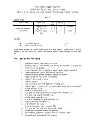
<strong>CAR</strong>-<strong>14</strong>the facility is provided. When applying this <strong>CAR</strong>-<strong>14</strong>, the aeroplanes which the aerodromeis intended toserve are first identified and then the two elements <strong>of</strong> the code.1.7.1 An aerodrome reference code — code number and letter — which is selected foraerodrome planning purposes shall be determined in accordance with the characteristics<strong>of</strong> the aeroplane for which an aerodrome facility is intended.1.7.2 The aerodrome reference code numbers and letters shall have the meanings assignedto them in Table 1-1.1.7.3 The code number for element 1 shall be determined from Table 1-1, column 1,selecting the code number corresponding to the highest value <strong>of</strong> the aeroplane referencefield lengths <strong>of</strong> the aeroplanes for which the runway is intended.Note.— The determination <strong>of</strong> the aeroplane reference field length is solely for theselection <strong>of</strong> a code number and is not intended to influence the actual runway lengthprovided.1.7.4 The code letter for element 2 shall be determined from Table 1-1, column 3, byselecting the code letter which corresponds to the greatest wing span, or the greatest outermain gear wheel span, whichever gives the more demanding code letter <strong>of</strong> the aeroplanesfor which the facility isintended.Note.— Guidance to assist the appropriate authority in determining the aerodromereference code is given in the Aerodrome Design Manual (Doc 9157), <strong>Part</strong>s 1 and 2.Table 1-1. Aerodrome reference codeNote: Annexes, Manuals/Documents etc. are refered to ICAO Annexes, Manuals/DocumentsPage 11 <strong>Civil</strong> <strong>Aviation</strong> <strong>Authority</strong> <strong>of</strong> <strong>Nepal</strong> September 2012
<strong>CAR</strong>-<strong>14</strong>CHAPTER- 2AERODROME DATA2.1 Aeronautical data2.1.1 Determination and reporting <strong>of</strong> aerodrome related aeronautical data shall be inaccordance with the accuracy and integrity requirements set forth in Tables 1 to 5 containedin Appendix 5 while taking into account the established quality system procedures. Accuracyrequirements for aeronautical data are based upon a 95 per cent confidence level and in thatrespect, three types <strong>of</strong> positional data shall be identified:a. surveyed points (e.g. runway threshold)b. calculated points (mathematical calculations from the known surveyed points <strong>of</strong> points inspace, fixes) andc. declared points (e.g. flight information region boundary points).Note.— Specifications governing the quality system are given in ICAO Annex 15, Chapter 3.2.1.2 Aerodrome Operators shall ensure that integrity <strong>of</strong> aeronautical data is maintainedthroughout the data process from survey/origin to the next intended user. Aeronautical dataintegrity requirements shall be based upon the potential risk resulting from the corruption <strong>of</strong>data and upon the use to which the data item is put. Consequently, the followingclassification and data integrity level shall apply:a) critical data, integrity level 1X10 -8 : there is a high probability when using corrupted criticaldata that the continued safe flight and landing <strong>of</strong> an aircraft would be severely at risk with thepotential for catastrophe;b) essential data, integrity level 1X10 -5 : there is a low probability when using corruptedessential data that the continued safe flight and landing <strong>of</strong> an aircraft would be severely atrisk with the potential for catastrophe; andc) routine data, integrity level 1X10 -3 : there is a very low probability when using corruptedroutine data that the continued safe flight and landing <strong>of</strong> an aircraft would be severely at riskwith the potential for catastrophe.2.1.3 Protection <strong>of</strong> electronic aeronautical data while stored or in transit shall be totallymonitored by the cyclic redundancy check (CRC). To achieve protection <strong>of</strong> the integrity level<strong>of</strong> critical and essential aeronautical data as classified in 2.1.2, a 32 or 24 bit CRC algorithmshall apply respectively.2.1.4 Recommendation.- To achieve protection <strong>of</strong> the integrity level <strong>of</strong> routine aeronauticaldata as classified in 2.1.2, a 16 bit CRC algorithm should apply.Note.— Guidance material on the aeronautical data quality requirements (accuracy,resolution, integrity, protection and traceability) is contained in the World Geodetic System— 1984 (WGS-84) Manual (Doc 9674). Supporting material in respect <strong>of</strong> the provisions <strong>of</strong>Appendix 5 related to accuracy and integrity <strong>of</strong> aeronautical data, is contained in RTCADocument DO-201A and European Organization for <strong>Civil</strong> <strong>Aviation</strong> Equipment (EUROCAE)Document ED-77, entitled Industry Requirements for Aeronautical Information.Page 12 <strong>Civil</strong> <strong>Aviation</strong> <strong>Authority</strong> <strong>of</strong> <strong>Nepal</strong> September 2012
<strong>CAR</strong>-<strong>14</strong>2.1.5 Geographical coordinates indicating latitude and longitude shall be determined andreported to the aeronautical information services authority in terms <strong>of</strong> the World GeodeticSystem —1984 (WGS-84) geodetic reference datum, identifying those geographicalcoordinates which have been transformed into WGS-84 coordinates by mathematical meansand whose accuracy <strong>of</strong> original field work does not meet the requirements in Appendix 5,Table A5-1.2.1.6 The order <strong>of</strong> accuracy <strong>of</strong> the field work shall be such that the resulting operationalnavigation data for the phases <strong>of</strong> flight will be within the maximum deviations, with respectto an appropriate reference frame, as indicated in tables contained in Appendix 5.2.1.7 In addition to the elevation (referenced to mean sea level) <strong>of</strong> the specific surveyedground positions at aerodromes, geoid undulation (referenced to the WGS-84 ellipsoid) forthose positions as indicated in Appendix 5, shall be determined and reported to theaeronautical information services authority.Note 1.— An appropriate reference frame is that which enables WGS-84 to be realized ona given aerodrome and with respect to which all coordinate data are related.Note 2.— Specifications governing the publication <strong>of</strong> WGS-84 coordinates are given inAnnex 4, Chapter 2 and Annex 15, Chapter 3.2.2 Aerodrome reference point2.2.1 An aerodrome reference point shall be established for an aerodrome.2.2.2 The aerodrome reference point shall be located near the initial or planned geometriccentre <strong>of</strong> the aerodrome and shall normally remain where first established.2.2.3 The position <strong>of</strong> the aerodrome reference point shall be measured and reported to theaeronautical information services authority in degrees, minutes and seconds.2.3 Aerodrome and runway elevations2.3.1 The aerodrome elevation and geoid undulation at the aerodrome elevation position shallbe measured to the accuracy <strong>of</strong> one-half metre or foot and reported to the aeronauticalinformation services authority.2.3.2 For an aerodrome used by international civil aviation for non-precision approaches, theelevation and geoid undulation <strong>of</strong> each threshold, the elevation <strong>of</strong> the runway end and anysignificant high and low intermediate points along the runway shall be measured to theaccuracy <strong>of</strong> one-half metre or foot and reported to the aeronautical information servicesauthority.2.3.3 For precision approach runway, the elevation and geoid undulation <strong>of</strong> the threshold, theelevation <strong>of</strong> the runway end and the highest elevation <strong>of</strong> the touchdown zone shall bemeasured to the accuracy <strong>of</strong> one-quarter metre or foot and reported to the aeronauticalinformation services authority.Note.— Geoid undulation must be measured in accordance with the appropriate system <strong>of</strong>coordinates.Page 13 <strong>Civil</strong> <strong>Aviation</strong> <strong>Authority</strong> <strong>of</strong> <strong>Nepal</strong> September 2012
<strong>CAR</strong>-<strong>14</strong>2.4 Aerodrome reference temperature2.4.1 An aerodrome reference temperature shall be determined for an aerodrome in degreesCelsius.2.4.2 The aerodrome reference temperature shall be the monthly mean <strong>of</strong> the daily maximumtemperatures for the hottest month <strong>of</strong> the year (the hottest month being that which has thehighest monthly mean temperature). This temperature should be averaged over a period <strong>of</strong>years.2.5 Aerodrome dimensions and related information2.5.1 The following data shall be measured or described, as appropriate, for each facilityprovided on an aerodrome:a) runway — true bearing to one-hundredth <strong>of</strong> a degree, designation number, length, width,displaced threshold location to the nearest metre or foot, slope, surface type, type <strong>of</strong> runwayand, for a precision approach runway category I, the existence <strong>of</strong> an obstacle free zone whenprovided;b) strip, runway end safety area and stopway - length, width to the nearest metre or foot,surface type;c) taxiway — designation, width, surface type;d) apron — surface type, aircraft stands;e) the boundaries <strong>of</strong> the air traffic control service;f) clearway — length to the nearest metre or foot, ground pr<strong>of</strong>ile;g) visual aids for approach procedures, marking and lighting <strong>of</strong> runways, taxiways andaprons, other visual guidance and control aids on taxiways and aprons, including taxi-holdingpositions and stopbars, and location and type <strong>of</strong> visual docking guidance systems;h) location and radio frequency <strong>of</strong> any VOR aerodrome check-point;i) location and designation <strong>of</strong> standard taxi-routes; andj) distances to the nearest metre or foot <strong>of</strong> localizer and glide path elements comprising aninstrument landing system (ILS) or azimuth and elevation antenna <strong>of</strong> microwave landingsystem (MLS) in relation to the associated runway extremities.2.5.2 The geographical coordinates <strong>of</strong> each threshold shall be measured and reported to theaeronautical information services authority in degrees, minutes, seconds and hundredths <strong>of</strong>seconds.2.5.3 The geographical coordinates <strong>of</strong> appropriate taxiway centre line points shall bemeasured and reported to the aeronautical information services authority in degrees, minutes,seconds and hundredths <strong>of</strong> seconds.2.5.4 The geographical coordinates <strong>of</strong> each aircraft stand shall be measured and reported tothe aeronautical information services authority in degrees, minutes, seconds and hundredths<strong>of</strong> seconds.Page <strong>14</strong> <strong>Civil</strong> <strong>Aviation</strong> <strong>Authority</strong> <strong>of</strong> <strong>Nepal</strong> September 2012
<strong>CAR</strong>-<strong>14</strong>2.5.5 The geographical coordinates <strong>of</strong> obstacles in Area 2 (the part within the aerodromeboundary) and in Area 3 shall be measured and reported to the aeronautical informationservices authority in degrees, minutes, seconds and tenths <strong>of</strong> seconds. In addition, the topelevation, type, marking and lighting (if any) <strong>of</strong> obstacles shall be reported to the aeronauticalinformation services authority.Note 1.— See Annex 15, Appendix 8, for graphical illustrations <strong>of</strong> obstacle data collectionsurfaces and criteria used to identify obstacles in Areas 2 and 3.Note 2.—Appendix 5 provides requirements for obstacle data determination in Areas 2 and 3.Note 3.—Implementation <strong>of</strong> Annex 15, 10.6.1.2, concerning the availability, <strong>of</strong> obstacle dataaccording to Area 2 and Area 3 specifications would be facilitated by appropriate advanceplanning for the collection and processing <strong>of</strong> such data.2.6 Strength <strong>of</strong> pavements2.6.1 The bearing strength <strong>of</strong> a pavement shall be determined.2.6.2 The bearing strength <strong>of</strong> a pavement intended for aircraft <strong>of</strong> apron (ramp) mass greaterthan 5 700 kg shall be made available using the aircraft classification number — pavementclassification number (ACN-PCN) method by reporting all <strong>of</strong> the following information:a) the pavement classification number (PCN);b) pavement type for ACN-PCN determination;c) subgrade strength category;d) maximum allowable tire pressure category or maximum allowable tire pressure value; ande) evaluation method.Note.— If necessary, PCNs may be published to an accuracy <strong>of</strong> one-tenth <strong>of</strong> a whole number.2.6.3 The pavement classification number (PCN) reported shall indicate that an aircraft withan aircraft classification number (ACN) equal to or less than the reported PCN can operate onthe pavement subject to any limitation on the tire pressure, or aircraft all-up mass forspecified aircraft type(s).Note.— Different PCNs may be reported if the strength <strong>of</strong> the pavement is subject tosignificant seasonal variation.2.6.4 The ACN <strong>of</strong> an aircraft shall be determined in accordance with the standard proceduresassociated with the ACN-PCN method.Note.— The standard procedures for determining the ACN <strong>of</strong> an aircraft are given in theICAO Aerodrome Design Manual, <strong>Part</strong> 3. For convenience several aircraft types currently inuse have been evaluated on rigid and flexible pavements founded on the four subgradecategories in 2.6.6 b) below and the results tabulated in that manual.2.6.5 For the purposes <strong>of</strong> determining the ACN, the behaviour <strong>of</strong> a pavement shall beclassified as equivalent to a rigid or flexible construction.Page 15 <strong>Civil</strong> <strong>Aviation</strong> <strong>Authority</strong> <strong>of</strong> <strong>Nepal</strong> September 2012
<strong>CAR</strong>-<strong>14</strong>2.6.6 Information on pavement type for ACN-PCN determination, subgrade strengthcategory, maximum allowable tire pressure category and evaluation method shall be reportedusing the following codes:a) Pavement type for ACN-PCN determination: CodeRigid pavementFlexible pavementRFNote.— If the actual construction is composite or nonstandard, include a note to that effect(see example 2 below).b) Subgrade strength category: CodeHigh strength: characterized by K =150 MN/m3 and representingall K values above 120 MN/m3 for rigid pavements, and by CBR = 15and representing all CBR values above 13 for flexible pavements.Medium strength: characterized by K =80 MN/m3 and representinga range in K <strong>of</strong> 60 to 120 MN/m3 for rigid pavements, and by CBR = 10and representing a range in CBR <strong>of</strong> 8 to 13 for flexible pavements.Low strength: characterized by K = 40 MN/m3 and representing arange in K <strong>of</strong> 25 to 60 MN/m3 for rigid pavements, and by CBR = 6and representing a range in CBR <strong>of</strong> 4 to 8 for flexible pavements.Ultra low strength: characterized by K =20 MN/m3 and representingall K values below 25 MN/m3 for rigid pavements, and by CBR = 3and representing all CBR values below 4 for flexible pavements.ABCDc) Maximum allowable tire pressure category: CodeHigh: no pressure limitMedium: pressure limited to 1.50 MPaLow: pressure limited to 1.00 MPaVery low: pressure limited to 0.50 MPaWXYZd) Evaluation method: CodeTechnical evaluation: representing a specific study <strong>of</strong> the pavementCharacteristics and application <strong>of</strong> pavement behaviour technology.Using aircraft experience: representing a knowledge <strong>of</strong> the specifictype and mass <strong>of</strong> aircraft satisfactorily being supported under regular use.TUNote.— The following examples illustrate how pavement strength data are reported under theACN-PCN method.Page 16 <strong>Civil</strong> <strong>Aviation</strong> <strong>Authority</strong> <strong>of</strong> <strong>Nepal</strong> September 2012
<strong>CAR</strong>-<strong>14</strong>Example 1.— If the bearing strength <strong>of</strong> a rigid pavement, resting on a medium strengthsubgrade, has been assessed by technical evaluation to be PCN 80 and there is no tirepressure limitation, then the reported information would be:PCN 80 / R / B / W / TExample 2.— If the bearing strength <strong>of</strong> a composite pavement, behaving like a flexiblepavement and resting on a high strength subgrade, has been assessed by using aircraftexperience to be PCN 50 and the maximum tire pressure allowable is 1.00 MPa, then thereported information would be:PCN 50 / F / A / Y / UNote.— Composite construction.Example 3.— If the bearing strength <strong>of</strong> a flexible pavement, resting on a medium strengthsubgrade, has been assessed by technical evaluation to be PCN 40 and the maximumallowable tire pressure is 0.80 MPa, then the reported information would be:PCN 40 / F / B / 0.80 MPa /TExample 4.— If a pavement is subject to a B747-400 all-up mass limitation <strong>of</strong> 390 000 kg,then the reported information would include the following note.Note.— The reported PCN is subject to a B747-400 all-up mass limitation <strong>of</strong> 390 000 kg.2.6.7 Recommendation.- Criteria should be established to regulate the use <strong>of</strong> a pavement byan aircraft with an ACN higher than the PCN reported for that pavement in accordance with2.6.2 and 2.6.3.Note.— Attachment A, Section 19 details a simple method for regulating overload operationswhile the ICAO Aerodrome Design Manual, <strong>Part</strong> 3 includes the descriptions <strong>of</strong> more detailedprocedures for evaluation <strong>of</strong> pavements and their suitability for restricted overloadoperations.2.6.8 The bearing strength <strong>of</strong> a pavement intended for aircraft <strong>of</strong> apron (ramp) mass equal toor less than 5 700 kg shall be made available by reporting the following information:a) maximum allowable aircraft mass; andb) maximum allowable tire pressure.Example: 4 000 kg/0.50 MPa.2.7 Pre-flight altimeter check location2.7.1 One or more pre-flight altimeter check locations shall be established for an aerodrome.2.7.2 A pre-flight check location shall be located on an apron.2.7.3 The elevation <strong>of</strong> a pre-flight altimeter check location shall be given as the averageelevation, rounded to the nearest metre or foot, <strong>of</strong> the area on which it is located. Theelevation <strong>of</strong> any portion <strong>of</strong> a pre-flight altimeter check location shall be within 3 m (10 ft) <strong>of</strong>the average elevation for that location.Page 17 <strong>Civil</strong> <strong>Aviation</strong> <strong>Authority</strong> <strong>of</strong> <strong>Nepal</strong> September 2012
<strong>CAR</strong>-<strong>14</strong>2.8 Declared distancesThe following distances shall be calculated to the nearest metre or foot for a runway intendedfor use by international commercial air transport:a) take-<strong>of</strong>f run available;b) take-<strong>of</strong>f distance available;c) accelerate-stop distance available; andd) landing distance available.Note.— Guidance on calculation <strong>of</strong> declared distances is given in Attachment A, Section 3.2.9 Condition <strong>of</strong> the movement area and related facilities2.9.1 Information on the condition <strong>of</strong> the movement area and the operational status <strong>of</strong> relatedfacilities shall be provided to the appropriate aeronautical information service units, andsimilar information <strong>of</strong> operational significance to the air traffic services units, to enable thoseunits to provide the necessary information to arriving and departing aircraft. The informationshall be kept up to date and changes in conditions reported without delay.2.9.2 The condition <strong>of</strong> the movement area and the operational status <strong>of</strong> related facilities shallbe monitored and reports on matters <strong>of</strong> operational significance or affecting aircraftperformance given, particularly in respect <strong>of</strong> the following:a) construction or maintenance work;b) rough or broken surfaces on a runway, a taxiway or an apron;c) snow, slush or ice on a runway, a taxiway or an apron; d) water on a runway, a taxiwayor an apron;e) snow banks or drifts adjacent to a runway, a taxiway or an apron;f) anti-icing or de-icing liquid chemicals on a runway or a taxiway;g) other temporary hazards, including parked aircraft;h) failure or irregular operation <strong>of</strong> part or all <strong>of</strong> the aerodrome visual aids; andi) failure <strong>of</strong> the normal or secondary power supply.2.9.3 Inspections <strong>of</strong> the movement area shall be carried out each day at least once where thecode number is 1or 2 and at least twice where the code number is 3 or 4 in order to facilitatecompliance with 2.9.1 and 2.9.2.Note.— Guidance on carrying out daily inspections <strong>of</strong> the movement area is given in theICAO Airport Services Manual, <strong>Part</strong> 8 and in the ICAO Manual <strong>of</strong> Surface MovementGuidance and Control Systems (SMGCS).Page 18 <strong>Civil</strong> <strong>Aviation</strong> <strong>Authority</strong> <strong>of</strong> <strong>Nepal</strong> September 2012
<strong>CAR</strong>-<strong>14</strong>Water on a runway2.9.4 Whenever water is present on a runway, a description <strong>of</strong> the runway surface conditionson the centre half <strong>of</strong> the width <strong>of</strong> the runway, including the possible assessment <strong>of</strong> waterdepth, where applicable, shall be made available using the following terms:DAMP — the surface shows a change <strong>of</strong> colour due to moisture.WET — the surface is soaked but there is no standing water.WATER PATCHES — significant patches <strong>of</strong> standing water are visible.FLOODED — extensive standing water is visible.2.9.5 Information that a runway or portion there<strong>of</strong> may be slippery when wet shall be madeavailable.2.9.6 A runway or portion there<strong>of</strong> shall be determined as being slippery when wet when themeasurements specified in 10.2.3 show that the runway surface friction characteristics asmeasured by a continuous friction measuring device are below the minimum friction levelspecified in the Attachment A, Table A – 1.Note.— Guidance on determining and expressing the minimum friction level is provided inAttachment A, Section 7.2.9.7 The minimum friction levels specified in the Attachment A, Table A – 1 for thedifferent types <strong>of</strong> friction measuring devices shall be taken for reporting slippery runwayconditions.2.9.8 Recommendation.- When it is suspected that a runway may become slippery underunusual conditions, then additional measurements should be made when such conditionsoccur, and information on the runway surface friction characteristics made available whenthese additional measurements show that the runway or a portion there<strong>of</strong> has becomeslippery.Snow, slush or ice on a runwayNote 1.— The intent <strong>of</strong> these specifications is to satisfy the SNOWTAM and NOTAMpromulgation requirements contained in Annex 15.Note 2.— Runway surface condition sensors may be used to detect and continuouslydisplay current or predicted information on surface conditions such as the presence <strong>of</strong>moisture, or imminent formation <strong>of</strong> ice on pavements.2.9.9 Recommendation.— Whenever a runway is affected by snow, slush or ice, and it hasnot been possible to clear the precipitant fully, the condition <strong>of</strong> the runway should beassessed, and the friction coefficient measured.Note.— Guidance on determining and expressing the friction characteristics <strong>of</strong> snow- andice-covered paved surfaces is provided in Attachment A, Section 6.2.9.10 Recommendation.— The readings <strong>of</strong> the friction measuring device on snow-,slush-, or ice-covered surfaces should adequately correlate with the readings <strong>of</strong> one othersuch device.Note.— The principal aim is to measure surface friction in a manner that is relevant to thePage 19 <strong>Civil</strong> <strong>Aviation</strong> <strong>Authority</strong> <strong>of</strong> <strong>Nepal</strong> September 2012
<strong>CAR</strong>-<strong>14</strong>friction experienced by an aircraft tire, thereby providing correlation between the frictionmeasuring device and aircraft braking performance.2.9.11 Recommendation.— Whenever dry snow, wet snow or slush is present on a runway,an assessment <strong>of</strong> the mean depth over each third <strong>of</strong> the runway should be made to anaccuracy <strong>of</strong> approximately 2 cm for dry snow, 1 cm for wet snow and 0.3 cm for slush.2.10 Disabled aircraft removalNote.— See 9.3 for information on disabled aircraft removal services.2.10.1 The telephone/telex number(s) <strong>of</strong> the <strong>of</strong>fice <strong>of</strong> the aerodrome coordinator <strong>of</strong> operationsfor the removal <strong>of</strong> an aircraft disabled on or adjacent to the movement area shall be madeavailable, on request, to aircraft operators.2.10.2 Recommendation.- Information concerning the capability to remove an aircraftdisabled on or adjacent to the movement area should be made available.Note.— The capability to remove a disabled aircraft may be expressed in terms <strong>of</strong> the largesttype <strong>of</strong> aircraft which the aerodrome is equipped to remove.2.11 Rescue and fire fightingNote.— See 9.2 for information on rescue and fire fighting services.2.11.1 Information concerning the level <strong>of</strong> protection provided at an aerodrome for aircraftrescue and fire fighting purposes shall be made available.2.11.2 Recommendation.- The level <strong>of</strong> protection normally available at an aerodromeshould be expressed in terms <strong>of</strong> the category <strong>of</strong> the rescue and fire fighting services asdescribed in 9.2 and in accordance with the types and amounts <strong>of</strong> extinguishing agentsnormally available at the aerodrome.2.11.3 Significant changes in the level <strong>of</strong> protection normally available at an aerodrome forrescue and fire fighting shall be notified to the appropriate air traffic services units andaeronautical information units to enable those units to provide the necessary information toarriving and departing aircraft. When such a change has been corrected, the above units shallbe advised accordingly.Note.— A significant change in the level <strong>of</strong> protection is considered to be a change in thecategory <strong>of</strong> the rescue and fire fighting service from the category normally available at theaerodrome, resulting from a change in availability <strong>of</strong> extinguishing agents, equipment todeliver the agents or personnel to operate the equipment, etc.2.11.4 Recommendation.- A significant change should be expressed in terms <strong>of</strong> the newcategory <strong>of</strong> the rescue and fire fighting service available at the aerodrome.2.12 Visual approach slope indicator systemsThe following information concerning a visual approach slope indicator system installationshall be made available:a) associated runway designation number;Page 20 <strong>Civil</strong> <strong>Aviation</strong> <strong>Authority</strong> <strong>of</strong> <strong>Nepal</strong> September 2012
<strong>CAR</strong>-<strong>14</strong>b) type <strong>of</strong> system according to 5.3.5.2. for an AT-VASIS, PAPI or APAPI installation, theside <strong>of</strong> the runway on which the lights are installed, i.e. left or right, shall be given;c) where the axis <strong>of</strong> the system is not parallel to the runway centre line, the angle <strong>of</strong>displacement and the direction <strong>of</strong> displacement, i.e. left or right shall be indicated;d) nominal approach slope angle(s). For a T-VASIS or an AT-VASIS this shall be angle θaccording to the formula in Figure 5-17 and for a PAPI and an APAPI this shall be angle(B + C) /2 and (A + B) /2, respectively as in Figure 5-19; ande) minimum eye height(s) over the threshold <strong>of</strong> the on-slope signal(s). For a T-VASIS or anAT-VASIS this shall be the lowest height at which only the wing bar(s) are visible; however,the additional heights at which the wing bar(s) plus one, two or three fly down light unitscome into view may also be reported if such information would be <strong>of</strong> benefit to aircraft usingthe approach. For a PAPI this shall be the setting angle <strong>of</strong> the third unit from the runwayminus 2′, i.e. angle B minus 2′, and for an APAPI this shall be the setting angle <strong>of</strong> the unitfarther from the runway minus 2′, i.e. angle A minus 2′.2.13 Coordination between aeronautical information services and aerodromeauthorities2.13.1 To ensure that aeronautical information services units obtain information to enablethem to provide up-to-date pre-flight information and to meet the need for in-flightinformation, arrangements shall be made between aeronautical information services andaerodrome authorities responsible for aerodrome services to report to the responsibleaeronautical information services unit, with a minimum <strong>of</strong> delay:a) information on aerodrome conditions (ref. 2.9, 2.10, 2.11 and 2.12);b) the operational status <strong>of</strong> associated facilities, services and navigation aids within their area<strong>of</strong> responsibility;c) any other information considered to be <strong>of</strong> operational significance.2.13.2 Before introducing changes to the air navigation system, due account shall be taken bythe services responsible for such changes <strong>of</strong> the time needed by the aeronautical informationservice for the preparation, production and issue <strong>of</strong> relevant material for promulgation. Toensure timely provision <strong>of</strong> the information to the aeronautical information service, closecoordination between those services concerned is therefore required.2.13.3 Of a particular importance are changes to aeronautical information that affect chartsand/or computer based navigation systems which qualify to be notified by the aeronauticalinformation regulation and control (AIRAC) system. The predetermined, internationallyagreed AIRAC effective dates in addition to <strong>14</strong> days postage time shall be observed by theresponsible aerodrome services when submitting the raw information/data to aeronauticalinformation services.2.13.4 The aerodrome services responsible for the provision <strong>of</strong> raw aeronauticalinformation/data to the aeronautical information services shall do that while taking intoaccount accuracy and integrity requirements for aeronautical data as specified in Appendix 5to this document.Note 1.— Specifications for the issue <strong>of</strong> a NOTAM are contained in Annex 15, Chapter 5and Appendices 6 and 2, respectively.Note 2.— AIRAC information is distributed by the AIS at least 42 days in advance <strong>of</strong> thePage 21 <strong>Civil</strong> <strong>Aviation</strong> <strong>Authority</strong> <strong>of</strong> <strong>Nepal</strong> September 2012
<strong>CAR</strong>-<strong>14</strong>AIRAC effective dates with the objective <strong>of</strong> reaching recipients at least 28 days in advance<strong>of</strong> the effective date.Note 3.— The schedule <strong>of</strong> the predetermined internationally agreed AIRAC commoneffective dates at intervals <strong>of</strong> 28 days, including 6 November 1997 and guidance for theAIRAC use are contained in the ICAO Aeronautical Information Services Manual (Doc8126, Chapter 2).Page 22 <strong>Civil</strong> <strong>Aviation</strong> <strong>Authority</strong> <strong>of</strong> <strong>Nepal</strong> September 2012
<strong>CAR</strong>-<strong>14</strong>CHAPTER -3PHYSICAL CHARACTERISTICS3.1 RunwaysNumber and orientation <strong>of</strong> runwaysMany factors affect the determination <strong>of</strong> the orientation, siting and number <strong>of</strong> runways. Oneimportant factor is the usability factor, as determined by the wind distribution, which isspecified hereunder. Another important factor is the alignment <strong>of</strong> the runway to facilitate theprovision <strong>of</strong> approaches conforming to the approach surface specifications <strong>of</strong> Chapter 4. InAttachment A, Section 1, information is given concerning these and other factors.When a new instrument runway is being located, particular attention needs to be given toareas over which aeroplanes will be required to fly when following instrument approach andmissed approach procedures, so as to ensure that obstacles in these areas or other factorswill not restrict the operation <strong>of</strong> the aeroplanes for which the runway is intended.3.1.1 Recommendation.- The number and orientation <strong>of</strong> runways at an aerodrome should besuch that the usability factor <strong>of</strong> the aerodrome is not less than 95 per cent for the aeroplanesthat the aerodrome is intended to serve.3.1.2 Recommendation.- The siting and orientation <strong>of</strong> runways at an aerodrome should,where possible, be such that the arrival and departure tracks minimize interference withareas approved for residential use and other noise sensitive areas close to the aerodrome inorder to avoid future noise problems.Note.- Guidance on how to address noise problems is provided in the ICAO AirportPlanning Manual, <strong>Part</strong> 2, and in Guidance on the Balanced Approach to Aircraft NoiseManagement (Doc 9829).3.1.3 Choice <strong>of</strong> maximum permissible cross-wind componentsRecommendation.- In the application <strong>of</strong> 3.1.1 it should be assumed that landing or take-<strong>of</strong>f<strong>of</strong> aeroplanes is, in normal circumstances, precluded when the cross-wind componentexceeds:- 37 km/h (20 kt) in the case <strong>of</strong> aeroplanes whose reference field length is 1 500 m or over,except that when poor runway braking action owing to an insufficient longitudinal coefficient<strong>of</strong> friction is experienced with some frequency, a cross-wind component not exceeding 24km/h (13 kt) should be assumed;- 24 km/h (13 kt) in the case <strong>of</strong> aeroplanes whose reference field length is 1 200 m or up tobut not including 1 500 m; and- 19 km/h (10 kt) in the case <strong>of</strong> aeroplanes whose reference field length is less than 1 200 m.Page 23 <strong>Civil</strong> <strong>Aviation</strong> <strong>Authority</strong> <strong>of</strong> <strong>Nepal</strong> September 2012
<strong>CAR</strong>-<strong>14</strong>Note.— In Attachment A, Section 1, guidance is given on factors affecting the calculation <strong>of</strong>the estimate <strong>of</strong> the usability factor and allowances which may have to be made to takeaccount <strong>of</strong> the effect <strong>of</strong> unusual circumstances.3.1.4 Data to be usedRecommendation.- The selection <strong>of</strong> data to be used for the calculation <strong>of</strong> the usability factorshould be based on reliable wind distribution statistics that extend over as long a period aspossible, preferably <strong>of</strong> not less than five years. The observations used should be made at leasteight times daily and spaced at equal intervals <strong>of</strong> time.Note.— These winds are mean winds. Reference to the need for some allowance for gustyconditions is made in Attachment A, Section 1.Location <strong>of</strong> threshold3.1.5 Recommendation.- A threshold should normally be located at the extremity <strong>of</strong> arunway unless operational considerations justify the choice <strong>of</strong> another location.Note.— Guidance on the siting <strong>of</strong> the threshold is given in Attachment A, Section 10.3.1.6 Recommendation.- When it is necessary to displace a threshold, either permanently ortemporarily, from its normal location, account should be taken <strong>of</strong> the various factors whichmay have a bearing on the location <strong>of</strong> the threshold. Where this displacement is due to anunserviceable runway condition, a cleared and graded area <strong>of</strong> at least 60 m in length shouldbe available between the unserviceable area and the displaced threshold. Additional distanceshould also be provided to meet the requirements <strong>of</strong> the runway end safety area asappropriate.Note.— Guidance on factors which may be considered in the determination <strong>of</strong> the location <strong>of</strong>a displaced threshold is given in Attachment A, Section 10.Actual length <strong>of</strong> runways3.1.7 Primary runwayRecommendation.- Except as provided in 3.1.9 the actual runway length to be provided fora primary runway should be adequate to meet the operational requirements <strong>of</strong> the aeroplanesfor which the runway is intended and shall be not less than the longest length determined byapplying the corrections for local conditions to the operations and performancecharacteristics <strong>of</strong> the relevant aeroplanes.Note 1.— This specification does not necessarily mean providing for operations by thecritical aeroplane at its maximum mass.Note 2.— Both take-<strong>of</strong>f and landing requirements need to be considered when determiningthe length <strong>of</strong> runway to be provided and the need for operations to be conducted in bothdirections <strong>of</strong> the runway.Note 3.— Local conditions that may need to be considered include elevation, temperature,runway slope, humidity and the runway surface characteristics.Page 24 <strong>Civil</strong> <strong>Aviation</strong> <strong>Authority</strong> <strong>of</strong> <strong>Nepal</strong> September 2012
<strong>CAR</strong>-<strong>14</strong>Note 4.— When performance data on aeroplanes for which the runway is intended are notknown, guidance on the determination <strong>of</strong> the actual length <strong>of</strong> a primry runway by application<strong>of</strong> general correction factors is given in the ICAO Aerodrome Design Manual, <strong>Part</strong> 1.3.1.8 Secondary runwayRecommendation.- The length <strong>of</strong> a secondary runway should be determined similarly toprimary runways except that it needs only to be adequate for those aeroplanes which requireto use that secondary runway in addition to the other runway or runways in order to obtain ausability factor <strong>of</strong> at least 95 per cent.3.1.9 Runways with stopways or clearwaysRecommendation.- Where a runway is associated with a stopway or clearway, an actualrunway length less than that resulting from application <strong>of</strong> 3.1.7 or 3.1.8, as appropriate, maybe considered satisfactory, but in such a case any combination <strong>of</strong> runway, stopway andclearway provided should permit compliance with the operational requirements for take-<strong>of</strong>fand landing <strong>of</strong> the aeroplanes the runway is intended to serve.Note.— Guidance on use <strong>of</strong> stopways and clearways is given in Attachment A, Section 2.Width <strong>of</strong> runways3.1.10 The width <strong>of</strong> a runway shall not be less than the appropriate dimension specified in thefollowing tabulation:a. The width <strong>of</strong> a precision approach runway should be not less than 30 m where the codenumber is 1 or 2.Note 1.— The combinations <strong>of</strong> code numbers and letters for which widths are specified havebeen developed for typical aeroplane characteristics.Note 2.— Factors affecting runway width are given in the ICAO Aerodrome Design Manual,<strong>Part</strong> 1.Minimum distance between parallel runways3.1.11 Where parallel non-instrument runways are intended for simultaneous use, theminimum distance between their centre lines shall be:- 210 m where the higher code number is 3 or 4;- 150 m where the higher code number is 2; and- 120 m where the higher code number is 1Page 25 <strong>Civil</strong> <strong>Aviation</strong> <strong>Authority</strong> <strong>of</strong> <strong>Nepal</strong> September 2012
<strong>CAR</strong>-<strong>14</strong>Note.— Procedures for wake turbulence categorization <strong>of</strong> aircraft and wake turbulenceseparation minima are contained in the ICAO Procedures for Air Navigation Services — AirTraffic Management (PANS-ATM), Doc 4444, Chapter 4, 4.9 and Chapter 5, 5.8,respectively.3.1.12 Where parallel instrument runways are intended for simultaneous use subject toconditions specified in the ICAO PANS-ATM (Doc 4444) and the ICAO PANS-OPS (Doc8168), <strong>Part</strong> 1, the minimum distance between their centre lines shall be:- 1 035 m for independent parallel approaches;- 915 m for dependent parallel approaches;- 760 m for independent parallel departures;- 760 m for segregated parallel operations;except that:a) for segregated parallel operations the specified minimum distance:1) may be decreased by 30 m for each 150 m that the arrival runway is staggered towardthe arriving aircraft, to a minimum <strong>of</strong> 300 m; and2) should be increased by 30 m for each 150 m that the arrival runway is staggered awayfrom the arriving aircraft;b) for independent parallel approaches, combinations <strong>of</strong> minimum distances and associatedconditions other than those specified in the ICAO PANS-ATM (Doc 4444) may beapplied when it is determined that such combinations would not adversely affect thesafety <strong>of</strong> aircraft operations.Note.— Procedures and facilities requirements for simultaneous operations on parallel ornear-parallel instrument runways are contained in the ICAO PANS-ATM (Doc 4444),Chapter 6 and the ICAO PANS-OPS (Doc 8168), <strong>Part</strong> 1, <strong>Part</strong> VII and <strong>Part</strong> 1I, <strong>Part</strong>s II andIII and relevant guidance is contained in the ICAO Manual <strong>of</strong> Simultaneous Operations onParallel or Near-Parallel Instrument Runways (Doc 9643).Slopes on runways3.1.13 Longitudinal slopesRecommendation.- The slope computed by dividing the difference between the maximumand minimum elevation along the runway centre line by the runway length should not exceed:— 1 per cent where the code number is 3 or 4; and— 2 per cent where the code number is 1 or 2.3.1.<strong>14</strong> Recommendation.- Along no portion <strong>of</strong> a runway should the longitudinal slopeexceed:- 1.25 per cent where the code number is 4, except that for the first and last quarter <strong>of</strong> thelength <strong>of</strong> the runway the longitudinal slope should not exceed 0.8 per cent;- 1.5 per cent where the code number is 3, except that for the first and last quarter <strong>of</strong> thelength <strong>of</strong> a precision approach runway category II or III the longitudinal slope shouldnot exceed 0.8 per cent; and- 2 per cent where the code number is 1 or 2.Page 26 <strong>Civil</strong> <strong>Aviation</strong> <strong>Authority</strong> <strong>of</strong> <strong>Nepal</strong> September 2012
3.1.15 Longitudinal slope changes<strong>CAR</strong>-<strong>14</strong>Recommendation.- Where slope changes cannot be avoided, a slope change between twoconsecutive slopes should not exceed:- 1.5 per cent where the code number is 3 or 4; and- 2 per cent where the code number is 1 or 2.Note.— Guidance on slope changes before a runway is given in Attachment A, Section 4.3.1.16 Recommendation.- The transition from one slope to another should be accomplishedby a curved surface with a rate <strong>of</strong> change not exceeding:- 0.1 per cent per 30 m (minimum radius <strong>of</strong> curvature <strong>of</strong> 30 000 m) where the codenumber is 4;- 0.2 per cent per 30 m (minimum radius <strong>of</strong> curvature <strong>of</strong> 15 000 m) where the codenumber is 3; and- 0.4 per cent per 30 m (minimum radius <strong>of</strong> curvature <strong>of</strong> 7 500 m) where the codenumber is 1 or 2.3.1.17 Sight distanceRecommendation.- Where slope changes cannot be avoided, they should be such that therewill be an unobstructed line <strong>of</strong> sight from:- any point 3 m above a runway to all other points 3 m above the runway within adistance <strong>of</strong> at least half the length <strong>of</strong> the runway where the code letter is C, D, E or F.- any point 2 m above a runway to all other points 2 m above the runway within adistance <strong>of</strong> at least half the length <strong>of</strong> the runway where the code letter is B; and- any point 1.5 m above a runway to all other points 1.5 m above the runway within adistance <strong>of</strong> at least half the length <strong>of</strong> the runway where the code letter is A.Note.— Consideration will have to be given to providing an unobstructed line <strong>of</strong> sight overthe entire length <strong>of</strong> a single runway where a full-length parallel taxiway is not available.Where an aerodrome has intersecting runways, additional criteria on the line <strong>of</strong> sight <strong>of</strong> theintersection area would need to be considered for operational safety. See the ICAOAerodrome Design Manual, <strong>Part</strong> 1.3.1.18 Distance between slope changesRecommendation.- Undulations or appreciable changes in slopes located close togetheralong a runway should be avoided. The distance between the points <strong>of</strong> intersection <strong>of</strong> twosuccessive curves should not be less than:a) the sum <strong>of</strong> the absolute numerical values <strong>of</strong> the corresponding slope changes multiplied bythe appropriate value as follows:- 30 000 m where the code number is 4;- 15 000 m where the code number is 3; andPage 27 <strong>Civil</strong> <strong>Aviation</strong> <strong>Authority</strong> <strong>of</strong> <strong>Nepal</strong> September 2012
<strong>CAR</strong>-<strong>14</strong>- 5 000 m where the code number is 1 or 2; orb) 45 m;whichever is greater.Note.— Guidance on implementing this specification is given in Attachment A, Section 4.3.1.19 Transverse slopesRecommendation.- To promote the most rapid drainage <strong>of</strong> water, the runway surfaceshould, if practicable, be cambered except where a single crossfall from high to low in thedirection <strong>of</strong> the wind most frequently associated with rain would ensure rapid drainage. Thetransverse slope should ideally be:- 1.5 per cent where the code letter is C, D, E or F; and- 2 per cent where the code letter is A or B;but in any event should not exceed 1.5 per cent or 2 per cent, as applicable, nor be less than1 per cent except at runway or taxiway intersections where flatter slopes may be necessary.For a cambered surface the transverse slope on each side <strong>of</strong> the centre line should besymmetrical.Note - On wet runways with cross-wind conditions the problem <strong>of</strong> aquaplaning from poordrainage is apt to be accentuated. In Attachment A, Section 7, information is givenconcerning this problem and other relevant factors.3.1.20 The transverse slope shall be substantially the same throughout the length <strong>of</strong> a runwayexcept at an intersection with another runway or a taxiway where an even transition should beprovided taking account <strong>of</strong> the need for adequate drainage.Note.— Guidance on transverse slope is given in the ICAO Aerodrome Design Manual, <strong>Part</strong>3.Strength <strong>of</strong> runways3.1.21 Recommendation.- A runway should be capable <strong>of</strong> withstanding the traffic <strong>of</strong>aeroplanes the runway is intended to serve.Surface <strong>of</strong> runways3.1.22 The surface <strong>of</strong> a runway shall be constructed without irregularities that would result inloss in friction characteristics or otherwise adversely affect the take-<strong>of</strong>f or landing <strong>of</strong> anaeroplane.Note 1 - Surface irregularities may adversely affect the take-<strong>of</strong>f or landing <strong>of</strong> an aeroplane bycausing excessive bouncing, pitching, vibration, or other difficulties in the control <strong>of</strong> anaeroplane.Page 28 <strong>Civil</strong> <strong>Aviation</strong> <strong>Authority</strong> <strong>of</strong> <strong>Nepal</strong> September 2012
<strong>CAR</strong>-<strong>14</strong>Note 2 - Guidance on design tolerances and other information is given in Attachment A,Section 5. Additional guidance is included in the ICAO Aerodrome Design Manual, <strong>Part</strong> 3.3.1.23 The surface <strong>of</strong> a paved runway shall be so constructed as to provide good frictioncharacteristics when the runway is wet.3.1.24 Recommendation.- The measurements <strong>of</strong> the friction characteristics <strong>of</strong> a new orresurfaced runway should be made with a continuous friction measuring device using selfwettingfeatures in order to assure that the design objectives with respect to its frictioncharacteristics have been achieved.Note.— Guidance on friction characteristics <strong>of</strong> new runway surfaces is given in AttachmentA, Section 7. Additional guidance is included in the ICAO Airport Services Manual, <strong>Part</strong> 2.3.1.25 Recommendation.- The average surface texture depth <strong>of</strong> a new surface should be notless than 1.0 mm.Note 1 - This normally requires some form <strong>of</strong> special surface treatment.Note 2 - Guidance on methods used to measure surface texture is given in the ICAO AirportServices Manual, <strong>Part</strong> 2.3.1.26 Recommendation.- When the surface is grooved or scored, the grooves or scoringsshould be either perpendicular to the runway centre line or parallel to non-perpendiculartransverse joints, where applicable.Note.— Guidance on methods for improving the runway surface texture is given in the ICAOAerodrome Design Manual, <strong>Part</strong> 3.3.2 Runway shouldersGeneralNote.— Guidance on characteristics and treatment <strong>of</strong> runway shoulders is given inAttachment A, Section 8, and in the ICAO Aerodrome Design Manual, <strong>Part</strong> 1.3.2.1 The runway shoulders shall be provided for a runway where the code letter is D or E,and the runway width is less than 60 m.3.2.2 The runway shoulders shall be provided for a runway where the code letter is F.Width <strong>of</strong> runway shoulders3.2.3 The runway shoulders shall extend symmetrically on each side <strong>of</strong> the runway so that theoverall width <strong>of</strong> the runway and its shoulders is not less than:- 60 m where the code letter is D or E; and- 75 m where the code letter is F.Slopes on runway shoulders3.2.4 Recommendation.- The surface <strong>of</strong> the shoulder that abuts the runway should be flushwith the surface <strong>of</strong> the runway and its transverse slope should not exceed 2.5 per cent.Page 29 <strong>Civil</strong> <strong>Aviation</strong> <strong>Authority</strong> <strong>of</strong> <strong>Nepal</strong> September 2012
<strong>CAR</strong>-<strong>14</strong>Strength <strong>of</strong> runway shoulders3.2.5 Recommendation.- A runway shoulder should be prepared or constructed so as to becapable, in the event <strong>of</strong> an aeroplane running <strong>of</strong>f the runway, <strong>of</strong> supporting the aeroplanewithout inducing structural damage to the aeroplane and <strong>of</strong> supporting ground vehicleswhich may operate on the shoulder.Note.— Guidance on strength <strong>of</strong> runway shoulders is given in the ICAO Aerodrome DesignManual, <strong>Part</strong> 1.3.3 Runway turn padsGeneral3.3.1 Where the end <strong>of</strong> a runway is not served by a taxiway or a taxiway turnaround andwhere the code letter is D, E or F, a runway turn pad shall be provided to facilitate a 180-degree turn <strong>of</strong> aeroplanes. (See Figure 3-1.)3.3.2 Recommendation.- Where the end <strong>of</strong> a runway is not served by a taxiway or a taxiwayturnaround and where the code letter is A, B or C, a runway turn pad should be provided t<strong>of</strong>acilitate a 180-degree turn <strong>of</strong> aeroplanes.Note 1.— Such areas may also be useful if provided along a runway to reduce taxiing timeand distance for aeroplanes which may not require the full length <strong>of</strong> the runway.Note 2.— Guidance on the design <strong>of</strong> the runway turn pads is available in the ICAOAerodrome Design Manual, <strong>Part</strong> 1. Guidance on taxiway turnaround as an alternate facilityis available in the ICAO Aerodrome Design Manual, <strong>Part</strong> 2.3.3.3 Recommendation.- The runway turn pad may be located on either the left or right side<strong>of</strong> the runway and adjoining the runway pavement at both ends <strong>of</strong> the runway and at someintermediate locations where deemed necessary.Note - The initiation <strong>of</strong> the turn would be facilitated by locating the turn pad on the left side<strong>of</strong> the runway, since the left seat is the normal position <strong>of</strong> the pilot-in-command.3.3.4 Recommendation.- The intersection angle <strong>of</strong> the runway turn pad with the runwayshould not exceed 30 degrees.Page 30 <strong>Civil</strong> <strong>Aviation</strong> <strong>Authority</strong> <strong>of</strong> <strong>Nepal</strong> September 2012
<strong>CAR</strong>-<strong>14</strong>3.3.5 Recommendation.- The nose wheel steering angle to be used in the design <strong>of</strong> therunway turn pad should not exceed 45 degrees.3.3.6 The design <strong>of</strong> a runway turn pad shall be such that, when the cockpit <strong>of</strong> the aeroplanefor which the turn pad is intended remains over the turn pad marking, the clearance distancebetween any wheel <strong>of</strong> the aeroplane landing gear and the edge <strong>of</strong> the turn pad shall be not lessthan that given by the following tabulation:Code letterABCClearance1.5 m2.25 m3 m if the turn pad is intended to be used by aeroplanes with a wheelbase less than 18 m;4.5 m if the turn pad is intended to be used by aeroplanes with awheel base equal to or greater than 18 m.DEF4.5 m4.5 m4.5 mNote.— Wheel base means the distance from the nose gear to the geometric centre <strong>of</strong> themain gear.3.3.7 Recommendation.- Where severe weather conditions and resultant lowering <strong>of</strong> surfacefriction characteristics prevail, a larger wheel-to-edge clearance <strong>of</strong> 6 m should be providedwhere the code letter is E or F.Slopes on runway turn pads3.3.8 Recommendation.- The longitudinal and transverse slopes on a runway turn padshould be sufficient to prevent the accumulation <strong>of</strong> water on the surface and facilitate rapiddrainage <strong>of</strong> surface water. The slopes should be the same as those on the adjacent runwaypavement surface.Strength <strong>of</strong> runway turn pads3.3.9 The strength <strong>of</strong> a runway turn pad shall be at least equal to that <strong>of</strong> the adjoining runwaywhich it serves, due consideration being given to the fact that the turn pad will be subjected toslow-moving traffic making hard turns and consequent higher stresses on the pavement.Note.— Where a runway turn pad is provided with flexible pavement, the surface would needto be capable <strong>of</strong> withstanding the horizontal shear forces exerted by the main landing geartires during turning manoeuvres.Page 31 <strong>Civil</strong> <strong>Aviation</strong> <strong>Authority</strong> <strong>of</strong> <strong>Nepal</strong> September 2012
<strong>CAR</strong>-<strong>14</strong>Surface <strong>of</strong> runway turn pads3.3.10 The surface <strong>of</strong> a runway turn pad shall not have surface irregularities that may causedamage to an aeroplane using the turn pad.3.3.11 Recommendation.- The surface <strong>of</strong> a runway turn pad should be so constructed as toprovide good friction characteristics for aeroplanes using the facility when the surface is wet.Shoulders for runway turn pads3.3.12 Recommendation.- The runway turn pads should be provided with shoulders <strong>of</strong> suchwidth as is necessary to prevent surface erosion by the jet blast <strong>of</strong> the most demandingaeroplane for which the turn pad is intended, and any possible foreign object damage to theaeroplane engines.Note.— As a minimum, the width <strong>of</strong> the shoulders would need to cover the outer engine <strong>of</strong> themost demanding aeroplane and thus may be wider than the associated runway shoulders.3.3.13 Recommendation.- The strength <strong>of</strong> runway turn pad shoulders should be capable <strong>of</strong>withstanding the occasional passage <strong>of</strong> the aeroplane it is designed to serve without inducingstructural damage to the aeroplane and to the supporting ground vehicles that may operateon the shoulder.3.4 Runway stripsGeneral3.4.1 A runway and any associated stopways shall be included in a strip.Length <strong>of</strong> runway strips3.4.2 A strip shall extend beyond the end <strong>of</strong> the runway or stopway for a distance <strong>of</strong> at least:- 60 m where the code number is 2, 3 or 4;- 60 m where the code number is 1 and the runway is an instrument one; and- 30 m where the code number is 1 and the runway is a non-instrument one.Width <strong>of</strong> runway strips3.4.3 A strip including a precision approach runway shall, wherever practicable, extendlaterally to a distance <strong>of</strong> at least:- 150 m where the code number is 3 or 4; and- 75 m where the code number is 1 or 2;on each side <strong>of</strong> the centre line <strong>of</strong> the runway and its extended centre line throughout thelength <strong>of</strong> the strip.Page 32 <strong>Civil</strong> <strong>Aviation</strong> <strong>Authority</strong> <strong>of</strong> <strong>Nepal</strong> September 2012
<strong>CAR</strong>-<strong>14</strong>3.4.4 Recommendation.- A strip including a non-precision approach runway should extendlaterally to a distance <strong>of</strong> at least:- 150 m where the code number is 3 or 4; and- 75 m where the code number is 1 or 2;on each side <strong>of</strong> the centre line <strong>of</strong> the runway and its extended centre line throughout thelength <strong>of</strong> the strip.3.4.5 Recommendation.- A strip including a non-instrument runway should extend on eachside <strong>of</strong> the centre line <strong>of</strong> the runway and its extended centre line throughout the length <strong>of</strong> thestrip, to a distance <strong>of</strong> at least:- 75 m where the code number is 3 or 4;- 40 m where the code number is 2; and- 30 m where the code number is 1.Objects on runway stripsNote - See 9.9 for information regarding siting <strong>of</strong> equipment and installations on runwaystrips.3.4.6 Recommendation.- An object situated on a runway strip which may endangeraeroplanes should be regarded as an obstacle and should, as far as practicable, be removed.3.4.7 No fixed object, other than visual aids required for air navigation purposes andsatisfying the relevant frangibility requirement in Chapter 5, shall be permitted on a runwaystrip:a) within 77.5 m <strong>of</strong> the runway centre line <strong>of</strong> a precision approach runway category I,II or III where the code number is 4 and the code letter is F; orb) within 60 m <strong>of</strong> the runway centre line <strong>of</strong> a precision approach runway category I, IIor III where the code number is 3 or 4; orc) within 45 m <strong>of</strong> the runway centre line <strong>of</strong> a precision approach runway category Iwhere the code number is 1 or 2.No mobile object shall be permitted on this part <strong>of</strong> the runway strip during the use <strong>of</strong> therunway for landing or take-<strong>of</strong>f.Grading <strong>of</strong> runway strips3.4.8 Recommendation.- That portion <strong>of</strong> a strip <strong>of</strong> an instrument runway within a distance<strong>of</strong> at least:- 75 m where the code number is 3 or 4; and- 40 m where the code number is 1 or 2;Page 33 <strong>Civil</strong> <strong>Aviation</strong> <strong>Authority</strong> <strong>of</strong> <strong>Nepal</strong> September 2012
<strong>CAR</strong>-<strong>14</strong>from the centre line <strong>of</strong> the runway and its extended centre line should provide a graded areafor aeroplanes which the runway is intended to serve in the event <strong>of</strong> an aeroplane running <strong>of</strong>fthe runway.Note.— Guidance on grading <strong>of</strong> a greater area <strong>of</strong> a strip including a precision approachrunway where the code number is 3 or 4 is given in Attachment A, Section 8.3.4.9 Recommendation.- That portion <strong>of</strong> a strip <strong>of</strong> a non-instrument runway within adistance <strong>of</strong> at least:- 75 m where the code number is 3 or 4;- 40 m where the code number is 2; and- 30 m where the code number is 1;from the centre line <strong>of</strong> the runway and its extended centre line should provide a graded areafor aeroplanes which the runway is intended to serve in the event <strong>of</strong> an aeroplane running <strong>of</strong>fthe runway.3.4.10 The surface <strong>of</strong> that portion <strong>of</strong> a strip that abuts a runway, shoulder or stopway shall beflush with the surface <strong>of</strong> the runway, shoulder or stopway.3.4.11 Recommendation.- That portion <strong>of</strong> a strip to at least 30 m before a threshold shouldbe prepared against blast erosion in order to protect a landing aeroplane from the danger <strong>of</strong>an exposed edge.Slopes on runway strips3.4.12 Longitudinal slopesRecommendation.- A longitudinal slope along that portion <strong>of</strong> a strip to be graded should notexceed:- 1.5 per cent where the code number is 4;- 1.75 per cent where the code number is 3; and- 2 per cent where the code number is 1 or 2.3.4.13 Longitudinal slope changesIt is recommended that slope changes on that portion <strong>of</strong> a strip to be graded should be asgradual as practicable and abrupt changes or sudden reversals <strong>of</strong> slopes avoided.3.4.<strong>14</strong> Transverse slopesRecommendation.- Transverse slopes on that portion <strong>of</strong> a strip to be graded should beadequate to prevent the accumulation <strong>of</strong> water on the surface but should not exceed:- 2.5 per cent where the code number is 3 or 4; andPage 34 <strong>Civil</strong> <strong>Aviation</strong> <strong>Authority</strong> <strong>of</strong> <strong>Nepal</strong> September 2012
<strong>CAR</strong>-<strong>14</strong>- 3 per cent where the code number is 1 or 2;except that to facilitate drainage the slope for the first 3m outward from the runway, shoulderor stopway edge should be negative as measured in the direction away from the runway andmay be as great as 5 per cent.3.4.15 Recommendation.- The transverse slopes <strong>of</strong> any portion <strong>of</strong> a strip beyond that to begraded should not exceed an upward slope <strong>of</strong> 5 per cent as measured in the direction awayfrom the runway.Strength <strong>of</strong> runway strips3.4.16 Recommendation.- That portion <strong>of</strong> a strip <strong>of</strong> an instrument runway within a distance<strong>of</strong> at least:- 75 m where the code number is 3 or 4; and- 40 m where the code number is 1 or 2;from the centre line <strong>of</strong> the runway and its extended centre line should be so prepared orconstructed as to minimize hazards arising from differences in load bearing capacity toaeroplanes which the runway is intended to serve in the event <strong>of</strong> an aeroplane running <strong>of</strong>f therunway.Note.— Guidance on preparation <strong>of</strong> runway strips is given in the ICAO Aerodrome DesignManual, <strong>Part</strong> 1.3.4.17 Recommendation.- That portion <strong>of</strong> a strip containing a non-instrument runway withina distance <strong>of</strong> at least:- 75 m where the code number is 3 or 4;- 40 m where the code number is 2; and- 30 m where the code number is 1;from the centre line <strong>of</strong> the runway and its extended centre line should be so prepared orconstructed as to minimize hazards arising from differences in load bearing capacity toaeroplanes which the runway is intended to serve in the event <strong>of</strong> an aeroplane running <strong>of</strong>f therunway.3.5 Runway end safety areasGeneral3.5.1 A runway end safety area shall be provided at each end <strong>of</strong> a runway strip where:- the code number is 3 or 4; and- the code number is 1 or 2 and the runway is an instrument one.Note.— Guidance on runway end safety areas is given in Attachment A, Section 9.Page 35 <strong>Civil</strong> <strong>Aviation</strong> <strong>Authority</strong> <strong>of</strong> <strong>Nepal</strong> September 2012
<strong>CAR</strong>-<strong>14</strong>Dimensions <strong>of</strong> runway end safety areas3.5.2 A runway end safety area shall extend from the end <strong>of</strong> a runway strip to a distance <strong>of</strong> atleast 90 m.3.5.3 Recommendation.- A runway end safety area should, as far as practicable, extendfrom the end <strong>of</strong> a runway strip to a distance <strong>of</strong> at least:- 240 m where the code number is 3 or 4; and- 120 m where the code number is 1 or 2.3.5.4 The width <strong>of</strong> a runway end safety area shall be at least twice that <strong>of</strong> the associatedrunway.3.5.5 Recommendation.- The width <strong>of</strong> a runway end safety area should, whereverpracticable, be equal to that <strong>of</strong> the graded portion <strong>of</strong> the associated runway strip.Objects on runway end safety areasNote.— See 9.9 for information regarding siting <strong>of</strong> equipment and installations on runwayend safety areas.3.5.6 Recommendation.- An object situated on a runway end safety area which mayendanger aeroplanes should be regarded as an obstacle and should, as far as practicable, beremoved.Clearing and grading <strong>of</strong> runway end safety areas3.5.7 Recommendation.- A runway end safety area should provide a cleared and gradedarea for aeroplanes which the runway is intended to serve in the event <strong>of</strong> an aeroplaneundershooting or overrunning the runway.Note.— The surface <strong>of</strong> the ground in the runway end safety area does not need to be preparedto the same quality as the runway strip. See, however, 3.5.11.Slopes on runway end safety areas3.5.8 GeneralRecommendation.- The slopes <strong>of</strong> a runway end safety area should be such that no part <strong>of</strong>the runway end safety area penetrates the approach or take-<strong>of</strong>f climb surface.3.5.9 Longitudinal slopesRecommendation.- The longitudinal slopes <strong>of</strong> a runway end safety area should not exceed adownward slope <strong>of</strong> 5 percent. Longitudinal slope changes should be as gradual aspracticable and abrupt changes or sudden reversals <strong>of</strong> slopes avoided.Page 36 <strong>Civil</strong> <strong>Aviation</strong> <strong>Authority</strong> <strong>of</strong> <strong>Nepal</strong> September 2012
<strong>CAR</strong>-<strong>14</strong>3.5.10 Transverse slopesRecommendation.- The transverse slopes <strong>of</strong> a runway end safety area should not exceed anupward or downward slope <strong>of</strong> 5 per cent. Transitions between differing slopes should be asgradual as practicable.Strength <strong>of</strong> runway end safety areas3.5.11 Recommendation.- A runway end safety area should be so prepared or constructedas to reduce the risk <strong>of</strong> damage to an aeroplane undershooting or overrunning the runway,enhance aeroplane deceleration and facilitate the movement <strong>of</strong> rescue and fire fightingvehicles as required in 9.2.26 to 9.2.28.Note.— Guidance on strength <strong>of</strong> a runway end safety area is given in the ICAO AerodromeDesign Manual, <strong>Part</strong> 1.3.6 ClearwaysNote.— The inclusion <strong>of</strong> detailed specifications for clearways in this section is not intendedto imply that a clearway has to be provided. Attachment A, Section 2 provides information onthe use <strong>of</strong> clearways.Location <strong>of</strong> clearways3.6.1 Recommendation.- The origin <strong>of</strong> a clearway should be at the end <strong>of</strong> the take-<strong>of</strong>f runavailable.Length <strong>of</strong> clearways3.6.2 Recommendation.- The length <strong>of</strong> a clearway should not exceed half the length <strong>of</strong> thetake-<strong>of</strong>f run available.Width <strong>of</strong> clearways3.6.3 Recommendation.- A clearway should extend laterally to a distance <strong>of</strong> at least 75 m oneach side <strong>of</strong> the extended centre line <strong>of</strong> the runway.Slopes on clearways3.6.4 Recommendation.- The ground in a clearway should not project above a plane havingan upward slope <strong>of</strong> 1.25 per cent, the lower limit <strong>of</strong> this plane being a horizontal line which:a) is perpendicular to the vertical plane containing the runway centre line; andb) passes through a point located on the runway centre line at the end <strong>of</strong> thetake-<strong>of</strong>f run available.Note.— Because <strong>of</strong> transverse or longitudinal slopes on a runway, shoulder or strip, incertain cases the lower limit <strong>of</strong> the clearway plane specified above may be below thecorresponding elevation <strong>of</strong> the runway, shoulder or strip. It is not intended that thesesurfaces be graded to conform with the lower limit <strong>of</strong> the clearway plane nor is it intendedthat terrain or objects which are above the clearway plane beyond the end <strong>of</strong> the strip butbelow the level <strong>of</strong> the strip be removed unless it is considered they may endanger aeroplanes.Page 37 <strong>Civil</strong> <strong>Aviation</strong> <strong>Authority</strong> <strong>of</strong> <strong>Nepal</strong> September 2012
<strong>CAR</strong>-<strong>14</strong>3.6.5 Recommendation.- Abrupt upward changes in slope should be avoided when the slopeon the ground in a clearway is relatively small or when the mean slope is upward. In suchsituations, in that portion <strong>of</strong> the clearway within a distance <strong>of</strong> 22.5 m or half the runwaywidth whichever is greater on each side <strong>of</strong> the extended centre line, the slopes, slope changesand the transition from runway to clearway should generally conform with those <strong>of</strong> therunway with which the clearway is associated.Objects on clearwaysNote.— See 9.9 for information regarding siting <strong>of</strong> equipment and installations on clearways.3.6.6 Recommendation.- An object situated on a clearway which may endanger aeroplanesin the air should be regarded as an obstacle and should be removed.3.7 StopwaysNote.— The inclusion <strong>of</strong> detailed specifications for stopways in this section is not intended toimply that a stopway has to be provided. Attachment A, Section 2 provides information on theuse <strong>of</strong> stopways.Width <strong>of</strong> stopways3.7.1 A stopway shall have the same width as the runway with which it is associated.Slopes on stopways3.7.2 Recommendation.- Slopes and changes in slope on a stopway, and the transition froma runway to a stopway, should comply with the specifications <strong>of</strong> 3.1.13 to 3.1.19 for therunway with which the stopway is associated except that:a) the limitation in 3.1.<strong>14</strong> <strong>of</strong> a 0.8 per cent slope for the first and last quarter <strong>of</strong>the length <strong>of</strong> a runway need not be applied to the stopway; andb) at the junction <strong>of</strong> the stopway and runway and along the stopway themaximum rate <strong>of</strong> slope change may be 0.3 per cent per 30 m (minimum radius<strong>of</strong> curvature <strong>of</strong> 10 000 m) for a runway where the code number is 3 or 4.Strength <strong>of</strong> stopways3.7.3 Recommendation.- A stopway should be prepared or constructed so as to be capable,in the event <strong>of</strong> an abandoned take-<strong>of</strong>f, <strong>of</strong> supporting the aeroplane which the stopway isintended to serve without inducing structural damage to the aeroplane.Note.— Attachment A, Section 2 presents guidance relative to the support capability <strong>of</strong> astopway.Page 38 <strong>Civil</strong> <strong>Aviation</strong> <strong>Authority</strong> <strong>of</strong> <strong>Nepal</strong> September 2012
<strong>CAR</strong>-<strong>14</strong>Surface <strong>of</strong> stopways3.7.4 Recommendation.- The surface <strong>of</strong> a paved stopway should be so constructed as toprovide a good coefficient <strong>of</strong> friction to be compatible with that <strong>of</strong> the associated runwaywhen the stopway is wet.3.7.5 Recommendation.- The friction characteristics <strong>of</strong> an unpaved stopway should not besubstantially less than that <strong>of</strong> the runway with which the stopway is associated.3.8 Radio altimeter operating areaGeneral3.8.1 Recommendation.- A radio altimeter operating area should be established in the prethresholdarea <strong>of</strong> a precision approach runway.Length <strong>of</strong> the area3.8.2 Recommendation.- A radio altimeter operating area should extend before thethreshold for a distance <strong>of</strong> at least 300 m.Width <strong>of</strong> the area3.8.3 Recommendation.- A radio altimeter operating area should extend laterally, on eachside <strong>of</strong> the extended centre line <strong>of</strong> the runway, to a distance <strong>of</strong> 60 m, except that, when specialcircumstances so warrant, the distance may be reduced to no less than 30 m if anaeronautical study indicates that such reduction would not affect the safety <strong>of</strong> operations <strong>of</strong>aircraft.Longitudinal slope changes3.8.4 Recommendation.- On a radio altimeter operating area, slope changes should beavoided or kept to a minimum. Where slope changes cannot be avoided, the slope changesshould be as gradual as practicable and abrupt changes or sudden reversals <strong>of</strong> slopesavoided. The rate <strong>of</strong> change between two consecutive slopes should not exceed 2 per cent per30 m.Note.— Guidance on radio altimeter operating area is given in Attachment A, Section 4.3and in the ICAO Manual <strong>of</strong> All-Weather Operations, (Doc 9365), Section 5.2. Guidance onthe use <strong>of</strong> radio altimeter is given in the ICAO PANS-OPS, <strong>Part</strong> 1I, <strong>Part</strong> III, Chapter 21.3.9 TaxiwaysNote.— Unless otherwise indicated the requirements in this section are applicable to all types<strong>of</strong> taxiways.General3.9.1 Taxiways shall be provided to permit the safe and expeditious surface movement <strong>of</strong>aircraft.Page 39 <strong>Civil</strong> <strong>Aviation</strong> <strong>Authority</strong> <strong>of</strong> <strong>Nepal</strong> September 2012
<strong>CAR</strong>-<strong>14</strong>Note.— Guidance on layout <strong>of</strong> taxiways is given in the ICAO Aerodrome Design Manual(Doc 9157), <strong>Part</strong> 2.3.9.2 Sufficient entrance and exit taxiways for a runway shall be provided to expedite themovement <strong>of</strong> aeroplanes to and from the runway and provision <strong>of</strong> rapid exit taxiwaysconsidered when traffic volumes are high.3.9.3 The design <strong>of</strong> a taxiway shall be such that, when the cockpit <strong>of</strong> the aeroplane for whichthe taxiway is intended remains over the taxiway centre line markings, the clearance distancebetween the outer main wheel <strong>of</strong> the aeroplane and the edge <strong>of</strong> the taxiway shall be not lessthan that given by the following tabulation:Code letterABCClearance1.5 m2.25 m3 m if the taxiway is intended to be usedby aeroplanes with a wheel base less than18 m;4.5 m if the taxiway is intended to be usedby aeroplanes with a wheel base equal toor greater than 18 m.DE4.5 m4.5 mF4.5 mNote 1.— Wheel base means the distance from the nose gear to the geometric centre <strong>of</strong> themain gear.Note 2.— Where the code letter is F and the traffic density is high, a wheel-to-edge clearancegreater than 4.5 m may be provided to permit higher taxiing speeds.Note 3.— This provision applies to taxiways first put into service on or after 20 November2008.Width <strong>of</strong> taxiways3.9.4 A straight portion <strong>of</strong> a taxiway shall have a width <strong>of</strong> not less than that given by thefollowing tabulation:Code letterABTaxiway width7.5 m10.5 mPage 40 <strong>Civil</strong> <strong>Aviation</strong> <strong>Authority</strong> <strong>of</strong> <strong>Nepal</strong> September 2012
<strong>CAR</strong>-<strong>14</strong>C15 m if the taxiway is intended tobe used by aeroplanes with a wheelbase less than 18 m;18 m if the taxiway is intended tobe used by aeroplanes with a wheelbase equal to or greater than 18 m.D18 m if the taxiway is intended tobe used by aeroplanes with anouter main gear wheel span <strong>of</strong> lessthan 9 m;23 m if the taxiway is intended tobe used by aeroplanes with anouter main gear wheel span equalto or greater than 9 m.EF23 m25 mNote. Guidance on width <strong>of</strong> taxiways is given in the ICAO Aerodrome Design Manual (Doc9157), <strong>Part</strong> 2.Taxiway curves3.9.5 Recommendation.- Changes in direction <strong>of</strong> taxiways should be as few and small aspossible. The radii <strong>of</strong> the curves should be compatible with the manoeuvring capability andnormal taxiing speeds <strong>of</strong> the aeroplanes for which the taxiway is intended. The design <strong>of</strong> thecurve should be such that, when the cockpit <strong>of</strong> the aeroplane remains over the taxiway centreline markings, the clearance distance between the outer main wheels <strong>of</strong> the aeroplane and theedge <strong>of</strong> the taxiway should not be less than those specified in 3.9.3.Note 1.— An example <strong>of</strong> widening taxiways to achieve the wheel clearance specified isillustrated in Figure 3-2. Guidance on the values <strong>of</strong> suitable dimensions is given in the ICAOAerodrome Design Manual (Doc 9157), <strong>Part</strong> 2.Note 2.— The location <strong>of</strong> taxiway centre line markings and lights is specified in 5.2.8.4 and5.3.16.11.Note 3.— Compound curves may reduce or eliminate the need for extra taxiway width.Junctions and intersections3.9.6 Recommendation.- To facilitate the movement <strong>of</strong> aeroplanes, fillets should be providedat junctions and intersections <strong>of</strong> taxiways with runways, aprons and other taxiways. Thedesign <strong>of</strong> the fillets should ensure that the minimum wheel clearances specified in 3.9.3 aremaintained when aeroplanes are manoeuvring through the junctions or intersections.Note.— Consideration will have to be given to the aeroplane datum length when designingfillets. Guidance on the design <strong>of</strong> fillets and the definition <strong>of</strong> the term aeroplane datum lengthare given in the ICAO Aerodrome Design Manual (Doc 9157), <strong>Part</strong> 2.Page 41 <strong>Civil</strong> <strong>Aviation</strong> <strong>Authority</strong> <strong>of</strong> <strong>Nepal</strong> September 2012
<strong>CAR</strong>-<strong>14</strong>Figure 3-2. Taxiway CurveTaxiway minimum separation distances3.9.7 Recommendation.- The separation distance between the centre line <strong>of</strong> a taxiway andthe centre line <strong>of</strong> a runway, the centre line <strong>of</strong> a parallel taxiway or an object should not beless than the appropriate dimension specified in Table 3-1, except that it may be permissibleto operate with lower separation distances at an existing aerodrome if an aeronautical studyindicates that such lower separation distances would not adversely affect the safety orsignificantly affect the regularity <strong>of</strong> operations <strong>of</strong> aeroplanes.Note 1.— Guidance on factors which may be considered in the aeronautical study is given inthe ICAO Aerodrome Design Manual, <strong>Part</strong> 2.Note 2.— ILS and MLS installations may also influence the location <strong>of</strong> taxiways due tointerferences to ILS and MLS signals by a taxiing or stopped aircraft. Information on criticaland sensitive areas surrounding ILS and MLS installations is contained in Annex 10, <strong>Part</strong> 1,Attachments C and G (respectively).Note 3.— The separation distances <strong>of</strong> Table 3-1, column 10, do not necessarily provide thecapability <strong>of</strong> making a normal turn from one taxiway to another parallel taxiway. Guidancefor this condition is given in the ICAO Aerodrome Design Manual, <strong>Part</strong> 2.Note 4.— The separation distance between the centre line <strong>of</strong> an aircraft stand taxilane and anobject shown in Table 3-1, column 12, may need to be increased when jet exhaust wakevelocity may cause hazardous conditions for ground servicing.Page 42 <strong>Civil</strong> <strong>Aviation</strong> <strong>Authority</strong> <strong>of</strong> <strong>Nepal</strong> September 2012
<strong>CAR</strong>-<strong>14</strong>Slopes on taxiways3.9.8 Longitudinal slopesRecommendation.- The longitudinal slope <strong>of</strong> a taxiway should not exceed:- 1.5 per cent where the code letter is C, D, E or F; and- 3 per cent where the code letter is A or B.3.9.9 Longitudinal slope changesRecommendation.- Where slope changes on a taxiway cannot be avoided, the transitionfrom one slope to another slope should be accomplished by a curved surface with a rate<strong>of</strong> change not exceeding:- 1 per cent per 30 m (minimum radius <strong>of</strong> curvature <strong>of</strong> 3 000 m) where the codeletter is C, D, E or F; and- 1 per cent per 25 m (minimum radius <strong>of</strong> curvature <strong>of</strong> 2 500 m) where the codeletter is A or B.3.9.10 Sight distanceRecommendation.- Where a change in slope on a taxiway cannot be avoided, the changeshould be such that, from any point:— 3 m above the taxiway, it will be possible to see the whole surface <strong>of</strong> the taxiway for adistance <strong>of</strong> at least 300 m from that point, where the code letter is C, D, E or F;— 2 m above the taxiway, it will be possible to see the whole surface <strong>of</strong> the taxiway for adistance <strong>of</strong> at least 200 m from that point, where the code letter is B; and— 1.5 m above the taxiway, it will be possible to see the whole surface <strong>of</strong> the taxiway for adistance <strong>of</strong> at least 150 m from that point, where the code letter is A.Page 43 <strong>Civil</strong> <strong>Aviation</strong> <strong>Authority</strong> <strong>of</strong> <strong>Nepal</strong> September 2012
<strong>CAR</strong>-<strong>14</strong>3.9.11 Transverse slopesRecommendation.- The transverse slopes <strong>of</strong> a taxiway should be sufficient to prevent theaccumulation <strong>of</strong> water on the surface <strong>of</strong> the taxiway but should not exceed:- 1.5 per cent where the code letter is C, D, E or F; and- 2 per cent where the code letter is A or B.Note.— See 3.13.4 regarding transverse slopes on an aircraft stand taxilane.Strength <strong>of</strong> taxiways3.9.12 Recommendation.- The strength <strong>of</strong> a taxiway should be at least equal to that <strong>of</strong> therunway it serves, due consideration being given to the fact that a taxiway will be subjected toa greater density <strong>of</strong> traffic and, as a result <strong>of</strong> slow moving and stationary aeroplanes, tohigher stresses than the runway it serves.Note.— Guidance on the relation <strong>of</strong> the strength <strong>of</strong> taxiways to the strength <strong>of</strong> runways isgiven in the ICAO Aerodrome Design Manual, <strong>Part</strong> 3.Surface <strong>of</strong> taxiways3.9.13 Recommendation.- The surface <strong>of</strong> a taxiway should not have irregularities that causedamage to aeroplane structures.3.9.<strong>14</strong> Recommendation.- The surface <strong>of</strong> a paved taxiway should be so constructed as toprovide good friction characteristics when the taxiway is wet.Rapid exit taxiwaysNote: The following specifications detail requirements particular to rapid exit taxiways. SeeFigure 3-3. General requirements for taxiways also apply to this type <strong>of</strong> taxiway. Guidanceon the provision, location and design <strong>of</strong> rapid exit taxiways is included in the ICAOAerodrome Design Manual, <strong>Part</strong> 2.3.9.15 Recommendation.- A rapid exit taxiway should be designed with a radius <strong>of</strong> turn-<strong>of</strong>fcurve <strong>of</strong> at least:- 550 m where the code number is 3 or 4; and- 275 m where the code number is 1 or 2;to enable exit speeds under wet conditions <strong>of</strong>:- 93 km/h where the code number is 3 or 4; and- 65 km/h where the code number is 1 or 2.Note.— The locations <strong>of</strong> rapid exit taxiways along a runway are based on several criteriadescribed in the ICAO Aerodrome Design Manual, <strong>Part</strong> 2, in addition to different speedcriteria.Page 44 <strong>Civil</strong> <strong>Aviation</strong> <strong>Authority</strong> <strong>of</strong> <strong>Nepal</strong> September 2012
<strong>CAR</strong>-<strong>14</strong>3.9.16 Recommendation.- The radius <strong>of</strong> the fillet on the inside <strong>of</strong> the curve at a rapid exittaxiway should be sufficient to provide a widened taxiway throat in order to facilitate earlyrecognition <strong>of</strong> the entrance and turn-<strong>of</strong>f onto the taxiway.3.9.17 Recommendation.- A rapid exit taxiway should include a straight distance after theturn-<strong>of</strong>f curve sufficient for an exiting aircraft to come to a full stop clear <strong>of</strong> any intersectingtaxiway.3.9.18 Recommendation.- The intersection angle <strong>of</strong> a rapid exit taxiway with the runwayshould not be greater than 45° nor less than 25° and preferably should be 30°.Taxiways on bridges3.9.19 The width <strong>of</strong> that portion <strong>of</strong> a taxiway bridge capable <strong>of</strong> supporting aeroplanes, asmeasured perpendicularly to the taxiway centre line, shall not be less than the width <strong>of</strong> thegraded area <strong>of</strong> the strip provided for that taxiway, unless a proven method <strong>of</strong> lateral restraintis provided which shall not be hazardous for aeroplanes for which the taxiway is intended.3.9.20 Recommendation.- Access should be provided to allow rescue and fire fightingvehicles to intervene in both directions within the specified response time to the largestaeroplane for which the taxiway bridge is intended.Note.— If aeroplane engines overhang the bridge structure, protection <strong>of</strong> adjacent areasbelow the bridge from engine blast may be required.3.9.21 Recommendation.- A bridge should be constructed on a straight section <strong>of</strong> thetaxiway with a straight section on both ends <strong>of</strong> the bridge to facilitate the alignment <strong>of</strong>aeroplanes approaching the bridge.Page 45 <strong>Civil</strong> <strong>Aviation</strong> <strong>Authority</strong> <strong>of</strong> <strong>Nepal</strong> September 2012
<strong>CAR</strong>-<strong>14</strong>3.10 Taxiway shouldersNote.— Guidance on characteristics <strong>of</strong> taxiway shoulders and on shoulder treatment is givenin the ICAO Aerodrome Design Manual, <strong>Part</strong> 2.3.10.1 Recommendation.- Straight portions <strong>of</strong> a taxiway where the code letter is C, D, E orF should be provided with shoulders which extend symmetrically on each side <strong>of</strong> the taxiwayso that the overall width <strong>of</strong> the taxiway and its shoulders on straight portions is not less than:- 60 m where the code letter is F;- 44 m where the code letter is E;- 38 m where the code letter is D; and- 25 m where the code letter is C.On taxiway curves and on junctions or intersections where increased pavement is provided,the shoulder width should be not less than that on the adjacent straight portions <strong>of</strong> thetaxiway.3.10.2 Recommendation.- When a taxiway is intended to be used by turbine-enginedaeroplanes, the surface <strong>of</strong> the taxiway shoulder should be so prepared as to resist erosionand the ingestion <strong>of</strong> the surface material by aeroplane engines.3.11 Taxiway stripsNote.— Guidance on characteristics <strong>of</strong> taxiway strips is given in the ICAO AerodromeDesign Manual, <strong>Part</strong> 2.General3.11.1 A taxiway, other than an aircraft stand taxilane, shall be included in a strip.Width <strong>of</strong> taxiway strips3.11.2 Recommendation.- A taxiway strip should extend symmetrically on each side <strong>of</strong> thecentre line <strong>of</strong> the taxiway throughout the length <strong>of</strong> the taxiway to at least the distance fromthe centre line given in Table 3-1, column 11.Objects on taxiway stripsNote.— See 9.9 for information regarding siting <strong>of</strong> equipment and installations on taxiwaystrips.3.11.3 Recommendation.- The taxiway strip should provide an area clear <strong>of</strong> objects whichmay endanger taxiing aeroplanes.Note.— Consideration will have to be given to the location and design <strong>of</strong> drains on a taxiwaystrip to prevent damage to an aeroplane accidentally running <strong>of</strong>f a taxiway. Suitablydesigned drain covers may be required.Page 46 <strong>Civil</strong> <strong>Aviation</strong> <strong>Authority</strong> <strong>of</strong> <strong>Nepal</strong> September 2012
<strong>CAR</strong>-<strong>14</strong>Grading <strong>of</strong> taxiway strips3.11.4 Recommendation.- The centre portion <strong>of</strong> a taxiway strip should provide a gradedarea to a distance from the centre line <strong>of</strong> the taxiway <strong>of</strong> at least:- 11 m where the code letter is A;- 12.5 m where the code letter is B or C;- 19 m where the code letter is D;- 22 m where the code letter is E; and- 30 m where the code letter is F.Slopes on taxiway strips3.11.5 Recommendation.- The surface <strong>of</strong> the strip should be flush at the edge <strong>of</strong> the taxiwayor shoulder, if provided, and the graded portion should not have an upward transverse slopeexceeding:- 2.5 per cent for strips where the code letter is C, D, E or F; and- 3 per cent for strips <strong>of</strong> taxiways where the code letter is A or B;the upward slope being measured with reference to the transverse slope <strong>of</strong> the adjacenttaxiway surface and not the horizontal. The downward transverse slope should not exceed 5per cent measured with reference to the horizontal.3.11.6 Recommendation.- The transverse slopes on any portion <strong>of</strong> a taxiway strip beyondthat to be graded should not exceed an upward or downward slope <strong>of</strong> 5 per cent as measuredin the direction away from the taxiway.3.12 Holding bays, runway-holding positions, intermediate holding positions and roadholdingpositionsGeneral3.12.1 Recommendation.- The holding bay(s) should be provided when the traffic density ismedium or heavy.3.12.2 A runway-holding position or positions shall be established:a) on the taxiway, at the intersection <strong>of</strong> a taxiway and a runway; andb) at an intersection <strong>of</strong> a runway with another runway when the former runway ispart <strong>of</strong> a standard taxi-route.3.12.3 A runway-holding position shall be established on a taxiway if the location oralignment <strong>of</strong> the taxiway is such that a taxiing aircraft or vehicle can infringe an obstaclelimitation surface or interfere with the operation <strong>of</strong> radio navigation aids.Page 47 <strong>Civil</strong> <strong>Aviation</strong> <strong>Authority</strong> <strong>of</strong> <strong>Nepal</strong> September 2012
<strong>CAR</strong>-<strong>14</strong>3.12.4 Recommendation.- An intermediate holding position should be established on ataxiway at any point other than a runway-holding position where it is desirable to define aspecific holding limit.3.12.5 A road-holding position shall be established at an intersection <strong>of</strong> a road with a runway.Location3.12.6 The distance between a holding bay, runway holding position established at ataxiway/runway intersection or road-holding position and the centre line <strong>of</strong> a runway shall bein accordance with Table 3-2 and, in the case <strong>of</strong> a precision approach runway, such that aholding aircraft or vehicle will not interfere with the operation <strong>of</strong> radio navigation aids.3.12.7 Recommendation.- At elevations greater than 700 m (2 300 ft) the distance <strong>of</strong> 90 mspecified in Table 3-2 for a precision approach runway code number 4 should be increasedas follows:a) up to an elevation <strong>of</strong> 2 000 m (6 600 ft); 1 m for every 100 m (330 ft) in excess <strong>of</strong> 700 m(2 300 ft);b) elevation in excess <strong>of</strong> 2 000 m (6 600 ft) and up to 4 000 m (13 320 ft); 13 m plus 1.5 m forevery 100 m (330 ft) in excess <strong>of</strong> 2 000 m (6 600 ft); andc) elevation in excess <strong>of</strong> 4 000 m (13 320 ft) and up to 5 000 m (16 650 ft); 43 m plus 2 m forevery 100 m (330 ft) in excess <strong>of</strong> 4 000 m (13 320 ft).3.12.8 Recommendation.- If a holding bay, runway holding position or road-holdingposition for a precision approach runway code number 4 is at a greater elevation comparedto the threshold, the distance <strong>of</strong> 90 m or 107.5 m, as appropriate, specified in Table 3-2should be further increased 5 m for every metre the bay or position is higher than thethreshold.3.12.9 The location <strong>of</strong> a runway-holding position established in accordance with 3.12.3 shallbe such that a holding aircraft or vehicle will not infringe the obstacle free zone, approachsurface, take-<strong>of</strong>f climb surface or ILS/MLS critical/sensitive area or interfere with theoperation <strong>of</strong> radionavigation aids.Page 48 <strong>Civil</strong> <strong>Aviation</strong> <strong>Authority</strong> <strong>of</strong> <strong>Nepal</strong> September 2012
<strong>CAR</strong>-<strong>14</strong>3.13 ApronsGeneral3.13.1 Recommendation.- Aprons should be provided where necessary to permit the on- and<strong>of</strong>f-loading <strong>of</strong> passengers, cargo or mail as well as the servicing <strong>of</strong> aircraft withoutinterfering with the aerodrome traffic.Size <strong>of</strong> aprons3.13.2 Recommendation.- The total apron area should be adequate to permit expeditioushandling <strong>of</strong> the aerodrome traffic at its maximum anticipated density.Strength <strong>of</strong> aprons3.13.3 Recommendation.- Each part <strong>of</strong> an apron should be capable <strong>of</strong> withstanding thetraffic <strong>of</strong> the aircraft it is intended to serve, due consideration being given to the fact thatsome portions <strong>of</strong> the apron will be subjected to a higher density <strong>of</strong> traffic and, as a result <strong>of</strong>slow moving or stationary aircraft, to higher stresses than a runway.Slopes on aprons3.13.4 Recommendation.- Slopes on an apron, including those on an aircraft stand taxilane,should be sufficient to prevent accumulation <strong>of</strong> water on the surface <strong>of</strong> the apron but shouldbe kept as level as drainage requirements permit.Page 49 <strong>Civil</strong> <strong>Aviation</strong> <strong>Authority</strong> <strong>of</strong> <strong>Nepal</strong> September 2012
<strong>CAR</strong>-<strong>14</strong>3.13.5 Recommendation.- On an aircraft stand the maximum slope should not exceed 1 percent.Clearance distances on aircraft stands3.13.6 Recommendation.- An aircraft stand should provide the following minimumclearances between an aircraft using the stand and any adjacent building, aircraft on anotherstand and other objects:Code letterABCDEFClearance3 m3 m4.5 m7.5 m7.5 m7.5 mWhen special circumstances so warrant, these clearances may be reduced at a nose-inaircraft stand, where the code letter is D, E or F:a) between the terminal, including any fixed passenger bridge, and the nose <strong>of</strong> an aircraft;andb) over any portion <strong>of</strong> the stand provided with azimuth guidance by a visual dockingguidance system.Note.— On aprons, consideration also has to be given to the provision <strong>of</strong> service roads andto manoeuvring and storage area for ground equipment (see the ICAO Aerodrome DesignManual, <strong>Part</strong> 2, for guidance on storage <strong>of</strong> ground equipment).3.<strong>14</strong> Isolated aircraft parking position3.<strong>14</strong>.1 An isolated aircraft parking position shall be designated or the aerodrome controltower shall be advised <strong>of</strong> an area or areas suitable for the parking <strong>of</strong> an aircraft which isknown or believed to be the subject <strong>of</strong> unlawful interference, or which for other reasonsneeds isolation from normal aerodrome activities.3.<strong>14</strong>.2 Recommendation.- The isolated aircraft parking position should be located at themaximum distance practicable and in any case never less than 100 m from other parkingpositions, buildings or public areas, etc. Care should be taken to ensure that the position isnot located over underground utilities such as gas and aviation fuel and, to the extentfeasible, electrical or communication cables.Page 50 <strong>Civil</strong> <strong>Aviation</strong> <strong>Authority</strong> <strong>of</strong> <strong>Nepal</strong> September 2012
3.15 De-icing/anti-icing facilities<strong>CAR</strong>-<strong>14</strong>Note.— Safe and efficient aeroplane operations are <strong>of</strong> primary importance in thedevelopment <strong>of</strong> an aeroplane deicing/anti-icing facility. For further guidance, see the ICAOManual on Aircraft Ground De-icing/Anti-icing Operations (Doc 9640).General3.15.1 Recommendation.— Aeroplane de-icing/anti-icing facilities should be provided at anaerodrome where icing conditions are expected to occur.Location3.15.2 Recommendation.— De-icing/anti-icing facilities should be provided either ataircraft stands or at specified remote areas along the taxiway leading to the runway meantfor take-<strong>of</strong>f, provided that adequate drainage arrangements for the collection and safedisposal <strong>of</strong> excess de-icing/anti-icing fluids are available to prevent ground watercontamination. The effect <strong>of</strong> volume <strong>of</strong> traffic and departure flow rates should also beconsidered.Note 1.— One <strong>of</strong> the primary factors influencing the location <strong>of</strong> a de-icing/anti-icingfacility is to ensure that the holdover time <strong>of</strong> the anti-icing treatment is still in effect at theend <strong>of</strong> taxiing and when take-<strong>of</strong>f clearance <strong>of</strong> the treated aeroplane is given.Note 2.— Remote facilities compensate for changing weather conditions when icingconditions or blowing snow are expected to occur along the taxi route taken by the aeroplaneto the runway meant for take-<strong>of</strong>f.3.15.3 Recommendation.— The remote de-icing/anti-icing facility should be located to beclear <strong>of</strong> the obstacle limitation surfaces specified in Chapter 4, not cause interference to theradio navigation aids and be clearly visible from the air traffic control tower for clearing thetreated aeroplane.3.15.4 Recommendation.— The remote de-icing/anti-icing facility should be so located as toprovide for an expeditious traffic flow, perhaps with a bypass configuration, and not requireunusual taxiing manoeuvre into and out <strong>of</strong> the pads.Note. — The jet blast effects caused by a moving aeroplane on other aeroplanes receivingthe anti-icing treatment or taxiing behind will have to be taken into account to preventdegradation <strong>of</strong> the treatment.Size and number <strong>of</strong> de-icing/anti-icing padsNote.— An aeroplane de-icing/anti-icing pad consists <strong>of</strong> a) an inner area for parking <strong>of</strong> anaeroplane to be treated, and b) an outer area for movement <strong>of</strong> two or more mobile de-icing/anti-icing equipment.3.15.5 Recommendation.— The size <strong>of</strong> a de-icing/anti-icing pad should be equal to theparking area required by the most demanding aeroplane in a given category with at least 3.8m clear paved area all round the aeroplane for the movement <strong>of</strong> the de-icing/anti-icingvehicles.Note.— Where more than one de-icing/anti-icing pad is provided, consideration will haveto be given to providing deicing/anti-icing vehicle movement areas <strong>of</strong> adjacent pads that donot overlap, but are exclusive for each pad. Consideration will also need to be given tobypassing <strong>of</strong> the area by other aeroplanes with the clearances specified in 3.15.9 and3.15.10.3.15.6 Recommendation.— The number <strong>of</strong> de-icing/anti-icing pads required should bedetermined based on the meteorological conditions, the type <strong>of</strong> aeroplanes to be treated, thePage 51 <strong>Civil</strong> <strong>Aviation</strong> <strong>Authority</strong> <strong>of</strong> <strong>Nepal</strong> September 2012
<strong>CAR</strong>-<strong>14</strong>method <strong>of</strong> application <strong>of</strong> de-icing/anti-icing fluid, the type and capacity <strong>of</strong> the dispensingequipment used, and the departure flow rates.Note.— See the ICAO Aerodrome Design Manual, <strong>Part</strong> 2.Slopes on de-icing/anti-icing pads3.15.7 Recommendation.— The de-icing/anti-icing pads should be provided with suitableslopes to ensure satisfactory drainage <strong>of</strong> the area and to permit collection <strong>of</strong> all excess deicing/anti-icingfluid running <strong>of</strong>f an aeroplane. The maximum longitudinal slope should be aslittle as practicable and the transverse slope should not exceed 1 per cent.Strength <strong>of</strong> de-icing/anti-icing pads3.15.8 Recommendation.— The de-icing/anti-icing pad should be capable <strong>of</strong> withstandingthe traffic <strong>of</strong> the aircraft it is intended to serve, due consideration being given to the fact thatthe de-icing/anti-icing pad (like an apron) will be subjected to a higher density <strong>of</strong> traffic and,as a result <strong>of</strong> slow-moving or stationary aircraft, to higher stresses than a runway.Clearance distances on a de-icing/anti-icing pad3.15.9 Recommendation.— A de-icing/anti-icing pad should provide the minimumclearances specified in 3.13.6 for aircraft stands. If the pad layout is such as to includebypass configuration, the minimum separation distances specified in Table 3-1, column 12,should be provided.3.15.10 Recommendation.— Where the de-icing/anti-icing facility is located adjoining aregular taxiway, the taxiway minimum separation distance specified in Table 3-1, column11, should be provided. (See Figure 3-4.)Environmental considerationsNote.— The excess de-icing/anti-icing fluid running <strong>of</strong>f an aeroplane poses the risk <strong>of</strong>contamination <strong>of</strong> ground water in addition to affecting the pavement surface frictioncharacteristics.3.15.11 Recommendation.— Where de-icing/anti-icing activities are carried out, thesurface drainage should be planned to collect the run-<strong>of</strong>f separately, preventing its mixingwith the normal surface run-<strong>of</strong>f so that it does not pollute the groundwater.Page 52 <strong>Civil</strong> <strong>Aviation</strong> <strong>Authority</strong> <strong>of</strong> <strong>Nepal</strong> September 2012
<strong>CAR</strong>-<strong>14</strong>CHAPTER -4OBSTACLE RESTRICTION AND REMOVALNote 1.— The objectives <strong>of</strong> the specifications in this chapter are to define the airspacearound aerodromes to be maintained free from obstacles so as to permit the intendedaeroplane operations at the aerodromes to be conducted safely and to prevent theaerodromes from becoming unusable by the growth <strong>of</strong> obstacles around the aerodromes. Thisis achieved by establishing a series <strong>of</strong> obstacle limitation surfaces that define the limits towhich objects may project into the airspace.Note 2.— Objects which penetrate the obstacle limitation surfaces contained in this chaptermay in certain circumstances cause an increase in the obstacle clearance altitude/height foran instrument approach procedure or any associated visual circling procedure or have otheroperational impact on flight procedure design. Criteria for flight procedure design arecontained in ICAO Procedures for Air Navigation Services – Aircraft Operations (PANS-OPS, Doc 8168).Note 3.— The establishment <strong>of</strong>, and requirements for, an obstacle protection surface forvisual approach slope indicator systems are specified in 5.3.5.41 to 5.3.5.45.4.1 Obstacle limitation surfacesNote.— See Figure 4-1.Outer horizontal surfaceNote.— Guidance on the need to provide an outer horizontal surface and its characteristicsis contained in the ICAO Airport Services Manual (Doc 9137), <strong>Part</strong> 6.Conical surface4.1.1 Description.— Conical surface. A surface sloping upwards and outwards from theperiphery <strong>of</strong> the inner horizontal surface.4.1.2 Characteristics.— The limits <strong>of</strong> the conical surface shall comprise:a) a lower edge coincident with the periphery <strong>of</strong> the inner horizontal surface; andb) an upper edge located at a specified height above the inner horizontal surface.4.1.3 The slope <strong>of</strong> the conical surface shall be measured in a vertical plane perpendicular tothe periphery <strong>of</strong> the inner horizontal surface.Inner horizontal surface4.1.4 Description.— Inner horizontal surface. A surface located in a horizontal plane abovean aerodrome and its environs.4.1.5 Characteristics.— The radius or outer limits <strong>of</strong> the inner horizontal surface shall bemeasured from a reference point or points established for such purpose.Page 53 <strong>Civil</strong> <strong>Aviation</strong> <strong>Authority</strong> <strong>of</strong> <strong>Nepal</strong> September 2012
<strong>CAR</strong>-<strong>14</strong>Note.— The shape <strong>of</strong> the inner horizontal surface need not necessarily be circular. Guidanceon determining the extent <strong>of</strong> the inner horizontal surface is contained in the ICAO AirportServices Manual (Doc 9137), <strong>Part</strong> 6.4.1.6 The height <strong>of</strong> the inner horizontal surface shall be measured above an elevation datumestablished for such purpose.Note.— Guidance on determining the elevation datum is contained in the ICAO AirportServices Manual (Doc 9137), <strong>Part</strong> 6.Approach surface4.1.7 Description — Approach surface. An inclined plane or combination <strong>of</strong> planespreceding the threshold.4.1.8 Characteristics.— The limits <strong>of</strong> the approach surface shall comprise:a) an inner edge <strong>of</strong> specified length, horizontal and perpendicular to the extendedcentre line <strong>of</strong> the runway and located at a specified distance before the threshold;b) two sides originating at the ends <strong>of</strong> the inner edge and diverging uniformly at aspecified rate from the extended centre line <strong>of</strong> the runway;c) an outer edge parallel to the inner edge; andd) The above surfaces shall be varied when lateral <strong>of</strong>fset, <strong>of</strong>fset or curved approachesare utilized, specifically, two sides originating at the ends <strong>of</strong> the inner edge anddiverging uniformly at a specified rate from the extended centre line <strong>of</strong> the lateral<strong>of</strong>fset, <strong>of</strong>fset or curved ground track.4.1.9 The elevation <strong>of</strong> the inner edge shall be equal to the elevation <strong>of</strong> the mid-point <strong>of</strong> thethreshold.4.1.10 The slope(s) <strong>of</strong> the approach surface shall be measured in the vertical plane containingthe centre line <strong>of</strong> the runway and shall continue containing the centre line <strong>of</strong> any lateral <strong>of</strong>fsetor curved ground track.Inner approach surface4.1.11 Description.— Inner approach surface. A rectangular portion <strong>of</strong> the approach surfaceimmediately preceding the threshold.4.1.12 Characteristics.— The limits <strong>of</strong> the inner approach surface shall comprise:a) an inner edge coincident with the location <strong>of</strong> the inner edge <strong>of</strong> the approach surfacebut <strong>of</strong> its own specified length;b) two sides originating at the ends <strong>of</strong> the inner edge and extending parallel to thevertical plane containing the centre line <strong>of</strong> the runway; andc) an outer edge parallel to the inner edge.Page 54 <strong>Civil</strong> <strong>Aviation</strong> <strong>Authority</strong> <strong>of</strong> <strong>Nepal</strong> September 2012
<strong>CAR</strong>-<strong>14</strong>Transitional surface4.1.13 Description.— Transitional surface. A complex surface along the side <strong>of</strong> the strip andpart <strong>of</strong> the side <strong>of</strong> the approach surface, that slopes upwards and outwards to the innerhorizontal surface.4.1.<strong>14</strong> Characteristics.— The limits <strong>of</strong> a transitional surface shall comprise:a) a lower edge beginning at the intersection <strong>of</strong> the side <strong>of</strong> the approach surface with the innerhorizontal surface and extending down the side <strong>of</strong> the approach surface to the inner edge <strong>of</strong>the approach surface and from there along the length <strong>of</strong> the strip parallel to the runway centreline; andb) an upper edge located in the plane <strong>of</strong> the inner horizontal surface.4.1.15 The elevation <strong>of</strong> a point on the lower edge shall be:a) along the side <strong>of</strong> the approach surface — equal to the elevation <strong>of</strong> the approachsurface at that point; andb) along the strip — equal to the elevation <strong>of</strong> the nearest point on the centre line <strong>of</strong>the runway or its extension.Note.— As a result <strong>of</strong> b) the transitional surface along the strip will be curved if the runwaypr<strong>of</strong>ile is curved, or a plane if the runway pr<strong>of</strong>ile is a straight line. The intersection <strong>of</strong> thetransitional surface with the inner horizontal surface will also be a curved or a straight linedepending on the runway pr<strong>of</strong>ile.4.1.16 The slope <strong>of</strong> the transitional surface shall be measured in a vertical plane at rightangles to the centre line <strong>of</strong> the runway.Inner transitional surfaceNote.— It is intended that the inner transitional surface be the controlling obstacle limitationsurface for navigation aids, aircraft and other vehicles that must be near the runway andwhich is not to be penetrated except for frangible objects. The transitional surface describedin 4.1.13 is intended to remain as the controlling obstacle limitation surface for buildings,etc.Page 55 <strong>Civil</strong> <strong>Aviation</strong> <strong>Authority</strong> <strong>of</strong> <strong>Nepal</strong> September 2012
<strong>CAR</strong>-<strong>14</strong>4.1.17 Description.— Inner transitional surface. A surface similar to the transitional surfacebut closer to the runway.4.1.18 Characteristics.— The limits <strong>of</strong> an inner transitional surface shall comprise:a) a lower edge beginning at the end <strong>of</strong> the inner approach surface and extending down theside <strong>of</strong> the inner approach surface to the inner edge <strong>of</strong> that surface, from there along the stripparallel to the runway centre line to the inner edge <strong>of</strong> the balked landing surface and fromthere up the side <strong>of</strong> the balked landing surface to the point where the side intersects the innerhorizontal surface; andb) an upper edge located in the plane <strong>of</strong> the inner horizontal surface.Page 56 <strong>Civil</strong> <strong>Aviation</strong> <strong>Authority</strong> <strong>of</strong> <strong>Nepal</strong> September 2012
<strong>CAR</strong>-<strong>14</strong>4.1.19 The elevation <strong>of</strong> a point on the lower edge shall be:a) along the side <strong>of</strong> the inner approach surface and balked landing surface — equal to theelevation <strong>of</strong> the particular surface at that point; andb) along the strip — equal to the elevation <strong>of</strong> the nearest point on the centre line <strong>of</strong> therunway or its extension.Note.— As a result <strong>of</strong> b) the inner transitional surface along the strip will be curved if therunway pr<strong>of</strong>ile is curved or a plane if the runway pr<strong>of</strong>ile is a straight line. The intersection <strong>of</strong>the inner transitional surface with the inner horizontal surface will also be a curved orstraight line depending on the runway pr<strong>of</strong>ile.4.1.20 The slope <strong>of</strong> the inner transitional surface shall be measured in a vertical plane at rightangles to the centre line <strong>of</strong> the runway.Balked landing surface4.1.21 Description.— Balked landing surface. An inclined plane located at a specifieddistance after the threshold, extending between the inner transitional surface.4.1.22 Characteristics.— The limits <strong>of</strong> the balked landing surface shall comprise:a) an inner edge horizontal and perpendicular to the centre line <strong>of</strong> the runway and located at aspecified distance after the threshold;b) two sides originating at the ends <strong>of</strong> the inner edge and diverging uniformly at a specifiedrate from the vertical plane containing the centre line <strong>of</strong> the runway; andc) an outer edge parallel to the inner edge and located in the plane <strong>of</strong> the inner horizontalsurface.4.1.23 The elevation <strong>of</strong> the inner edge shall be equal to the elevation <strong>of</strong> the runway centreline at the location <strong>of</strong> the inner edge.4.1.24 The slope <strong>of</strong> the balked landing surface shall be measured in the vertical planecontaining the centre line <strong>of</strong> the runway.Page 57 <strong>Civil</strong> <strong>Aviation</strong> <strong>Authority</strong> <strong>of</strong> <strong>Nepal</strong> September 2012
<strong>CAR</strong>-<strong>14</strong>Take-<strong>of</strong>f climb surface4.1.25 Description.— Take-<strong>of</strong>f climb surface. An inclined plane or other specified surfacebeyond the end <strong>of</strong> a runway or clearway.4.1.26 Characteristics.— The limits <strong>of</strong> the take-<strong>of</strong>f climb surface shall comprise:a) an inner edge horizontal and perpendicular to the centre line <strong>of</strong> the runway and locatedeither at a specified distance beyond the end <strong>of</strong> the runway or at the end <strong>of</strong> the clearway whensuch is provided and its length exceeds the specified distance;b) two sides originating at the ends <strong>of</strong> the inner edge, diverging uniformly at a specified ratefrom the take-<strong>of</strong>f track to a specified final width and continuing thereafter at that width forthe remainder <strong>of</strong> the length <strong>of</strong> the take<strong>of</strong>f climb surface; andc) an outer edge horizontal and perpendicular to the specified take-<strong>of</strong>f track.4.1.27 The elevation <strong>of</strong> the inner edge shall be equal to the highest point on the extendedrunway centre line between the end <strong>of</strong> the runway and the inner edge, except that when aclearway is provided the elevation shall be equal to the highest point on the ground on thecentre line <strong>of</strong> the clearway.Page 58 <strong>Civil</strong> <strong>Aviation</strong> <strong>Authority</strong> <strong>of</strong> <strong>Nepal</strong> September 2012
<strong>CAR</strong>-<strong>14</strong>4.1.28 In the case <strong>of</strong> a straight take-<strong>of</strong>f flight path, the slope <strong>of</strong> the take-<strong>of</strong>f climb surfaceshall be measured in the vertical plane containing the centre line <strong>of</strong> the runway.4.1.29 In the case <strong>of</strong> a take-<strong>of</strong>f flight path involving a turn, the take-<strong>of</strong>f climb surface shall bea complex surface containing the horizontal normals to its centre line, and the slope <strong>of</strong> thecentre line shall be the same as that for a straight take-<strong>of</strong>f flight path.4.2 Obstacle limitation requirementsNote.— The requirements for obstacle limitation surfaces are specified on the basis <strong>of</strong> theintended use <strong>of</strong> a runway, i.e. take-<strong>of</strong>f or landing and type <strong>of</strong> approach, and are intended tobe applied when such use is made <strong>of</strong> the runway. In cases where operations are conducted toor from both directions <strong>of</strong> a runway, then the function <strong>of</strong> certain surfaces may be nullifiedbecause <strong>of</strong> more stringent requirements <strong>of</strong> another lower surface.Non-instrument runways4.2.1 The following obstacle limitation surfaces shall be established for a non-instrumentrunway:- conical surface;- inner horizontal surface;- approach surface; and- transitional surfaces.4.2.2 The heights and slopes <strong>of</strong> the surfaces shall not be greater than, and their otherdimensions not less than, those specified in Table 4-1.4.2.3 New objects or extensions <strong>of</strong> existing objects shall not be permitted above an approachor transitional surface except when, in the opinion <strong>of</strong> the Director General <strong>of</strong> <strong>Civil</strong> <strong>Aviation</strong><strong>Authority</strong> <strong>of</strong> <strong>Nepal</strong>, the new object or extension would be shielded by an existing immovableobject.Note.— Circumstances in which the shielding principle may reasonably be applied aredescribed in the ICAO Airport Services Manual (Doc 9137), <strong>Part</strong> 6.4.2.4 New objects or extensions <strong>of</strong> existing objects shall not be permitted above the conicalsurface or inner horizontal surface except when, in the opinion <strong>of</strong> the Director General <strong>of</strong><strong>Civil</strong> <strong>Aviation</strong> <strong>Authority</strong> <strong>of</strong> <strong>Nepal</strong>, the object would be shielded by an existing immovableobject, or after aeronautical study it is determined that the object would not adversely affectthe safety or significantly affect the regularity <strong>of</strong> operations <strong>of</strong> aeroplanes.4.2.5 Recommendation.- Existing objects above any <strong>of</strong> the surfaces required by 4.2.1 shouldas far as practicable be removed except when, in the opinion <strong>of</strong> the Director General <strong>of</strong> <strong>Civil</strong><strong>Aviation</strong> <strong>Authority</strong> <strong>of</strong> <strong>Nepal</strong>, the object is shielded by an existing immovable object, or afteraeronautical study it is determined that the object would not adversely affect the safety orsignificantly affect the regularity <strong>of</strong> operations <strong>of</strong> aeroplanes.Note.— Because <strong>of</strong> transverse or longitudinal slopes on a strip, in certain cases the inneredge or portions <strong>of</strong> the inner edge <strong>of</strong> the approach surface may be below the correspondingelevation <strong>of</strong> the strip. It is not intended that the strip be graded to conform with the inneredge <strong>of</strong> the approach surface, nor is it intended that terrain or objects which are above thePage 59 <strong>Civil</strong> <strong>Aviation</strong> <strong>Authority</strong> <strong>of</strong> <strong>Nepal</strong> September 2012
<strong>CAR</strong>-<strong>14</strong>approach surface beyond the end <strong>of</strong> the strip, but below the level <strong>of</strong> the strip, be removedunless it is considered they may endanger aeroplanes.4.2.6 Recommendation.- In considering proposed construction, account should be taken <strong>of</strong>the possible future development <strong>of</strong> an instrument runway and consequent requirement formore stringent obstacle limitation surfaces.Non-precision approach runways4.2.7 The following obstacle limitation surfaces shall be established for a non-precisionapproach runway:- conical surface;- inner horizontal surface;- approach surface; and- transitional surfaces.4.2.8 The heights and slopes <strong>of</strong> the surfaces shall not be greater than, and their otherdimensions not less than, those specified in Table 4-1, except in the case <strong>of</strong> the horizontalsection <strong>of</strong> the approach surface (see 4.2.9).4.2.9 The approach surface shall be horizontal beyond the point at which the 2.5 per centslope intersects:a) a horizontal plane 150 m above the threshold elevation; orb) the horizontal plane passing through the top <strong>of</strong> any object that governs the obstacleclearance altitude/height (OCA/H);whichever is the higher.4.2.10 New objects or extensions <strong>of</strong> existing objects shall not be permitted above an approachsurface within 3 000 m <strong>of</strong> the inner edge or above a transitional surface except when, in theopinion <strong>of</strong> the Director General <strong>of</strong> <strong>Civil</strong> <strong>Aviation</strong> <strong>Authority</strong> <strong>of</strong> <strong>Nepal</strong>, the new object orextension would be shielded by an existing immovable object.Note.— Circumstances in which the shielding principle may reasonably be applied aredescribed in the ICAO Airport Services Manual, <strong>Part</strong> 6.4.2.11 New objects or extensions <strong>of</strong> existing objects shall not be permitted above theapproach surface beyond 3 000 m from the inner edge, the conical surface or inner horizontalsurface except when, in the opinion <strong>of</strong> the Director General <strong>of</strong> <strong>Civil</strong> <strong>Aviation</strong> <strong>Authority</strong> <strong>of</strong><strong>Nepal</strong>, the object would be shielded by an existing immovable object, or after aeronauticalstudy it is determined that the object would not adversely affect the safety or significantlyaffect the regularity <strong>of</strong> operations <strong>of</strong> aeroplanes.4.2.12 Recommendation.- The existing objects above any <strong>of</strong> the surfaces required by 4.2.7should as far as practicable be removed except when, in the opinion <strong>of</strong> the Director General<strong>of</strong> <strong>Civil</strong> <strong>Aviation</strong> authority <strong>of</strong> <strong>Nepal</strong>, the object is shielded by an existing immovable object,or after aeronautical study it is determined that the object would not adversely affect thesafety or significantly affect the regularity <strong>of</strong> operations <strong>of</strong> aeroplanes.Page 60 <strong>Civil</strong> <strong>Aviation</strong> <strong>Authority</strong> <strong>of</strong> <strong>Nepal</strong> September 2012
<strong>CAR</strong>-<strong>14</strong>Note.— Because <strong>of</strong> transverse or longitudinal slopes on a strip, in certain cases the inneredge or portions <strong>of</strong> the inner edge <strong>of</strong> the approach surface may be below the correspondingelevation <strong>of</strong> the strip. It is not intended that the strip be graded to conform with the inneredge <strong>of</strong> the approach surface, nor is it intended that terrain or objects which are above theapproach surface beyond the end <strong>of</strong> the strip, but below the level <strong>of</strong> the strip, be removedunless it is considered they may endanger aeroplanes.Precision approach runwaysNote 1.— See 9.9 for information regarding siting <strong>of</strong> equipment and installations onoperational areas.Note 2.— Guidance on obstacle limitation surfaces for precision approach runways is givenin the ICAO Airport Services Manual, <strong>Part</strong> 6.4.2.13 The following obstacle limitation surfaces shall be established for a precision approachrunway category I:- conical surface;- inner horizontal surface;- approach surface; and- transitional surfaces.4.2.<strong>14</strong> Recommendation.- The following obstacle limitation surfaces should be establishedfor a precision approach runway category I:- inner approach surface;- inner transitional surfaces; and- balked landing surface.Page 61 <strong>Civil</strong> <strong>Aviation</strong> <strong>Authority</strong> <strong>of</strong> <strong>Nepal</strong> September 2012
<strong>CAR</strong>-<strong>14</strong>4.2.15 The following obstacle limitation surfaces shall be established for a precision approachrunway category II or III:- conical surface;- inner horizontal surface;- approach surface and inner approach surface;- transitional surfaces;- inner transitional surfaces; and- balked landing surface.Page 62 <strong>Civil</strong> <strong>Aviation</strong> <strong>Authority</strong> <strong>of</strong> <strong>Nepal</strong> September 2012
<strong>CAR</strong>-<strong>14</strong>4.2.16 The heights and slopes <strong>of</strong> the surfaces shall not be greater than, and their otherdimensions not less than, those specified in Table 4-1, except in the case <strong>of</strong> the horizontalsection <strong>of</strong> the approach surface (see 4.2.17).4.2.17 The approach surface shall be horizontal beyond the point at which the 2.5 per centslope intersects:a) a horizontal plane 150 m above the threshold elevation; orb) the horizontal plane passing through the top <strong>of</strong> any object that governs the obstacleclearance limit;whichever is the higher.4.2.18 Fixed objects shall not be permitted above the inner approach surface, the innertransitional surface or the balked landing surface, except for frangible objects which because<strong>of</strong> their function must be located on the strip. Mobile objects shall not be permitted abovethese surfaces during the use <strong>of</strong> the runway for landing.4.2.19 New objects or extensions <strong>of</strong> existing objects shall not be permitted above an approachsurface or a transitional surface except when, in the opinion <strong>of</strong> the Director General <strong>of</strong> <strong>Civil</strong><strong>Aviation</strong> <strong>Authority</strong> <strong>of</strong> <strong>Nepal</strong>, the new object or extension would be shielded by an existingimmovable object.Note.— Circumstances in which the shielding principle may reasonably be applied aredescribed in the Airport Services Manual, <strong>Part</strong> 6.4.2.20 New objects or extensions <strong>of</strong> existing objects shall not be permitted above the conicalsurface and the inner horizontal surface except when, in the opinion <strong>of</strong> the Director General<strong>of</strong> <strong>Civil</strong> <strong>Aviation</strong> <strong>Authority</strong> <strong>of</strong> <strong>Nepal</strong>, an object would be shielded by an existing immovableobject, or after aeronautical study it is determined that the object would not adversely affectthe safety or significantly affect the regularity <strong>of</strong> operations <strong>of</strong> aeroplanes.4.2.21 Recommendation.- Existing objects above an approach surface, a transitionalsurface, the conical surface and inner horizontal surface should as far as practicable beremoved except when, in the opinion <strong>of</strong> the Director General <strong>of</strong> <strong>Civil</strong> <strong>Aviation</strong> <strong>Authority</strong> <strong>of</strong><strong>Nepal</strong>, an object is shielded by an existing immovable object, or after aeronautical study it isdetermined that the object would not adversely affect the safety or significantly affect theregularity <strong>of</strong> operations <strong>of</strong> aeroplanes.Note.— Because <strong>of</strong> transverse or longitudinal slopes on a strip, in certain cases the inneredge or portions <strong>of</strong> the inner edge <strong>of</strong> the approach surface may be below the correspondingelevation <strong>of</strong> the strip. It is not intended that the strip be graded to conform with the inneredge <strong>of</strong> the approach surface, nor is it intended that terrain or objects which are above theapproach surface beyond the end <strong>of</strong> the strip, but below the level <strong>of</strong> the strip, be removedunless it is considered they may endanger aeroplanes.Runways meant for take-<strong>of</strong>f4.2.22 The following obstacle limitation surface shall be established for a runway meant fortake-<strong>of</strong>f:- take-<strong>of</strong>f climb surface.Page 63 <strong>Civil</strong> <strong>Aviation</strong> <strong>Authority</strong> <strong>of</strong> <strong>Nepal</strong> September 2012
<strong>CAR</strong>-<strong>14</strong>4.2.23 The dimensions <strong>of</strong> the surface shall be not less than the dimensions specified in Table4-2, except that a lesser length may be adopted for the take-<strong>of</strong>f climb surface where suchlesser length would be consistent with procedural measures adopted to govern the outwardflight <strong>of</strong> aeroplanes.4.2.24 Recommendation.- The operational characteristics <strong>of</strong> aeroplanes for which therunway is intended should be examined to see if it is desirable to reduce the slope specified inTable 4-2 when critical operating conditions are to be catered to. If the specified slope isreduced, corresponding adjustment in the length <strong>of</strong> take-<strong>of</strong>f climb surface should be made soas to provide protection to a height <strong>of</strong> 300 m.Note.— When local conditions differ widely from sea level standard atmospheric conditions,it may be advisable for the slope specified in Table 4-2 to be reduced. The degree <strong>of</strong> thisreduction depends on the divergence between local conditions and sea level standardatmospheric conditions, and on the performance characteristics and operationalrequirements <strong>of</strong> the aeroplanes for which the runway is intended.4.2.25 New objects or extensions <strong>of</strong> existing objects shall not be permitted above a take-<strong>of</strong>fclimb surface except when, in the opinion <strong>of</strong> the Director General <strong>of</strong> <strong>Civil</strong> <strong>Aviation</strong> <strong>Authority</strong><strong>of</strong> <strong>Nepal</strong>, the new object or extension would be shielded by an existing immovable object.Note.— Circumstances in which the shielding principle may reasonably be applied aredescribed in the ICAO Airport Services Manual, <strong>Part</strong> 6.4.2.26 Recommendation.- If no object reaches the 2 per cent (1:50) take-<strong>of</strong>f climb surface,new objects should be limited to preserve the existing obstacle free surface or a surface downto a slope <strong>of</strong> 1.6 per cent (1:62.5).4.2.27 Recommendation.- Existing objects that extend above a take-<strong>of</strong>f climb surface shouldas far as practicable be removed except when, in the opinion <strong>of</strong> the Director General <strong>of</strong> <strong>Civil</strong><strong>Aviation</strong> <strong>Authority</strong> <strong>of</strong> <strong>Nepal</strong>, an object is shielded by an existing immovable object, or afteraeronautical study it is determined that the object would not adversely affect the safety orsignificantly affect the regularity <strong>of</strong> operations <strong>of</strong> aeroplanes.Note.— Because <strong>of</strong> transverse slopes on a strip or clearway, in certain cases portions <strong>of</strong> theinner edge <strong>of</strong> the take-<strong>of</strong>f climb surface may be below the corresponding elevation <strong>of</strong> the stripor clearway. It is not intended that the strip or clearway be graded to conform with the inneredge <strong>of</strong> the take-<strong>of</strong>f climb surface, nor is it intended that terrain or objects which are abovethe take-<strong>of</strong>f climb surface beyond the end <strong>of</strong> the strip or clearway, but below the level <strong>of</strong> thestrip or clearway, be removed unless it is considered they may endanger aeroplanes. Similarconsiderations apply at the junction <strong>of</strong> a clearway and strip where differences in transverseslopes exist.Page 64 <strong>Civil</strong> <strong>Aviation</strong> <strong>Authority</strong> <strong>of</strong> <strong>Nepal</strong> September 2012
<strong>CAR</strong>-<strong>14</strong>4.3 Objects outside the obstacle limitation surfaces4.3.1 Recommendation.- Arrangements should be made to enable the Director General <strong>of</strong><strong>Civil</strong> <strong>Aviation</strong> <strong>Authority</strong> <strong>of</strong> <strong>Nepal</strong> to be consulted concerning proposed construction beyondthe limits <strong>of</strong> the obstacle limitation surfaces that extend above a height established by thatauthority, in order to permit an aeronautical study <strong>of</strong> the effect <strong>of</strong> such construction on theoperation <strong>of</strong> aeroplanes.4.3.2 Recommendation.- In areas beyond the limits <strong>of</strong> the obstacle limitation surfaces, atleast those objects which extend to a height <strong>of</strong> 150 m or more above ground elevation shouldbe regarded as obstacles, unless a special aeronautical study indicates that they do notconstitute a hazard to aeroplanes.Note.— This study may have regard to the nature <strong>of</strong> operations concerned and maydistinguish between day and night operations.4.4 Other objects4.4.1 Recommendation.- The objects which do not project through the approach surface butwhich would nevertheless adversely affect the optimum siting or performance <strong>of</strong> visual ornon-visual aids should, as far as practicable, be removed.4.4.2 Recommendation.- Anything which may, in the opinion <strong>of</strong> the Director General <strong>of</strong><strong>Civil</strong> <strong>Aviation</strong> <strong>Authority</strong> <strong>of</strong> <strong>Nepal</strong> after aeronautical study, endanger aeroplanes on themovement area or in the air within the limits <strong>of</strong> the inner horizontal and conical surfacesshall be regarded as an obstacle and should be removed in so far as practicable.Note.— In certain circumstances, objects that do not project above any <strong>of</strong> the surfacesenumerated in 4.1 may constitute a hazard to aeroplanes as, for example, where there areone or more isolated objects in the vicinity <strong>of</strong> an aerodrome.Page 65 <strong>Civil</strong> <strong>Aviation</strong> <strong>Authority</strong> <strong>of</strong> <strong>Nepal</strong> September 2012
<strong>CAR</strong>-<strong>14</strong>CHAPTER -5VISUAL AIDS FOR NAVIGATION5.1 Indicators and signalling devices5.1.1 Wind direction indicatorsApplication5.1.1.1 An aerodrome shall be equipped with at least one wind direction indicator.Location5.1.1.2 A wind direction indicator shall be located so as to be visible from aircraft in flight oron the movement area and in such a way as to be free from the effects <strong>of</strong> air disturbancescaused by nearby objects.Characteristics5.1.1.3 The wind direction indicator shall be in the form <strong>of</strong> a truncated cone made <strong>of</strong> fabric andshould have a length <strong>of</strong> not less than 3.6 m and a diameter, at the larger end, <strong>of</strong> not less than0.9 m. It shall be constructed so that it gives a clear indication <strong>of</strong> the direction <strong>of</strong> the surfacewind and a general indication <strong>of</strong> the wind speed. The colour or colours shall be so selected asto make the wind direction indicator clearly visible and understandable from a height <strong>of</strong> at least300 m, having regard to background. Where practicable, a single colour, preferably white ororange, shall be used. Where a combination <strong>of</strong> two colours is required to give adequateconspicuity against changing backgrounds, they shall preferably be orange and white, red andwhite, or black and white, and shall be arranged in five alternate bands, the first and last bandsbeing the darker colour.5.1.1.4 Recommendation.- The location <strong>of</strong> at least one wind direction indicator should bemarked by a circular band 15 m in diameter and 1.2 m wide. The band should be centred aboutthe wind direction indicator support and should be in a colour chosen to give adequateconspicuity, preferably white.5.1.1.5 Recommendation.- Provision should be made for illuminating at least one windindicator at an aerodrome intended for use at night.5.1.2 Landing direction indicatorLocation5.1.2.1 Where provided, a landing direction indicator shall be located in a conspicuous placeon the aerodrome.Characteristics5.1.2.2 The landing direction indicator shall be in the form <strong>of</strong> a “T”.5.1.2.3 The shape and minimum dimensions <strong>of</strong> a landing “T” shall be as shown in Figure 5-1.The colour <strong>of</strong> the landing “T” shall be either white or orange, the choice being dependent onPage 66 <strong>Civil</strong> <strong>Aviation</strong> <strong>Authority</strong> <strong>of</strong> <strong>Nepal</strong> September 2012
<strong>CAR</strong>-<strong>14</strong>the colour that contrasts best with the background against which the indicator will be viewed.Whererequired for use at night the landing “T” shall either be illuminated or outlined by white lights.5.1.3 Signalling lampApplication5.1.3.1 A signalling lamp shall be provided at a controlled aerodrome in the aerodrome controltower.Characteristics5.1.3.2 Recommendation.- A signalling lamp should be capable <strong>of</strong> producing red, green andwhite signals, and <strong>of</strong>:a) being aimed manually at any target as required;b) giving a signal in any one colour followed by a signal in either <strong>of</strong> the two othercolours; andc) transmitting a message in any one <strong>of</strong> the three colours by Morse Code up to a speed<strong>of</strong> at least four words per minute.When selecting the green light, use should be made <strong>of</strong> the restricted boundary <strong>of</strong> green asspecified in Appendix 1, 2.1.2.5.1.3.3 Recommendation.- The beam spread should be not less than 1° nor greater than 3°,with negligible light beyond 3°. When the signalling lamp is intended for use in the daytime theintensity <strong>of</strong> the coloured light should be not less than 6 000 cd.5.1.4 Signal panels and signal areaNote.— The inclusion <strong>of</strong> detailed specifications for a signal area in this section is not intendedto imply that one has to be provided. Attachment A, Section 16 provides guidance on the needto provide ground signals. Annex 2, Appendix 1 specifies the shape, colour and use <strong>of</strong> visualground signals. The Aerodrome Design Manual (Doc 9157), <strong>Part</strong> 4 provides guidance on theirdesign.Location <strong>of</strong> signal areaPage 67 <strong>Civil</strong> <strong>Aviation</strong> <strong>Authority</strong> <strong>of</strong> <strong>Nepal</strong> September 2012
<strong>CAR</strong>-<strong>14</strong>5.1.4.1 Recommendation.- The signal area should be located so as to be visible for all angles<strong>of</strong> azimuth above an angle <strong>of</strong> 10° above the horizontal when viewed from a height <strong>of</strong> 300 m.Characteristics <strong>of</strong> signal area5.1.4.2 The signal area shall be an even horizontal surface at least 9 m square.5.1.4.3 Recommendation.- The colour <strong>of</strong> the signal area should be chosen to contrast with thecolours <strong>of</strong> the signal panels used, and it shall be surrounded by a white border not less than0.3 m wide.5.2 Markings5.2.1 GeneralInterruption <strong>of</strong> runway markings5.2.1.1 At an intersection <strong>of</strong> two (or more) runways the markings <strong>of</strong> the more importantrunway, except for the runway side stripe marking, shall be displayed and the markings <strong>of</strong> theother runway(s) shall be interrupted. The runway side stripe marking <strong>of</strong> the more importantrunway may be either continued across the intersection or interrupted.5.2.1.2 The order <strong>of</strong> importance <strong>of</strong> runways for the display <strong>of</strong> runway markings shall be asfollows:1 st - precision approach runway;2 nd - non-precision approach runway; and3 rd - non-instrument runway.5.2.1.3 At an intersection <strong>of</strong> a runway and taxiway the markings <strong>of</strong> the runway shall bedisplayed and the markings <strong>of</strong> the taxiway interrupted, except that runway side stripe markingsmay be interrupted.Note.— See 5.2.8.5 regarding the manner <strong>of</strong> connecting runway and taxiway centre linemarkings.Colour and conspicuity5.2.1.4 Runway markings shall be white.Note 1.— It has been found that, on runway surfaces <strong>of</strong> light colour, the conspicuity <strong>of</strong> whitemarkings can be improved by outlining them in black.Note 2.— It is preferable that the risk <strong>of</strong> uneven friction characteristics on markings bereduced in so far as practicable by the use <strong>of</strong> a suitable kind <strong>of</strong> paint.Note 3.— Markings may consist <strong>of</strong> solid areas or a series <strong>of</strong> longitudinal stripes providing aneffect equivalent to the solid areas.5.2.1.5 Taxiway markings, runway turn pad markings and aircraft stand markings shall beyellow.5.2.1.6 Apron safety lines shall be <strong>of</strong> a conspicuous colour which shall contrast with that usedfor aircraft stand markings.Page 68 <strong>Civil</strong> <strong>Aviation</strong> <strong>Authority</strong> <strong>of</strong> <strong>Nepal</strong> September 2012
<strong>CAR</strong>-<strong>14</strong>5.2.1.7 Recommendation.- At aerodromes where operations take place at night, pavementmarkings should be made with reflective materials designed to enhance the visibility <strong>of</strong> themarkings.Note.— Guidance on reflective materials is given in the ICAO Aerodrome Design Manual(Doc 9157), <strong>Part</strong> 4.5.2.1.8 Recommendation.- An unpaved taxiway should be provided, so far as practicable,with the markings prescribed for paved taxiways.5.2.2 Runway designation markingApplication5.2.2.1 A runway designation marking shall be provided at the thresholds <strong>of</strong> a paved runway.5.2.2.2 Recommendation.- A runway designation marking should be provided, so far aspracticable, at the thresholds <strong>of</strong> an unpaved runway.Location5.2.2.3 A runway designation marking shall be located at a threshold as shown in Figure 5-2 asappropriate.Note.— If the runway threshold is displaced from the extremity <strong>of</strong> the runway, a sign showingthe designation <strong>of</strong> the runway may be provided for aeroplanes taking <strong>of</strong>f.Characteristics5.2.2.4 A runway designation marking shall consist <strong>of</strong> a two-digit number and on parallelrunways shall be supplemented with a letter. On a single runway, dual parallel runways andtriple parallel runways the two-digit number shall be the whole number nearest the one-tenth <strong>of</strong>the magnetic North when viewed from the direction <strong>of</strong> approach. On four or more parallelrunways, one set <strong>of</strong> adjacent runways shall be numbered to the nearest one-tenth magneticazimuth and the other set <strong>of</strong> adjacent runways numbered to the next nearest one-tenth <strong>of</strong> themagnetic azimuth. When the above rule would give a single digit number, it shall be precededby a zero.5.2.2.5 In the case <strong>of</strong> parallel runways, each runway designation number shall be supplementedby a letter as follows, in the order shown from left to right when viewed from the direction <strong>of</strong>approach:- for two parallel runways: “L” “R”;- for three parallel runways: “L” “C” “R”;- for four parallel runways: “L” “R” “L” “R”;- for five parallel runways: “L” “C” “R” “L” “R” or “L” “R” “L” “C” “R”; and- for six parallel runways: “L” “C” “R” “L” “C” “R”.5.2.2.6 The numbers and letters shall be in the form and proportion shown in Figure 5-3. Thedimensions shall be not less than those shown in Figure 5-3.Page 69 <strong>Civil</strong> <strong>Aviation</strong> <strong>Authority</strong> <strong>of</strong> <strong>Nepal</strong> September 2012
<strong>CAR</strong>-<strong>14</strong>5.2.3 Runway centre line markingApplication5.2.3.1 A runway centre line marking shall be provided on a paved runway.Location5.2.3.2 A runway centre line marking shall be located along the centre line <strong>of</strong> the runwaybetween the runway designation markings as shown in Figure 5-2, except when interrupted incompliance with 5.2.1.1.Characteristics5.2.3.3 A runway centre line marking shall consist <strong>of</strong> a line <strong>of</strong> uniformly spaced stripes andgaps. The length <strong>of</strong> a stripe plus a gap shall be not less than 50 m or more than 75 m. Thelength <strong>of</strong> each stripe shall be at least equal to the length <strong>of</strong> the gap or 30 m, whichever isgreater.5.2.3.4 The width <strong>of</strong> the stripes shall be not less than:- 0.90 m on precision approach category II and III runways;- 0.45 m on non-precision approach runways where the code number is 3 or 4, andprecision approach category I runways; and- 0.30 m on non-precision approach runways where the code number is 1 or 2, and onnon-instrument runways.Page 70 <strong>Civil</strong> <strong>Aviation</strong> <strong>Authority</strong> <strong>of</strong> <strong>Nepal</strong> September 2012
<strong>CAR</strong>-<strong>14</strong>5.2.4 Threshold markingApplication5.2.4.1 A threshold marking shall be provided at the threshold <strong>of</strong> a paved instrument runway,and <strong>of</strong> a paved non-instrument runway where the code number is 3 or 4 and the runway isintended for use by commercial air transport.5.2.4.2 Recommendation.- A threshold marking should be provided at the threshold <strong>of</strong> a pavenon-instrument runway where the code number is 3 or 4 and the runway is intended for use byother than international commercial air transport.5.2.4.3 Recommendation.- A threshold marking should be provided, so far as practicable, atthe thresholds <strong>of</strong> an unpaved runway.Note.— The ICAO Aerodrome Design Manual, <strong>Part</strong> 4, shows a form <strong>of</strong> marking which hasbeen found satisfactory for the marking <strong>of</strong> downward slopes immediately before the threshold.Location5.2.4.4 The stripes <strong>of</strong> the threshold marking shall commence 6 m from the threshold.Page 71 <strong>Civil</strong> <strong>Aviation</strong> <strong>Authority</strong> <strong>of</strong> <strong>Nepal</strong> September 2012
<strong>CAR</strong>-<strong>14</strong>Characteristics5.2.4.5 A runway threshold marking shall consist <strong>of</strong> a pattern <strong>of</strong> longitudinal stripes <strong>of</strong> uniformdimensions disposed symmetrically about the centre line <strong>of</strong> a runway as shown in Figure 5-2(A) and (B) for a runway width <strong>of</strong> 45 m. The number <strong>of</strong> stripes shall be in accordance with therunway width as follows:Runway width Number <strong>of</strong> stripes18 m 423 m 630 m 845 m 1260 m 165.2.4.6 The stripes shall extend laterally to within 3 m <strong>of</strong> the edge <strong>of</strong> a runway or to a distance<strong>of</strong> 27 m on either side <strong>of</strong> a runway centre line, whichever results in the smaller lateral distance.Page 72 <strong>Civil</strong> <strong>Aviation</strong> <strong>Authority</strong> <strong>of</strong> <strong>Nepal</strong> September 2012
<strong>CAR</strong>-<strong>14</strong>Where a runway designation marking is placed above a threshold marking, the stripes shall becontinued across the runway. The stripes shall be at least 30 m long and approximately 1.80 mwide with spacings <strong>of</strong> approximately 1.80 m between them except that, where the stripes arecontinued across a runway, a double spacing shall be used to separate the two stripes nearestthe centre line <strong>of</strong> the runway.Transverse stripe5.2.4.7 Where a threshold is displaced from the extremity <strong>of</strong> a runway or where the extremity<strong>of</strong> a runway is not square with the runway centre line, a transverse stripe as shown in Figure 5-4 (B) shall be added to the threshold marking.5.2.4.8 A transverse stripe shall be not less than 1.80 m wide.Arrows5.2.4.9 Where a runway threshold is permanently displaced, arrows conforming to Figure 5-4(B) shall be provided on the portion <strong>of</strong> the runway before the displaced threshold.5.2.4.10 When a runway threshold is temporarily displaced from the normal position, it shallbe marked as shown in Figure 5-4 (A) or 5-4 (B) and all markings prior to the displacedthreshold shall be obscured except the runway centre line marking, which shall be converted toarrows.Note 1.— In the case where a threshold is temporarily displaced for only a short period <strong>of</strong>time, it has been found satisfactory to use markers in the form and colour <strong>of</strong> a displacedthreshold marking rather than attempting to paint this marking on the runway.Note 2.— When the runway before a displaced threshold is unfit for the surface movement <strong>of</strong>aircraft, closed markings, as described in 7.1.4, are required to be provided.5.2.5 Aiming point markingApplication5.2.5.1 An aiming point marking shall be provided at each approach end <strong>of</strong> a paved instrumentrunway where the code number is 2, 3 or 4.Page 73 <strong>Civil</strong> <strong>Aviation</strong> <strong>Authority</strong> <strong>of</strong> <strong>Nepal</strong> September 2012
<strong>CAR</strong>-<strong>14</strong>5.2.5.2 Recommendation.- An aiming point marking should be provided at each approach end<strong>of</strong>:a) a paved non-instrument runway where the code number is 3 or 4,b) a paved instrument runway where the code number is 1,when additional conspicuity <strong>of</strong> the aiming point is desirable.Location5.2.5.3 The aiming point marking shall commence no closer to the threshold than the distanceindicated in the appropriate column <strong>of</strong> Table 5-1, except that, on a runway equipped with avisual approach slope indicator system, the beginning <strong>of</strong> the marking shall be coincident withthe visual approach slope origin.5.2.5.4 An aiming point marking shall consist <strong>of</strong> two conspicuous stripes. The dimensions <strong>of</strong>the stripes and the lateral spacing between their inner sides shall be in accordance with theprovisions <strong>of</strong> the appropriate column <strong>of</strong> Table 5-1. Where a touchdown zone marking isprovided, the lateral spacing between the markings shall be the same as that <strong>of</strong> the touchdownzone marking.Page 74 <strong>Civil</strong> <strong>Aviation</strong> <strong>Authority</strong> <strong>of</strong> <strong>Nepal</strong> September 2012
<strong>CAR</strong>-<strong>14</strong>5.2.6 Touchdown zone markingApplication5.2.6.1 A touchdown zone marking shall be provided in the touchdown zone <strong>of</strong> a pavedprecision approach runway where the code number is 2, 3 or 4.5.2.6.2 Recommendation.- A touchdown zone marking should be provided in the touchdownzone <strong>of</strong> a paved non-precision approach or non-instrument runway where the code number is 3or 4 and additional conspicuity <strong>of</strong> the touchdown zone is desirable.Location and characteristics5.2.6.3 A touchdown zone marking shall consist <strong>of</strong> pairs <strong>of</strong> rectangular markingssymmetrically disposed about the runway centre line with the number <strong>of</strong> such pairs related tothe landing distance available and, where the marking is to be displayed at both the approachdirections <strong>of</strong> a runway, the distance between the thresholds, as follows:Landing distance available or the distance betweenthresholdsPair(s) <strong>of</strong> markingsless than 900 m 1900 m up to but not including 1 200 m 21 200 m up to but not including 1 500 m 31 500 m up to but not including 2 400 m 42 400 m or more 6Page 75 <strong>Civil</strong> <strong>Aviation</strong> <strong>Authority</strong> <strong>of</strong> <strong>Nepal</strong> September 2012
<strong>CAR</strong>-<strong>14</strong>5.2.6.4 A touchdown zone marking shall conform to either <strong>of</strong> the two patterns shown in Figure5-5. For the pattern shown in Figure 5-5 (A), the markings shall be not less than 22.5 m longand 3 m wide. For the pattern shown in Figure 5-5 (B), each stripe <strong>of</strong> each marking shall be notless than 22.5 m long and 1.8 m wide with a spacing <strong>of</strong> 1.5 m between adjacent stripes. Thelateral spacing between the inner sides <strong>of</strong> the rectangles shall be equal to that <strong>of</strong> the aimingpoint marking where provided. Where an aiming point marking is not provided, the lateralspacing between the inner sides <strong>of</strong> the rectangles shall correspond to the lateral spacingspecified for the aiming point marking in Table 5-1 (columns 2, 3, 4 or 5, as appropriate). Thepairs <strong>of</strong> markings shall be provided at longitudinal spacings <strong>of</strong> 150 m beginning from thePage 76 <strong>Civil</strong> <strong>Aviation</strong> <strong>Authority</strong> <strong>of</strong> <strong>Nepal</strong> September 2012
Page 77 <strong>Civil</strong> <strong>Aviation</strong> <strong>Authority</strong> <strong>of</strong> <strong>Nepal</strong> September 2012<strong>CAR</strong>-<strong>14</strong>threshold except that pairs <strong>of</strong> touchdown zone markings coincident with or located within 50 m<strong>of</strong> an aiming point marking shall be deleted from the pattern.5.2.6.5 Recommendation.- On a non-precision approach runway where the code number is 2,an additional pair <strong>of</strong> touchdown zone marking stripes should be provided 150 m beyond thebeginning <strong>of</strong> the aiming point marking.5.2.7 Runway side stripe markingApplication5.2.7.1 A runway side stripe marking shall be provided between the thresholds <strong>of</strong> a pavedrunway where there is a lack <strong>of</strong> contrast between the runway edges and the shoulders or thesurrounding terrain.5.2.7.2 A runway side stripe marking shall be provided on a precision approach runwayirrespective <strong>of</strong> the contrast between the runway edges and the shoulders or the surroundingterrain.Location5.2.7.3 A runway side stripe marking shall consist <strong>of</strong> two stripes, one placed along each edge<strong>of</strong> the runway with the outer edge <strong>of</strong> each stripe approximately on the edge <strong>of</strong> the runway,except that, where the runway is greater than 60 m in width, the stripes shall be located 30 mfrom the runway centre line.5.2.7.4 Where a runway turn pad is provided, the runway side stripe marking shall becontinued between the runway and the runway turn pad.Characteristics5.2.7.5 A runway side stripe shall have an overall width <strong>of</strong> at least 0.9 m on runways 30 m ormore in width and at least 0.45 m on narrower runways.5.2.8 Taxiway centre line markingApplication5.2.8.1 Taxiway centre line marking shall be provided on a paved taxiway and apron where thecode number is 3 or 4 in such a way as to provide continuous guidance between the runwaycentre line and aircraft stands.5.2.8.2 Recommendation.- Taxiway centre line marking should be provided on a pavedtaxiway and apron where the code number is 1 or 2 in such a way as to provide continuousguidance between the runway centre line and aircraft stands.5.2.8.3 Taxiway centre line marking shall be provided on a paved runway when the runway ispart <strong>of</strong> a standard taxi-route and:a) there is no runway centre line marking; orb) where the taxiway centre line is not coincident with the runway centre line.5.2.8.4 Recommendation.- Where it is necessary to denote the proximity <strong>of</strong> a runway-holdingposition, enhanced taxiway centre line marking should be provided.
<strong>CAR</strong>-<strong>14</strong>Note:- The provision <strong>of</strong> enhanced taxiway centre line marking may form part <strong>of</strong> runwyincursion prevention measures.5.2.8.5 Where provided, enhanced taxiway centre line marking shall be installed at alltaxiway/runway intersections at that aerodrome.Location5.2.8.6 Recommendation.- On a straight section <strong>of</strong> a taxiway the taxiway centre line markingshould be located along the taxiway centre line. On a taxiway curve the marking shouldcontinue from the straight portion <strong>of</strong> the taxiway at a constant distance from the outside edge<strong>of</strong> the curve.Note.— See 3.9.6 and Figure 3-2.5.2.8.7 Recommendation.- At an intersection <strong>of</strong> a taxiway with a runway where the taxiwayserves as an exit from the runway, the taxiway centre line marking should be curved into therunway centre line marking as shown in Figures 5-6 and 5-25. The taxiway centre linemarking should be extended parallel to the runway centre line marking for a distance <strong>of</strong> atleast 60 m beyond the point <strong>of</strong> tangency where the code number is 3 or 4, and for a distance <strong>of</strong>at least 30 m where the code number is 1 or 2.5.2.8.8 Recommendation.- Where taxiway centre line marking is provided on a runway inaccordance with 5.2.8.3, the marking should be located on the centre line <strong>of</strong> the designatedtaxiway.5.2.8.9 Where provided, an enhanced taxiway centre line marking shall be extend from therunway-holding position pattern A (as defined in Figure 5-6, Taxiway markings) to a distance<strong>of</strong> up to 45 m(a minimum <strong>of</strong> three(3) dashed lines) in the direction <strong>of</strong> travel away from therunway or to the next runway-holding position, if within 45 m distance.Characteristics5.2.8.10 A taxiway centre line marking shall be at least 15 cm in width and continuous inlength except where it intersects with a runway-holding position marking or an intermediateholding position marking as shown in Figure 5-6.5.2.8.11 Enhanced taxiway centre line marking shall be as shown in Figure 5-7.Page 78 <strong>Civil</strong> <strong>Aviation</strong> <strong>Authority</strong> <strong>of</strong> <strong>Nepal</strong> September 2012
Page 79 <strong>Civil</strong> <strong>Aviation</strong> <strong>Authority</strong> <strong>of</strong> <strong>Nepal</strong> September 2012<strong>CAR</strong>-<strong>14</strong>
<strong>CAR</strong>-<strong>14</strong>5.2.9 Runway turn pad markingApplication5.2.9.1 Where a runway turn pad is provided, a runway turn pad marking shall be provided forcontinuous guidance to enable an aeroplane to complete a 180-degree turn and align with therunway centre line.LocationFigure 5-7. Enhanced taxiway centre line marking5.2.9.2 Recommendation.- The runway turn pad marking should be curved from the runwaycentre line into the turn pad. The radius <strong>of</strong> the curve should be compatible with themanoeuvring capability and normal taxiing speeds <strong>of</strong> the aeroplanes for which the runwayturn pad is intended. The intersection angle <strong>of</strong> the runway turn pad marking with the runwaycentre line should not be greater than 30 degrees.5.2.9.3 Recommendation.- The runway turn pad marking should be extended parallel to therunway centre line marking for a distance <strong>of</strong> at least 60 m beyond the point <strong>of</strong> tangency wherethe code number is 3 or 4, and for a distance <strong>of</strong> at least 30 m where the code number is 1 or 2.5.2.9.4 Recommendation.- A runway turn pad marking should guide the aeroplane in such away as to allow a straight portion <strong>of</strong> taxiing before the point where a 180-degree turn is to bemade. The straight portion <strong>of</strong> the runway turn pad marking should be parallel to the outeredge <strong>of</strong> the runway turn pad.Page 80 <strong>Civil</strong> <strong>Aviation</strong> <strong>Authority</strong> <strong>of</strong> <strong>Nepal</strong> September 2012
<strong>CAR</strong>-<strong>14</strong>5.2.9.5 Recommendation.- The design <strong>of</strong> the curve allowing the aeroplane to negotiate a 180-degree turn should be based on a nose wheel steering angle not exceeding 45 degrees.5.2.9.6 Recommendation.- The design <strong>of</strong> the turn pad marking should be such that, when thecockpit <strong>of</strong> the aeroplane remains over the runway turn pad marking, the clearance distancebetween any wheel <strong>of</strong> the aeroplane landing gear and the edge <strong>of</strong> the runway turn pad shouldbe not less than those specified in 3.3.6.Note.— For ease <strong>of</strong> manoeuvring, consideration may be given to providing a larger wheel-toedgeclearance for codes E and F aeroplanes. See 3.3.7.Characteristics5.2.9.7 A runway turn pad marking shall be at least 15 cm in width and continuous in length.5.2.10 Runway-holding position markingApplication and location5.2.10.1 A runway-holding position marking shall be displayed along a runway-holdingposition.Note.— See 5.4.2 concerning the provision <strong>of</strong> signs at runway-holding positions.Characteristics5.2.10.2 At an intersection <strong>of</strong> a taxiway and a non-instrument, non-precision approach or take<strong>of</strong>frunway, the runway-holding position marking shall be as shown in Figure 5-6, pattern A.5.2.10.3 Where a single runway-holding position is provided at an intersection <strong>of</strong> a taxiwayand a precision approach category I, II or III runway, the runway-holding position markingshall be as shown in Figure 5-6, pattern A. Where two or three runway-holding positions areprovided at such an intersection, the runway-holding position marking closer (closest) to therunway shall be as shown in Figure 5-6, pattern A and the markings farther from the runwayshall be as shown in Figure 5-6, pattern B.5.2.10.4 The runway-holding position marking displayed at a runway-holding positionestablished in accordance with 3.12.3 shall be as shown in Figure 5-6, pattern A.5.2.10.5 Recommendation.- Where increased conspicuity <strong>of</strong> the runway-holding position isrequired, the runway holding position marking should be as shown in Figure 5-7, pattern A orpattern B, as appropriate.5.2.10.6 Recommendation.- Where a pattern B runway-holding position marking is locatedon an area where it would exceed 60 m in length, the term “CAT II” or “CAT III” asappropriate should be marked on the surface at the ends <strong>of</strong> the runway-holding positionmarking and at equal intervals <strong>of</strong> 45 m maximum between successive marks. The letters shouldbe not less than 1.8 m high and should be placed not more than 0.9 m beyond the holdingposition marking.5.2.10.7 The runway-holding position marking displayed at a runway/runway intersection shallbe perpendicular to the centre line <strong>of</strong> the runway forming part <strong>of</strong> the standard taxi-route. Thepattern <strong>of</strong> the marking shall be as shown in Figure 5-7, pattern A.Page 81 <strong>Civil</strong> <strong>Aviation</strong> <strong>Authority</strong> <strong>of</strong> <strong>Nepal</strong> September 2012
<strong>CAR</strong>-<strong>14</strong>5.2.11 Intermediate holding position markingApplication and location5.2.11.1 Recommendation.- An intermediate holding position marking should be displayedalong an intermediate holding position.5.2.11.2 Recommendation.— An intermediate holding position marking should be displayedat the exit boundary <strong>of</strong> a remote de-icing/anti-icing facility adjoining a taxiway.5.2.11.3 Where an intermediate holding position marking is displayed at an intersection <strong>of</strong> twopaved taxiways, it shall be located across the taxiway at sufficient distance from the near edge<strong>of</strong> the intersecting taxiway to ensure safe clearance between taxiing aircraft. It shall becoincident with a stop bar or intermediate holding position lights, where provided.5.2.11.4 The distance between an intermediate holding position marking at the exit boundary<strong>of</strong> a remote de-icing/ anti-icing facility and the centre line <strong>of</strong> the adjoining taxiway shall not beless than the dimension specified in Table 3-1, column 11.Characteristics5.2.11.5 An intermediate holding position marking shall consist <strong>of</strong> a single broken line asshown in Figure 5-6.Page 82 <strong>Civil</strong> <strong>Aviation</strong> <strong>Authority</strong> <strong>of</strong> <strong>Nepal</strong> September 2012
<strong>CAR</strong>-<strong>14</strong>5.2.12 VOR aerodrome check-point markingApplication5.2.12.1 When a VOR aerodrome check-point is established, it shall be indicated by a VORaerodrome check-point marking and sign.Note.— See 5.4.4 for VOR aerodrome check-point sign.5.2.12.2 Site selectionNote.— Guidance on the selection <strong>of</strong> sites for VOR aerodrome check-points is given in ICAOAnnex 10, <strong>Part</strong> 1, Attachment E.Location5.2.12.3 A VOR aerodrome check-point marking shall be centred on the spot at which anaircraft is to be parked to receive the correct VOR signal.Characteristics5.2.12.4 A VOR aerodrome check-point marking shall consist <strong>of</strong> a circle 6 m in diameter andhave a line width <strong>of</strong> 15 cm (see Figure 5-8 (A)).5.2.12.5 Recommendation.— When it is preferable for an aircraft to be aligned in a specificdirection, a line should be provided that passes through the centre <strong>of</strong> the circle on the desiredazimuth. The line should extend 6 m outside the circle in the desired direction <strong>of</strong> heading andterminate in an arrowhead. The width <strong>of</strong> the line should be 15 cm (see Figure 5-8 (B)).5.2.12.6 Recommendation.— A VOR aerodrome checkpoint marking should preferably bewhite in colour but should differ from the colour used for the taxiway markings.Note.— To provide contrast, markings may be bordered with black.5.2.13 Aircraft stand markingsNote.— Guidance on the layout <strong>of</strong> aircraft stand markings is contained in the ICAOAerodrome Design Manual, <strong>Part</strong> 4.Application5.2.13.1 Recommendation.— Aircraft stand markings should be provided for designatedparking positions on a paved apron and on a de-icing/ anti-icing facility.Location5.2.13.2 Recommendation.— Aircraft stand markings on paved apron and on a de-icing/anti-icing facility should be located so as to provide the clearances specified in 3.13.6 and3.15.9 respectively, when the nose wheel follows the stand marking.Page 83 <strong>Civil</strong> <strong>Aviation</strong> <strong>Authority</strong> <strong>of</strong> <strong>Nepal</strong> September 2012
<strong>CAR</strong>-<strong>14</strong>Characteristics5.2.13.3 It is recommended that Aircraft stand markings should include such elements as standidentification, lead-in line, turn bar, turning line, alignment bar, stop line and lead out line, asare required by the parking configuration and to complement other parking aids.5.2.13.4 Recommendation.— An aircraft stand identification (letter and/or number) shouldbe included in the lead in line a short distance after the beginning <strong>of</strong> the lead-in line. Theheight <strong>of</strong> the identification should be adequate to be readable from the cockpit <strong>of</strong> aircraft usingthe stand.5.2.13.5 Recommendation.— Where two sets <strong>of</strong> aircraft stand markings are superimposed oneach other in order to permit more flexible use <strong>of</strong> the apron and it is difficult to identify whichstand marking should be followed, or safety would be impaired if the wrong marking wasfollowed, then identification <strong>of</strong> the aircraft for which each set <strong>of</strong> markings is intended shouldbe added to the stand identification.Note.— Example: 2A-B747, 2B-F28.5.2.13.6 Recommendation.— Lead-in, turning and lead-out lines should normally becontinuous in length and have a width <strong>of</strong> not less than 15 cm. Where one or more sets <strong>of</strong> standmarkings are superimposed on a stand marking, the lines should be continuous for the mostdemanding aircraft and broken for other aircraft.5.2.13.7 Recommendation.— The curved portions <strong>of</strong> lead-in, turning and lead-out linesshould have radii appropriate to the most demanding aircraft type for which the markings areintended.5.2.13.8 Recommendation.— Where it is intended that an aircraft proceed in one directiononly, arrows pointing in the direction to be followed should be added as part <strong>of</strong> the lead-in andlead-out lines.5.2.13.9 Recommendation.— A turn bar should be located at right angles to the lead-in line,abeam the left pilot position at the point <strong>of</strong> initiation <strong>of</strong> any intended turn. It should have alength and width <strong>of</strong> not less than 6 m and 15 cm, respectively, and include an arrowhead toindicate the direction <strong>of</strong> turn.Page 84 <strong>Civil</strong> <strong>Aviation</strong> <strong>Authority</strong> <strong>of</strong> <strong>Nepal</strong> September 2012
<strong>CAR</strong>-<strong>14</strong>Note.— The distances to be maintained between the turn bar and the lead-in line may varyaccording to different aircraft types, taking into account the pilot’s field <strong>of</strong> view.5.2.13.10 Recommendation.— If more than one turn bar and/or stop line is required, theyshould be coded.5.2.13.11 Recommendation.— An alignment bar should be placed so as to be coincident withthe extended centre line <strong>of</strong> the aircraft in the specified parking position and visible to the pilotduring the final part <strong>of</strong> the parking manoeuvre. It should have a width <strong>of</strong> not less than 15 cm.5.2.13.12 Recommendation.— A stop line should be located at right angles to the alignmentbar, abeam the left pilot position at the intended point <strong>of</strong> stop. It should have a length andwidth <strong>of</strong> not less than 6 m and 15 cm, respectively.Note — The distances to be maintained between the stop line and the lead-in line may varyaccording to different aircraft types, taking into account the pilot’s field <strong>of</strong> view.5.2.<strong>14</strong> Apron safety linesNote.— Guidance on apron safety lines is contained in the ICAO Aerodrome Design Manual,<strong>Part</strong> 4.Application5.2.<strong>14</strong>.1 Recommendation.— Apron safety lines should be provided on a paved apron asrequired by the parking configurations and ground facilities.Location5.2.<strong>14</strong>.2 Apron safety lines shall be located so as to define the areas intended for use by groundvehicles and other aircraft servicing equipment, etc., to provide safe separation from aircraft.Characteristics5.2.<strong>14</strong>.3 Recommendation.— Apron safety lines should include such elements as wing tipclearance lines and service road boundary lines as required by the parking configurations andground facilities.5.2.<strong>14</strong>.4 Recommendation.— An apron safety line should be continuous in length and at least10 cm in width.5.2.15 Road-holding position markingApplication5.2.15.1 A road-holding position marking shall be provided at all road entrances to a runway.Location5.2.15.2 The road-holding position marking shall be located across the road at the holdingposition.Page 85 <strong>Civil</strong> <strong>Aviation</strong> <strong>Authority</strong> <strong>of</strong> <strong>Nepal</strong> September 2012
<strong>CAR</strong>-<strong>14</strong>Characteristics5.2.15.3 The road-holding position marking shall be in accordance with the local road trafficregulations.5.2.16 Mandatory instruction markingNote.— Guidance on mandatory instruction marking is given in the Aerodrome DesignManual, <strong>Part</strong> 4.Application5.2.16.1 Where it is impracticable to install a mandatory instruction sign in accordance with5.4.2.1, a mandatory instruction marking shall be provided on the surface <strong>of</strong> the pavement.5.2.16.2 Recommendation.— Where operationally required, such as on taxiways exceeding60 m in width, a mandatory instruction sign should be supplemented by a mandatoryinstruction marking.Location5.2.16.3 The mandatory instruction marking on taxiways where the code letter is A, B, C or D shallbe located across the taxiway equally placed about the taxiway centre line and on the holding side <strong>of</strong>the runway-holding position marking as shown in Figure 5-10 (A). The distance between thenearest edge <strong>of</strong> the marking and the run way-holding position marking or the taxiway centre linemarking shall be not less than 1 m.5.2.16.4 The mandatory instruction marking on taxiways where the code letter is E or F shall belocated on both sides <strong>of</strong> the taxiway centre line marking and on the holding side <strong>of</strong> the run wayholding position marking as shown in Figure 5-10 (B). The distance between the nearest edge <strong>of</strong>the marking and the runway-holding position marking or the taxiway centre line marking shall benot less than 1 m.5.2.16.5 Recommendation.— Except where operationally required, a mandatory instructionmarking should not be located on a runway.Characteristics5.2.16.6 A mandatory instruction marking shall consist <strong>of</strong> an inscription in white on a redbackground. Except for a NO ENTRY marking, the inscription shall provide information identicalto that <strong>of</strong> the associated mandatory instruction sign5.2.16.7 A NO ENTRY marking shall consist <strong>of</strong> an inscription in white reading NO ENTRY on ared background.5.2.16.8 Where there is insufficient contrast between the marking and the pavement surface,the mandatory instruction marking shall include an appropriate border, preferably white orblack.Page 86 <strong>Civil</strong> <strong>Aviation</strong> <strong>Authority</strong> <strong>of</strong> <strong>Nepal</strong> September 2012
<strong>CAR</strong>-<strong>14</strong>5.2.16.9 Recommendation.— The character height should be 4 m for inscriptions where thecode letteris C,D,E or F, and 2 m where the code letter is A or B . The inscriptions should be inthe form and proportions shown in Appendix 3.5.2.16.10 Recommendation.— The background should be rectangular and extend a minimum<strong>of</strong> 0.5 m laterally and vertically beyond the extremities <strong>of</strong> the inscription.5.2.17 Information markingNote.— Guidance on information marking is contained in the Aerodrome Design Manual(Doc 9157), <strong>Part</strong> 4.Application5.2.17.1 Where an information sign would normally be installed and is impractical to install, asdetermined by the appropriate authority, an information marking shall be displayed on thesurface <strong>of</strong> the pavement.5.2.17.2 Recommendation.— Where operationally required an information sign should besupplemented by an information marking.5.2.17.3 Recommendation.— An information (location/direction) marking should bedisplayed prior to and following complex taxiway intersections and where operationalexperience has indicated the addition <strong>of</strong> a taxiway location marking could assist flight crewground navigation.5.2.17.4 Recommendation.— An information (location) marking should be displayed on thepavement surface at regular intervals along taxiways <strong>of</strong> great length.Page 87 <strong>Civil</strong> <strong>Aviation</strong> <strong>Authority</strong> <strong>of</strong> <strong>Nepal</strong> September 2012
<strong>CAR</strong>-<strong>14</strong>Location5.2.17.5 Recommendation.— The information marking should be displayed across thesurface <strong>of</strong> the taxiway or apron where necessary and positioned so as to be legible from thecockpit <strong>of</strong> an approaching aircraft.Characteristics5.2.17.6 An information marking shall consist <strong>of</strong>:a) an inscription in yellow upon a black background, when it replaces or supplements alocation sign; andb) an inscription in black upon a yellow background, when it replaces or supplements adirection or destination sign.5.2.17.7 Where there is insufficient contrast between the marking background and thepavement surface, the marking shall include:a) a black border where the inscriptions are in black; andb) a yellow border where the inscriptions are in yellow.5.2.17.8 Recommendation.— The character height should be 4 m. The inscriptions should bein the form and proportions shown in Appendix 35.3 Lights5.3.1 GeneralLights which may endanger the safety <strong>of</strong> aircraft5.3.1.1 A non-aeronautical ground light near an aerodrome which might endanger the safety <strong>of</strong>aircraft shall be extinguished, screened or otherwise modified so as to eliminate the source <strong>of</strong>danger.Laser emissions which may endanger the safety <strong>of</strong> aircraft5.3.1.2 Recommendation.— To protect the safety <strong>of</strong> aircraft against the hazardous effects <strong>of</strong>laser emitters, the following protected zones should be established around aerodromes:- a laser-beam free flight zone (LFFZ)- a laser-beam critical flight zone (LCFZ)- a laser-beam sensitive flight zone (LSFZ).Note 1.— Figures 5-10, 5-11 and 5-12 may be used to determine the exposure levels anddistances that adequately protect flight operations.Note 2.— The restrictions on the use <strong>of</strong> laser beams in the three protected flight zones, LFFZ,LCFZ and LSFZ, refer to visible laser beams only. Laser emitters operated by the authoritiesin a manner compatible with flight safety are excluded. In all navigable air space, theirradiance level <strong>of</strong> any laser beam, visible or invisible, is expected to be less than or equal tothe maximum permissible exposure (MPE) unless such emission has been notified to theauthority and permission obtained.Page 88 <strong>Civil</strong> <strong>Aviation</strong> <strong>Authority</strong> <strong>of</strong> <strong>Nepal</strong> September 2012
<strong>CAR</strong>-<strong>14</strong>Note 3.— The protected flight zones are established in order to mitigate the risk <strong>of</strong> operatinglaser emitters in the vicinity <strong>of</strong> aerodromes.Note 4.— Further guidance on how to protect flight operations from the hazardous effects <strong>of</strong>laser emitters is contained in the Manual on Laser Emitters and Flight Safety (Doc 9815).Note 5.— See also Annex 11 — Air Traffic Services, Chapter 2.Lights which may cause confusion5.3.1.3 Recommendation.— A non-aeronautical ground light which, by reason <strong>of</strong> its intensity,configuration or colour, might prevent, or cause confusion in, the clear interpretation <strong>of</strong>aeronautical ground lights should be extinguished, screened or otherwise modified so as toeliminate such a possibility. In particular, attention should be directed to a non-aeronauticalground light visible from the air within the areas described hereunder:a) Instrument runway — code number 4:within the areas before the threshold and beyond the end <strong>of</strong> the runway extending atleast 4 500 m in length from the threshold and runway end and 750 m either side <strong>of</strong> theextended runway centre line in width.b) Instrument runway — code number 2 or 3:as in a), except that the length should be at least 3 000 m.c) Instrument runway — code number 1; and non-instrument runway:within the approach area.Aeronautical ground lights which may cause confusion to marinersNote.— In the case <strong>of</strong> aeronautical ground lights near navigable waters, consideration needsto be given to ensuring that the lights do not cause confusion to mariners.Light fixtures and supporting structuresNote.— See 9.9 for information regarding siting <strong>of</strong> equipment and installations on operationalareas, and the Aerodrome Design Manual (Doc 9157), <strong>Part</strong> 6 or guidance on frangibility <strong>of</strong>light fixtures and supporting structures.Elevated approach lights5.3.1.4 Elevated approach lights and their supporting structures shall be frangible except that,in that portion <strong>of</strong> the approach lighting system beyond 300 m from the threshold:a) where the height <strong>of</strong> a supporting structure exceeds 12 m, the frangibility requirementshall apply to the top 12 m only; andb) where a supporting structure is surrounded by non-frangible objects, only that part <strong>of</strong>the structure that extends above the surrounding objects shall be frangible.5.3.1.5 When an approach light fixture or supporting structure is not in itself sufficientlyconspicuous, it shall be suitably marked.Page 89 <strong>Civil</strong> <strong>Aviation</strong> <strong>Authority</strong> <strong>of</strong> <strong>Nepal</strong> September 2012
<strong>CAR</strong>-<strong>14</strong>Elevated lights5.3.1.6 Elevated runway, stopway and taxiway lights shall be frangible. Their height shall besufficiently low to preserve clearance for propellers and for the engine pods <strong>of</strong> jet aircraft.Surface lights5.3.1.7 Light fixtures inset in the surface <strong>of</strong> runways, stopways, taxiways and aprons shall beso designed and fitted as to withstand being run over by the wheels <strong>of</strong> an aircraft withoutdamage either to the aircraft or to the lights themselves.5.3.1.8 Recommendation.— The temperature produced by conduction or radiation at theinterface between an installed inset light and an aircraft tire should not exceed 160°C during a10-minute period <strong>of</strong> exposure.Note.— Guidance on measuring the temperature <strong>of</strong> inset lights is given in the AerodromeDesign Manual, <strong>Part</strong> 4.Page 90 <strong>Civil</strong> <strong>Aviation</strong> <strong>Authority</strong> <strong>of</strong> <strong>Nepal</strong> September 2012
Page 91 <strong>Civil</strong> <strong>Aviation</strong> <strong>Authority</strong> <strong>of</strong> <strong>Nepal</strong> September 2012<strong>CAR</strong>-<strong>14</strong>
<strong>CAR</strong>-<strong>14</strong>Light intensity and controlNote.— In dusk or poor visibility conditions by day, lighting can be more effective thanmarking. For lights to be effective in such conditions or in poor visibility by night, they must be<strong>of</strong> adequate intensity. To obtain the required intensity, it will usually be necessary to make thelight directional, in which case the arcs over which the light shows will have to be adequateand so orientated as to meet the operational requirements. The runway lighting system willhave to be considered as a whole, to ensure that the relative light intensities are suitablymatched to the same end. (See Attachment A, Section <strong>14</strong>, and the Aerodrome Design Manual,<strong>Part</strong> 4.)5.3.1.9 The intensity <strong>of</strong> runway lighting shall be adequate for the minimum conditions <strong>of</strong>visibility and ambient light in which use <strong>of</strong> the runway is intended, and compatible with that <strong>of</strong>the nearest section <strong>of</strong> the approach lighting system when provided.Note.— While the lights <strong>of</strong> an approach lighting system may be <strong>of</strong> higher intensity than therunway lighting, it is good practice to avoid abrupt changes in intensity as these could give apilot a false impression that the visibility is changing during approach.5.3.1.10 Where a high-intensity lighting system is provided, a suitable intensity control shall beincorporated to allow for adjustment <strong>of</strong> the light intensity to meet the prevailing conditions.Separate intensity controls or other suitable methods shall be provided to ensure that thefollowing systems, when installed, can be operated at compatible intensities:- approach lighting system;- runway edge lights;- runway threshold lights;- runway end lights;- runway centre line lights;- runway touchdown zone lights; and- taxiway centre line lights.5.3.1.11 On the perimeter <strong>of</strong> and within the ellipse defining the main beam in Appendix 2,Figures A2-1 to A2-10, the maximum light intensity value shall not be greater than three timesthe minimum light intensity value measured in accordance with Appendix 2, collective notesfor Figures A2-1 to A2-11, Note 2.5.3.1.12 On the perimeter <strong>of</strong> and within the rectangle defining the main beam in Appendix 2,Figures A2-12 to A2-20, the maximum light intensity value shall not be greater than threetimes the minimum light intensity value measured in accordance with Appendix 2, collectivenotes for Figures A2-12 to A2-21, Note 2.5.3.2 Emergency lightingApplication5.3.2.1 Recommendation.— At an aerodrome provided with runway lighting and without asecondary power supply, sufficient emergency lights should be conveniently available forinstallation on at least the primary runway in the event <strong>of</strong> failure <strong>of</strong> the normal lighting system.Page 92 <strong>Civil</strong> <strong>Aviation</strong> <strong>Authority</strong> <strong>of</strong> <strong>Nepal</strong> September 2012
<strong>CAR</strong>-<strong>14</strong>Note.— Emergency lighting may also be useful to mark obstacles or delineate taxiways andapron areas.Location5.3.2.2 Recommendation.— When installed on a runway the emergency lights should, as aminimum, conform to the configuration required for a non-instrument runway.Characteristics5.3.2.3 Recommendation.— The colour <strong>of</strong> the emergency lights should conform to the colourrequirements for runway lighting, except that, where the provision <strong>of</strong> coloured lights at thethreshold and the runway end is not practicable, all lights may be variable white or as close tovariable white as practicable.5.3.3 Aeronautical beaconsApplication5.3.3.1 Where operationally necessary an aerodrome beacon or an identification beacon shallbe provided at each aerodrome intended for use at night.5.3.3.2 The operational requirement shall be determined having regard to the requirements <strong>of</strong>the air traffic using the aerodrome, the conspicuity <strong>of</strong> the aerodrome features in relation to itssurroundings and the installation <strong>of</strong> other visual and non-visual aids useful in locating theaerodrome.Aerodrome beacon5.3.3.3 An aerodrome beacon shall be provided at an aerodrome intended for use at night if oneor more <strong>of</strong> the following conditions exist:Locationa) aircraft navigate predominantly by visual means;b) reduced visibilities are frequent; orc) it is difficult to locate the aerodrome from the air due to surrounding lights orterrain.5.3.3.4 The aerodrome beacon shall be located on or adjacent to the aerodrome in an area <strong>of</strong>low ambient background lighting.5.3.3.5 Recommendation.— The location <strong>of</strong> the beacon should be such that the beacon is notshielded by objects in significant directions and does not dazzle a pilot approaching to land.Characteristics5.3.3.6 The aerodrome beacon shall show either coloured flashes alternating with whiteflashes, or white flashes only. The frequency <strong>of</strong> total flashes shall be from 20 to 30 per minute.Where used, the coloured flashes emitted by beacons at land aerodromes shall be green andcoloured flashes emitted by beacons at water aerodromes shall be yellow. In the case <strong>of</strong> aPage 93 <strong>Civil</strong> <strong>Aviation</strong> <strong>Authority</strong> <strong>of</strong> <strong>Nepal</strong> September 2012
<strong>CAR</strong>-<strong>14</strong>combined water and land aerodrome, coloured flashes, if used, shall have the colourcharacteristics <strong>of</strong> whichever section <strong>of</strong> the aerodrome is designated as the principal facility.5.3.3.7 The light from the beacon shall show at all angles <strong>of</strong> azimuth. The vertical lightdistribution shall extend upwards from an elevation <strong>of</strong> not more than 1° to an elevation to besufficient to provide guidance at the maximum elevation at which the beacon is intended to beused and the effective intensity <strong>of</strong> the flash shall be not less than 2 000 cd.Note.— At locations where a high ambient background lighting level cannot be avoided, theeffective intensity <strong>of</strong> the flash may be required to be increased by a factor up to a value <strong>of</strong> 10.Identification beaconApplication5.3.3.8 An identification beacon shall be provided at an aerodrome which is intended for use atnight and cannot be easily identified from the air by other means.Location5.3.3.9 The identification beacon shall be located on the aerodrome in an area <strong>of</strong> low ambientbackground lighting.5.3.3.10 Recommendation.— The location <strong>of</strong> the beacon should be such that the beacon is notshielded by objects in significant directions and does not dazzle a pilot approaching to land.Characteristics5.3.3.11 An identification beacon at a land aerodrome shall show at all angles <strong>of</strong> azimuth. Thevertical light distribution shall extend upwards from an elevation <strong>of</strong> not more than 1° to anelevation to be sufficient to provide guidance at the maximum elevation at which the beacon isintended to be used and the effective intensity <strong>of</strong> the flash shall be not less than 2000 cd.Note.— At locations where a high ambient background lighting level cannot be avoided, theeffective intensity <strong>of</strong> the flash may be required to be increased by a factor up to a value <strong>of</strong> 10.5.3.3.12 An identification beacon shall show flashing green at a land aerodrome and flashingyellowat a water aerodrome.5.3.3.13 The identification characters shall be transmitted in the International Morse Code.5.3.3.<strong>14</strong> Recommendation.— The speed <strong>of</strong> transmission should be between six and eightwords per minute, the corresponding range <strong>of</strong> duration <strong>of</strong> the Morse dots being from 0.15 to0.2 seconds per dot.5.3.4 Approach lighting systemsApplication5.3.4.1 ApplicationA.— Non-instrument runwayPage 94 <strong>Civil</strong> <strong>Aviation</strong> <strong>Authority</strong> <strong>of</strong> <strong>Nepal</strong> September 2012
<strong>CAR</strong>-<strong>14</strong>Recommendation.— Where physically practicable, a simple approach lighting system asspecified in 5.3.4.2 to 5.3.4.9 should be provided to serve a non-instrument runway where thecode number is 3 or 4 and intended for use at night, except when the runway is used only inconditions <strong>of</strong> good visibility, and sufficient guidance is provided by other visual aids.Note.— A simple approach lighting system can also provide visual guidance by day.B.— Non-precision approach runwayWhere physically practicable, a simple approach lighting system as specified in 5.3.4.2 to5.3.4.9 shall be provided to serve a non-precision approach runway, except when the runway isused only in conditions <strong>of</strong> good visibility or sufficient guidance is provided by other visualaids.Note.— It is advisable to give consideration to the installation <strong>of</strong> a precision approachcategory I lighting system or to the addition <strong>of</strong> a runway lead-in lighting system.C.— Precision approach runway category IWhere physically practicable, a precision approach category I lighting system as specified in5.3.4.10 to 5.3.4.21 shall be provided to serve a precision approach runway category I.D.— Precision approach runway categories II and IIIA precision approach category II and III lighting system as specified in 5.3.4.22 to 5.3.4.39shall be provided to serve a precision approach runway category II or III.Simple approach lighting systemLocation5.3.4.2 A simple approach lighting system shall consist <strong>of</strong> a row <strong>of</strong> lights on the extendedcentre line <strong>of</strong> the runway extending, whenever possible, over a distance <strong>of</strong> not less than 420 mfrom the threshold with a row <strong>of</strong> lights forming a crossbar 18 m or 30 m in length at a distance<strong>of</strong> 300 m from the threshold.5.3.4.3 The lights forming the crossbar shall be as nearly as practicable in a horizontal straightline at right angles to, and bisected by, the line <strong>of</strong> the centre line lights. The lights <strong>of</strong> thecrossbar shall be spaced so as to produce a linear effect, except that, when a crossbar <strong>of</strong> 30 m isused, gaps may be left on each side <strong>of</strong> the centre line. These gaps shall be kept to a minimumto meet local requirements and each shall not exceed 6 m.Note 1.— Spacings for the crossbar lights between 1 m and 4 m are in use. Gaps on each side<strong>of</strong> the centre line may improve directional guidance when approaches are made with a lateralerror, and facilitate the movement <strong>of</strong> rescue and fire fighting vehicles.Note 2.— See Attachment A, Section 11 for guidance on installation tolerances.5.3.4.4 The lights forming the centre line shall be placed at longitudinal intervals <strong>of</strong> 60 m,except that, when it is desired to improve the guidance, an interval <strong>of</strong> 30 m may be used. Theinnermost light shall be located either 60 m or 30 m from the threshold, depending on thelongitudinal interval selected for the centre line lights.Page 95 <strong>Civil</strong> <strong>Aviation</strong> <strong>Authority</strong> <strong>of</strong> <strong>Nepal</strong> September 2012
<strong>CAR</strong>-<strong>14</strong>5.3.4.5 Recommendation.— If it is not physically possible to provide a centre line extendingfor a distance <strong>of</strong> 420 m from the threshold, it should be extended to 300 m so as to include thecrossbar. If this is not possible, the centre line lights should be extended as far as practicable,and each centre line light should then consist <strong>of</strong> a barrette at least 3 m in length. Subject to theapproach system having a crossbar at 300 m from the threshold, an additional crossbar maybe provided at 150 m from the threshold.5.3.4.6 The system shall lie as nearly as practicable in the horizontal plane passing through thethreshold, provided that:a) no object other than an ILS or MLS azimuth antenna shall protrude through the plane<strong>of</strong> the approach lights within a distance <strong>of</strong> 60 m from the centre line <strong>of</strong> the system; andb) no light other than a light located within the central part <strong>of</strong> a crossbar or a centre linebarrette (not their extremities) shall be screened from an approaching aircraft.Any ILS or MLS azimuth antenna protruding through the plane <strong>of</strong> the lights shall be treated asan obstacle and marked and lighted accordingly.Characteristics5.3.4.7 The lights <strong>of</strong> a simple approach lighting system shall be fixed lights and the colour <strong>of</strong>the lights shall be such as to ensure that the system is readily distinguishable from otheraeronautical ground lights, and from extraneous lighting if present. Each centre line light shallconsist <strong>of</strong> either:a) a single source; orb) a barrette at least 3 m in length.Note 1.— When the barrette as in b) is composed <strong>of</strong> lights approximating to point sources, aspacing <strong>of</strong> 1.5 m between adjacent lights in the barrette has been found satisfactory.Note 2.— It may be advisable to use barrettes 4 m in length if it is anticipated that the simpleapproach lighting system will be developed into a precision approach lighting system.Note 3.— At locations where identification <strong>of</strong> the simple approach lighting system is difficult atnight due to surrounding lights, sequence flashing lights installed in the outer portion <strong>of</strong> thesystem may resolve this problem.5.3.4.8 Recommendation.— Where provided for a non-instrument runway, the lights shouldshow at all angles in azimuth necessary to a pilot on base leg and final approach. The intensity<strong>of</strong> the lights should be adequate for all conditions <strong>of</strong> visibility and ambient light for which thesystem has been provided.5.3.4.9 Recommendation.— Where provided for a non-precision approach runway, the lightsshould show at all angles in azimuth necessary to the pilot <strong>of</strong> an aircraft which on finalapproach does not deviate by an abnormal amount from the path defined by the non-visual aid.The lights should be designed to provide guidance during both day and night in the mostadverse conditions <strong>of</strong> visibility and ambient light for which it is intended that the system shouldremain usable.Page 96 <strong>Civil</strong> <strong>Aviation</strong> <strong>Authority</strong> <strong>of</strong> <strong>Nepal</strong> September 2012
<strong>CAR</strong>-<strong>14</strong>Precision approach category I lighting systemLocation5.3.4.10 A precision approach category I lighting system shall consist <strong>of</strong> a row <strong>of</strong> lights on theextended centre line <strong>of</strong> the runway extending, wherever possible, over a distance <strong>of</strong> 900 mfrom the runway threshold with a row <strong>of</strong> lights forming a crossbar 30 m in length at a distance<strong>of</strong> 300 m from the runway threshold.Note.— The installation <strong>of</strong> an approach lighting system <strong>of</strong> less than 900 m in length may resultin operational limitations on the use <strong>of</strong> the runway. See Attachment A, Section 11.5.3.4.11 The lights forming the crossbar shall be as nearly as practicable in a horizontal straightline at right angles to, and bisected by, the line <strong>of</strong> the centre line lights. The lights <strong>of</strong> thecrossbar shall be spaced so as to produce a linear effect, except that gaps may be left on eachside <strong>of</strong> the centre line. These gaps shall be kept to a minimum to meet local requirements andeach shall not exceed 6 m.Note 1.— Spacings for the crossbar lights between 1 m and 4 m are in use. Gaps on each side<strong>of</strong> the centre line may improve directional guidance when approaches are made with a lateralerror, and facilitate the movement <strong>of</strong> rescue and fire fighting vehicles.Note 2.— See Attachment A, Section 11 for guidance on installation tolerances.5.3.4.12 The lights forming the centre line shall be placed at longitudinal intervals <strong>of</strong> 30 mwith the innermost light located 30 m from the threshold.5.3.4.13 The system shall lie as nearly as practicable in the horizontal plane passing throughthe threshold, provided that:a) no object other than an ILS or MLS azimuth antenna shall protrude through theplane <strong>of</strong> the approach lights within a distance <strong>of</strong> 60 m from the centre line <strong>of</strong> thesystem; andb) no light other than a light located within the central part <strong>of</strong> a crossbar or a centreline barrette (not their extremities) shall be screened from an approaching aircraft.Any ILS or MLS azimuth antenna protruding through the plane <strong>of</strong> the lights shall be treated asan obstacle and marked and lighted accordingly.Characteristics5.3.4.<strong>14</strong> The centre line and crossbar lights <strong>of</strong> a precision approach category I lighting systemshall be fixed lights showing variable white. Each centre line light position shall consist <strong>of</strong>either:a) a single light source in the innermost 300 m <strong>of</strong> the centre line, two light sources inthe central 300 m <strong>of</strong> the centre line and three light sources in the outer 300 m <strong>of</strong> thecentre line to provide distance information; orb) a barrette.5.3.4.15 Where the serviceability level <strong>of</strong> the approach lights specified as a maintenanceobjective in 10.4.10 can be demonstrated, each centre line light position may consist <strong>of</strong> either:Page 97 <strong>Civil</strong> <strong>Aviation</strong> <strong>Authority</strong> <strong>of</strong> <strong>Nepal</strong> September 2012
<strong>CAR</strong>-<strong>14</strong>a) a single light source; orb) a barrette.5.3.4.16 The barrettes shall be at least 4 m in length. When barrettes are composed <strong>of</strong> lightsapproximating to point sources, the lights shall be uniformly spaced at intervals <strong>of</strong> not morethan 1.5 m.5.3.4.17 Recommendation.— If the centre line consists <strong>of</strong> barrettes as described in 5.3.4.<strong>14</strong>b) or 5.3.4.15 b), each barrette should be supplemented by a capacitor discharge light, exceptwhere such lighting is considered unnecessary taking into account the characteristics <strong>of</strong> thesystem and the nature <strong>of</strong> the meteorological conditions.5.3.4.18 Each capacitor discharge light as described in 5.3.4.17 shall be flashed twice a secondin sequence, beginning with the outermost light and progressing toward the threshold to theinnermost light <strong>of</strong> the system. The design <strong>of</strong> the electrical circuit shall be such that these lightscan be operated independently <strong>of</strong> the other lights <strong>of</strong> the approach lighting system.5.3.4.19 If the centre line consists <strong>of</strong> lights as described in 5.3.4.<strong>14</strong> a) or 5.3.4.15 a), additionalcrossbars <strong>of</strong> lights to the crossbar provided at 300 m from the threshold shall be provided at150 m, 450 m, 600 m and 750 m from the threshold. The lights forming each crossbar shall beas nearly as practicable in a horizontal straight line at right angles to, and bisected by, the line<strong>of</strong> the centre line lights. The lights shall be spaced so as to produce a linear effect, except thatgaps may be left on each side <strong>of</strong> the centre line. These gaps shall be kept to a minimum to meetlocal requirements and each shall not exceed 6 m.Note.— See Attachment A, Section 11 for detailed configuration.5.3.4.20 Where the additional crossbars described in 5.3.4.19 are incorporated in the system,the outer ends <strong>of</strong> the crossbars shall lie on two straight lines that either are parallel to the line<strong>of</strong> the centre line lights or converge to meet the runway centre line 300 m from threshold.5.3.4.21 The lights shall be in accordance with the specifications <strong>of</strong> Appendix 2, Figure A2-1.Note.— The flight path envelopes used in the design <strong>of</strong> these lights are given in Attachment A,Figure A-4.Precision approach category II and III lighting systemLocation5.3.4.22 The approach lighting system shall consist <strong>of</strong> a row <strong>of</strong> lights on the extended centreline <strong>of</strong> the runway, extending, wherever possible, over a distance <strong>of</strong> 900 m from the runwaythreshold. In addition, the system shall have two side rows <strong>of</strong> lights, extending 270 m from thethreshold, and two crossbars, one at 150 m and one at 300 m from the threshold, all as shownin Figure 5-13. Where the serviceability level <strong>of</strong> the approach lights specified as maintenanceobjectives in 10.4.7 can be demonstrated, the system may have two side rows <strong>of</strong> lights,extending 240 m from the threshold, and two crossbars, one at 150 m and one at 300 m fromthe threshold, all as shown in Figure 5-<strong>14</strong>.Page 98 <strong>Civil</strong> <strong>Aviation</strong> <strong>Authority</strong> <strong>of</strong> <strong>Nepal</strong> September 2012
Page 99 <strong>Civil</strong> <strong>Aviation</strong> <strong>Authority</strong> <strong>of</strong> <strong>Nepal</strong> September 2012<strong>CAR</strong>-<strong>14</strong>
<strong>CAR</strong>-<strong>14</strong>Page 100 <strong>Civil</strong> <strong>Aviation</strong> <strong>Authority</strong> <strong>of</strong> <strong>Nepal</strong> September 2012
<strong>CAR</strong>-<strong>14</strong>Note.— The length <strong>of</strong> 900 m is based on providing guidance for operations under category I, IIand III conditions. Reduced lengths may support category II and III operations but may imposelimitations on category I operations. See Attachment A, Section 11.5.3.4.23 The lights forming the centre line shall be placed at longitudinal intervals <strong>of</strong> 30 mwith the innermost lights located 30 m from the threshold.5.3.4.24 The lights forming the side rows shall be placed on each side <strong>of</strong> the centre line, at alongitudinal spacing equal to that <strong>of</strong> the centre line lights and with the first light located 30 mfrom the threshold. Where the serviceability level <strong>of</strong> the approach lights specified asmaintenance objectives in 10.4.7 can be demonstrated, lights forming the side rows may beplaced on each side <strong>of</strong> the centre line, at a longitudinal spacing <strong>of</strong> 60 m with the first lightlocated 60 m from the threshold. The lateral spacing (or gauge) between the innermost lights <strong>of</strong>the side rows shall be not less than 18 m nor more than 22.5 m, and preferably 18 m, but in anyevent shall be equal to that <strong>of</strong> the touchdown zone lights.5.3.4.25 The crossbar provided at 150 m from the threshold shall fill in the gaps between thecentre line and side row lights.5.3.4.26 The crossbar provided at 300 m from the threshold shall extend on both sides <strong>of</strong> thecentre line lights to a distance <strong>of</strong> 15 m from the centre line.5.3.4.27 If the centre line beyond a distance <strong>of</strong> 300 m from the threshold consists <strong>of</strong> lights asdescribed in 5.3.4.31 b) or 5.3.4.32 b), additional crossbars <strong>of</strong> lights shall be provided at 450m, 600 m and 750 m from the threshold.5.3.4.28 Where the additional crossbars described in 5.3.4.27 are incorporated in the system,the outer ends <strong>of</strong> these crossbars shall lie on two straight lines that either are parallel to thecentre line or converge to meet the runway centre line 300 m from the threshold.5.3.4.29 The system shall lie as nearly as practicable in the horizontal plane passing throughthe threshold, provided that:a) no object other than an ILS or MLS azimuth antenna shall protrude through theplane <strong>of</strong> the approach lights within a distance <strong>of</strong> 60 m from the centre line <strong>of</strong> thesystem; andb) no light other than a light located within the central part <strong>of</strong> a crossbar or a centreline barrette (not their extremities) shall be screened from an approaching aircraft.Any ILS or MLS azimuth antenna protruding through the plane <strong>of</strong> the lights shall be treated asan obstacle and marked and lighted accordingly.Characteristics5.3.4.30 The centre line <strong>of</strong> a precision approach category II and III lighting system for the first300 m from the threshold shall consist <strong>of</strong> barrettes showing variable white, except that, wherethe threshold is displaced 300 m or more, the centre line may consist <strong>of</strong> single light sourcesshowing variable white. Where the serviceability level <strong>of</strong> the approach lights specified asmaintenance objectives in 10.4.7 can be demonstrated, the centre line <strong>of</strong> a precision approachcategory II and III lighting system for the first 300 m from the threshold may consist <strong>of</strong> either:a) barrettes, where the centre line beyond 300 m from the threshold consists <strong>of</strong>barrettes as described in 5.3.4.32 a); orPage 101 <strong>Civil</strong> <strong>Aviation</strong> <strong>Authority</strong> <strong>of</strong> <strong>Nepal</strong> September 2012
<strong>CAR</strong>-<strong>14</strong>b) alternate single light sources and barrettes, where the centre line beyond 300 mfrom the threshold consists <strong>of</strong> single light sources as described in 5.3.4.32 b), withthe innermost single light source located 30 m and the innermost barrette located 60m from the threshold; orc) single light sources where the threshold is displaced 300 m or more; all <strong>of</strong> whichshall show variable white.5.3.4.31 Beyond 300 m from the threshold each centre line light position shall consist <strong>of</strong> either:a) a barrette as used on the inner 300 m; orc) two light sources in the central 300 m <strong>of</strong> the centre line and three light sources inthe outer 300 m <strong>of</strong> the centre line;all <strong>of</strong> which shall show variable white.5.3.4.32 Where the serviceability level <strong>of</strong> the approach lights specified as maintenanceobjectives in 10.4.7 can be demonstrated, beyond 300 m from the threshold each centre linelight position may consist <strong>of</strong> either:a) a barrette; orb) a single light source;all <strong>of</strong> which shall show variable white.5.3.4.33 The barrettes shall be at least 4 m in length. When barrettes are composed <strong>of</strong> lightsapproximating to point sources, the lights shall be uniformly spaced at intervals <strong>of</strong> not morethan 1.5 m.5.3.4.34 Recommendation.— If the centre line beyond 300 m from the threshold consists <strong>of</strong>barrettes as described in 5.3.4.31 a) or 5.3.4.32 a), each barrette beyond 300 m should besupplemented by a capacitor discharge light, except where such lighting is consideredunnecessary taking into account the characteristics <strong>of</strong> the system and the nature <strong>of</strong> themeteorological conditions.5.3.4.35 Each capacitor discharge light shall be flashed twice a second in sequence, beginningwith the outermost light and progressing toward the threshold to the innermost light <strong>of</strong> thesystem. The design <strong>of</strong> the electrical circuit shall be such that these lights can be operatedindependently <strong>of</strong> the other lights <strong>of</strong> the approach lighting system.5.3.4.36 The side row shall consist <strong>of</strong> barrettes showing red. The length <strong>of</strong> a side row barretteand the spacing <strong>of</strong> its lights shall be equal to those <strong>of</strong> the touchdown zone light barrettes.5.3.4.37 The lights forming the crossbars shall be fixed lights showing variable white. Thelights shall be uniformly spaced at intervals <strong>of</strong> not more than 2.7 m.5.3.4.38 The intensity <strong>of</strong> the red lights shall be compatible with the intensity <strong>of</strong> the whitelights.5.3.4.39 The lights shall be in accordance with the specifications <strong>of</strong> Appendix 2, Figures A2-1and A2-2.Page 102 <strong>Civil</strong> <strong>Aviation</strong> <strong>Authority</strong> <strong>of</strong> <strong>Nepal</strong> September 2012
<strong>CAR</strong>-<strong>14</strong>Note.— The flight path envelopes used in the design <strong>of</strong> these lights are given in Attachment A,Figure A-4.5.3.5 Visual approach slope indicator systemsApplication5.3.5.1 A visual approach slope indicator system shall be provided to serve the approach to arunway whether or not the runway is served by other visual approach aids or by non-visualaids, where one or more <strong>of</strong> the following conditions exist:a) the runway is used by turbojet or other aeroplanes with similar approach guidancerequirements;b) the pilot <strong>of</strong> any type <strong>of</strong> aeroplane may have difficulty in judging the approach dueto:1) inadequate visual guidance such as is experienced during an approach overwater or featureless terrain by day or in the absence <strong>of</strong> sufficient extraneouslights in the approach area by night, or2) misleading information such as is produced by deceptive surrounding terrainor runway slopes;c) the presence <strong>of</strong> objects in the approach area may involve serious hazard if anaeroplane descends below the normal approach path, particularly if there are nonon-visual or other visual aids to give warning <strong>of</strong> such objects;d) physical conditions at either end <strong>of</strong> the runway present a serious hazard in the event<strong>of</strong> an aeroplane undershooting or overrunning the runway; ande) terrain or prevalent meteorological conditions are such that the aeroplane may besubjected to unusual turbulence during approach.Note.— Guidance on the priority <strong>of</strong> installation <strong>of</strong> visual approach slope indicator systems iscontained in Attachment A, Section 12.5.3.5.2 The standard visual approach slope indicator systems shall consist <strong>of</strong> the following:a) T-VASIS and AT-VASIS conforming to the specifications contained in 5.3.5.6 to5.3.5.22 inclusive;b) PAPI and APAPI systems conforming to the specifications contained in 5.3.5.23 to5.3.5.40 inclusive; as shown in Figure 5-16.Page 103 <strong>Civil</strong> <strong>Aviation</strong> <strong>Authority</strong> <strong>of</strong> <strong>Nepal</strong> September 2012
<strong>CAR</strong>-<strong>14</strong>5.3.5.3 PAPI, T-VASIS or AT-VASIS shall be provided where the code number is 3 or 4 whenone or more <strong>of</strong> the conditions specified in 5.3.5.1 exist.5.3.5.4 PAPI or APAPI shall be provided where the code number is 1 or 2 when one or more <strong>of</strong>the conditions specified in 5.3.5.1 exist.5.3.5.5 Recommendation.— Where a runway threshold is temporarily displaced from thenormal position and one or more <strong>of</strong> the conditions specified in 5.3.5.1 exist, a PAPI should beprovided except that where the code number is 1 or 2 an APAPI may be provided.T-VASIS and AT-VASISDescription5.3.5.6 The T-VASIS shall consist <strong>of</strong> twenty light units symmetrically disposed about therunway centre line in the form <strong>of</strong> two wing bars <strong>of</strong> four light units each, with bisectinglongitudinal lines <strong>of</strong> six lights, as shown in Figure 5-17.5.3.5.7 The AT-VASIS shall consist <strong>of</strong> ten light units arranged on one side <strong>of</strong> the runway in theform <strong>of</strong> a single wing bar <strong>of</strong> four light units with a bisecting longitudinal line <strong>of</strong> six lights.5.3.5.8 The light units shall be constructed and arranged in such a manner that the pilot <strong>of</strong> anaeroplane during an approach will:a) when above the approach slope, see the wing bar(s) white, and one, two or threefly-down lights, the more fly down lights being visible the higher the pilot is abovethe approach slope;b) when on the approach slope, see the wing bar(s) white; andPage 104 <strong>Civil</strong> <strong>Aviation</strong> <strong>Authority</strong> <strong>of</strong> <strong>Nepal</strong> September 2012
<strong>CAR</strong>-<strong>14</strong>c) when below the approach slope, see the wing bar(s) and one, two or three fly-uplights white, the more fly-up lights being visible the lower the pilot is below theapproach slope; and when well below the approach slope, see the wing bar(s) andthe three fly-up lights red.When on or above the approach slope, no light shall be visible from the fly-up light units;when on or below the approach slope, no light shall be visible from the fly-down light units.Siting5.3.5.9 The light units shall be located as shown in Figure 5-17, subject to the installationtolerances given therein.Note.— The siting <strong>of</strong> T-VASIS will provide, for a 3° slope and a nominal eye height over thethreshold <strong>of</strong> 15 m (see 5.3.5.6 and 5.3.5.19), a pilot’s eye height over threshold <strong>of</strong> 13 m to 17 mwhen only the wing bar lights are visible. If increased eye height at the threshold is required(to provide adequate wheel clearance), then the approaches may be flown with one or morefly-down lights visible. The pilot’s eye height over the threshold is then <strong>of</strong> the following order:Wing bar lights and one fly-down light visibleWing bar lights and two fly-down lights visibleWing bar lights and three fly-down lights visible17 m to 22 m22 m to 28 m28 m to 54 mCharacteristics <strong>of</strong> the light units5.3.5.10 The systems shall be suitable for both day and night operations.5.3.5.11 The light distribution <strong>of</strong> the beam <strong>of</strong> each light unit shall be <strong>of</strong> fan shape showing overa wide arc in azimuth in the approach direction. The wing bar light units shall produce a beamto 1°54′ vertical angle. The fly-down light units shall produce a white beam extending from anelevation <strong>of</strong> 6° down to approximately the approach slope, where it shall have a sharp cut-<strong>of</strong>f.The fly-up light units shall produce a white beam from approximately the approach slope downto 1°54′ vertical angle and a red beam below a 1°54′ vertical angle. The angle <strong>of</strong> the top <strong>of</strong> thered beam in the wing bar units and fly-up units may be increased to comply with 5.3.5.21.5.3.5.12 The light intensity distribution <strong>of</strong> the fly-down, wing bar and fly-up light units shall beas shown in Appendix 2, Figure A2-22.5.3.5.13 The colour transition from red to white in the vertical plane shall be such as to appearto an observer, at a distance <strong>of</strong> not less than 300 m, to occur over a vertical angle <strong>of</strong> not morethan 15′.5.3.5.<strong>14</strong> At full intensity the red light shall have a Y coordinate not exceeding 0.320.Page 105 <strong>Civil</strong> <strong>Aviation</strong> <strong>Authority</strong> <strong>of</strong> <strong>Nepal</strong> September 2012
<strong>CAR</strong>-<strong>14</strong>5.3.5.15 A suitable intensity control shall be provided to allow adjustments to meet theprevailing conditions and to avoid dazzling the pilot during approach and landing.Page 106 <strong>Civil</strong> <strong>Aviation</strong> <strong>Authority</strong> <strong>of</strong> <strong>Nepal</strong> September 2012
<strong>CAR</strong>-<strong>14</strong>5.3.5.16 The light units forming the wing bars, or the light units forming a fly-down or a fly-upmatched pair, shall be mounted so as to appear to the pilot <strong>of</strong> an approaching aeroplane to besubstantially in a horizontal line. The light units shall be mounted as low as possible and shallbe frangible.5.3.5.17 The light units shall be so designed that deposits <strong>of</strong> condensation, dirt, etc., onoptically transmitting or reflecting surfaces shall interfere to the least possible extent with thelight signals and shall in no way affect the elevation <strong>of</strong> the beams or the contrast between thered and white signals.Approach slope and elevation setting <strong>of</strong> light beams5.3.5.18 The approach slope shall be appropriate for use by the aeroplanes using the approach.5.3.5.19 When the runway on which a T-VASIS is provided is equipped with an ILS and/orMLS, the siting and elevations <strong>of</strong> the light units shall be such that the visual approach slopeconforms as closely as possible with the glide path <strong>of</strong> the ILS and/or the minimum glide path<strong>of</strong> the MLS, as appropriate.5.3.5.20 The elevation <strong>of</strong> the beams <strong>of</strong> the wing bar light units on both sides <strong>of</strong> the runwayshall be the same. The elevation <strong>of</strong> the top <strong>of</strong> the beam <strong>of</strong> the fly-up light unit nearest to eachwing bar, and that <strong>of</strong> the bottom <strong>of</strong> the beam <strong>of</strong> the fly-down light unit nearest to each wingbar, shall be equal and shall correspond to the approach slope. The cut-<strong>of</strong>f angle <strong>of</strong> the top <strong>of</strong>the beams <strong>of</strong> successive fly-up light units shall decrease by 5′ <strong>of</strong> arc in angle <strong>of</strong> elevation ateach successive unit away from the wing bar. The cut-in angle <strong>of</strong> the bottom <strong>of</strong> the beam <strong>of</strong> thefly-down light units shall increase by 7′ <strong>of</strong> arc at each successive unit away from the wing bar(see Figure 5-18).5.3.5.21 The elevation setting <strong>of</strong> the top <strong>of</strong> the red light beams <strong>of</strong> the wing bar and fly-up lightunits shall be such that, during an approach, the pilot <strong>of</strong> an aeroplane to whom the wing barand three fly-up light units are visible would clear all objects in the approach area by a safemargin if any such light did not appear red.5.3.5.22 The azimuth spread <strong>of</strong> the light beam shall be suitably restricted where an objectlocated outside the obstacle protection surface <strong>of</strong> the system, but within the lateral limits <strong>of</strong> itslight beam, is found to extend above the plane <strong>of</strong> the obstacle protection surface and anPage 107 <strong>Civil</strong> <strong>Aviation</strong> <strong>Authority</strong> <strong>of</strong> <strong>Nepal</strong> September 2012
<strong>CAR</strong>-<strong>14</strong>aeronautical study indicates that the object could adversely affect the safety <strong>of</strong> operations. Theextent <strong>of</strong> the restriction shall be such that the object remains outside the confines <strong>of</strong> the lightbeam.Note.— See 5.3.5.41 to 5.3.5.45 concerning the related obstacle protection surface.PAPI and APAPIDescription5.3.5.23 The PAPI system shall consist <strong>of</strong> a wing bar <strong>of</strong> 4 sharp transition multi-lamp (orpaired single lamp) units equally spaced. The system shall be located on the left side <strong>of</strong> therunway unless it is physically impracticable to do so.Note.— Where a runway is used by aircraft requiring visual roll guidance which is notprovided by other external means, then a second wing bar may be provided on the oppositeside <strong>of</strong> the runway.5.3.5.24 The APAPI system shall consist <strong>of</strong> a wing bar <strong>of</strong> 2 sharp transition multi-lamp (orpaired single lamp) units. The system shall be located on the left side <strong>of</strong> the runway unless it isphysically impracticable to do so.Note.— Where a runway is used by aircraft requiring visual roll guidance which is notprovided by other external means, then a second wing bar may be provided on the oppositeside <strong>of</strong> the runway.5.3.5.25 The wing bar <strong>of</strong> a PAPI shall be constructed and arranged in such a manner that apilot making an approach will:a) when on or close to the approach slope, see the two units nearest the runway as redand the two units farthest from the runway as white;b) when above the approach slope, see the one unit nearest the runway as red and thethree units farthest from the runway as white; and when further above the approachslope, see all the units as white; andc) when below the approach slope, see the three units nearest the runway as red andthe unit farthest from the runway as white; and when further below the approachslope, see all the units as red.5.3.5.26 The wing bar <strong>of</strong> an APAPI shall be constructed and arranged in such a manner that apilot making an approach will:Sitinga) when on or close to the approach slope, see the unit nearer the runway as red andthe unit farther from the runway as white;b) when above the approach slope, see both the units as white; andc) when below the approach slope, see both the units as red.5.3.5.27 The light units shall be located as in the basic configuration illustrated in Figure 5-19,subject to the installation tolerances given therein. The units forming a wing bar shall bePage 108 <strong>Civil</strong> <strong>Aviation</strong> <strong>Authority</strong> <strong>of</strong> <strong>Nepal</strong> September 2012
<strong>CAR</strong>-<strong>14</strong>mounted so as to appear to the pilot <strong>of</strong> an approaching aeroplane to be substantially in ahorizontal line. The light units shall be mounted as low as possible and shall be frangible.Characteristics <strong>of</strong> the light units5.3.5.28 The system shall be suitable for both day and night operations.5.3.5.29 The colour transition from red to white in the vertical plane shall be such as to appearto an observer, at a distance <strong>of</strong> not less than 300 m, to occur within a vertical angle <strong>of</strong> not morethan 3′.5.3.5.30 At full intensity the red light shall have a Y coordinate not exceeding 0.320.5.3.5.31 The light intensity distribution <strong>of</strong> the light units shall be as shown in Appendix 2,Figure A2-23.Note.— See the ICAO Aerodrome Design Manual, <strong>Part</strong> 4 for additional guidance on thecharacteristics <strong>of</strong> light units.5.3.5.32 Suitable intensity control shall be provided so as to allow adjustment to meet theprevailing conditions and to avoid dazzling the pilot during approach and landing.5.3.5.33 Each light unit shall be capable <strong>of</strong> adjustment in elevation so that the lower limit <strong>of</strong>the white part <strong>of</strong> the beam may be fixed at any desired angle <strong>of</strong> elevation between 1°30′ and atleast 4°30′above the horizontal.5.3.5.34 The light units shall be so designed that deposits <strong>of</strong> condensation, dirt, etc., onoptically transmitting or reflecting surfaces shall interfere to the least possible extent with thelight signals and shall not affect the contrast between the red and white signals and theelevation <strong>of</strong> the transition sector.Approach slope and elevation setting <strong>of</strong> light units5.3.5.35 The approach slope as defined in Figure 5-19 shall be appropriate for use by theaeroplanes using the approach.5.3.5.36 When the runway is equipped with an ILS and/or MLS, the siting and the angle <strong>of</strong>elevation <strong>of</strong> the light units shall be such that the visual approach slope conforms as closely aspossible with the glide path <strong>of</strong> the ILS and/or the minimum glide path <strong>of</strong> the MLS, asappropriate.5.3.5.37 The angle <strong>of</strong> elevation settings <strong>of</strong> the light units in a PAPI wing bar shall be such that,during an approach, the pilot <strong>of</strong> an aeroplane observing a signal <strong>of</strong> one white and three redswill clear all objects in the approach area by a safe margin.5.3.5.38 The angle <strong>of</strong> elevation settings <strong>of</strong> the light units in an APAPI wing bar shall be suchthat, during an approach, the pilot <strong>of</strong> an aeroplane observing the lowest onslope signal, i.e. onewhite and one red, will clear all objects in the approach area by a safe margin.Page 109 <strong>Civil</strong> <strong>Aviation</strong> <strong>Authority</strong> <strong>of</strong> <strong>Nepal</strong> September 2012
<strong>CAR</strong>-<strong>14</strong>Page 110 <strong>Civil</strong> <strong>Aviation</strong> <strong>Authority</strong> <strong>of</strong> <strong>Nepal</strong> September 2012
<strong>CAR</strong>-<strong>14</strong>5.3.5.39 The azimuth spread <strong>of</strong> the light beam shall be suitably restricted where an objectlocated outside the obstacle protection surface <strong>of</strong> the PAPI or APAPI system, but within thelateral limits <strong>of</strong> its light beam, is found to extend above the plane <strong>of</strong> the obstacle protectionsurface and an aeronautical study indicates that the object could adversely affect the safety <strong>of</strong>operations. The extent <strong>of</strong> the restriction shall be such that the object remains outside theconfines <strong>of</strong> the light beam.Page 111 <strong>Civil</strong> <strong>Aviation</strong> <strong>Authority</strong> <strong>of</strong> <strong>Nepal</strong> September 2012
<strong>CAR</strong>-<strong>14</strong>Note.— See 5.3.5.41 to 5.3.5.45 concerning the related obstacle protection surface.5.3.5.40 Where wing bars are installed on each side <strong>of</strong> the runway to provide roll guidance,corresponding units shall be set at the same angle so that the signals <strong>of</strong> each wing bar changesymmetrically at the same time.Obstacle protection surfaceNote.— The following specifications apply to T-VASIS, AT-VASIS, PAPI and APAPI.5.3.5.41 An obstacle protection surface shall be established when it is intended to provide avisual approach slope indicator system.5.3.5.42 The characteristics <strong>of</strong> the obstacle protection surface, i.e. origin, divergence, lengthand slope shall correspond to those specified in the relevant column <strong>of</strong> Table 5-3 and in Figure5-21.5.3.5.43 New objects or extensions <strong>of</strong> existing objects shall not be permitted above an obstacleprotection surface except when, in the opinion <strong>of</strong> the Director General <strong>of</strong> <strong>Civil</strong> <strong>Aviation</strong><strong>Authority</strong> <strong>of</strong> <strong>Nepal</strong>, the new object or extension would be shielded by an existing immovableobject.Note.— Circumstances in which the shielding principle may reasonably be applied aredescribed in the Airport Services Manual, <strong>Part</strong> 6.5.3.5.44 Existing objects above an obstacle protection surface shall be removed except when,in the opinion <strong>of</strong> the Director General <strong>of</strong> <strong>Civil</strong> <strong>Aviation</strong> <strong>Authority</strong> <strong>of</strong> <strong>Nepal</strong>, the object isshielded by an existing immovable object, or after aeronautical study it is determined that theobject would not adversely affect the safety <strong>of</strong> operations <strong>of</strong> aeroplanes.5.3.5.45 Where an aeronautical study indicates that an existing object extending above anobstacle protection surface could adversely affect the safety <strong>of</strong> operations <strong>of</strong> aeroplanes one ormore <strong>of</strong> the following measures shall be taken:a) suitably raise the approach slope <strong>of</strong> the system;b) reduce the azimuth spread <strong>of</strong> the system so that the object is outside the confines <strong>of</strong>the beam;c) displace the axis <strong>of</strong> the system and its associated obstacle protection surface by nomore than 5°;d) suitably displace the threshold; ande) where d) is found to be impracticable, suitably displace the system upwind <strong>of</strong> thethreshold to provide an increase in threshold crossing height equal to the height <strong>of</strong>the object penetration.Note.— Guidance on this issue is contained in the ICAO Aerodrome Design Manual, <strong>Part</strong> 4.Page 112 <strong>Civil</strong> <strong>Aviation</strong> <strong>Authority</strong> <strong>of</strong> <strong>Nepal</strong> September 2012
<strong>CAR</strong>-<strong>14</strong>Page 113 <strong>Civil</strong> <strong>Aviation</strong> <strong>Authority</strong> <strong>of</strong> <strong>Nepal</strong> September 2012
<strong>CAR</strong>-<strong>14</strong>5.3.6 Circling guidance lightsApplication5.3.6.1 Recommendation.— Circling guidance lights should be provided when existingapproach and runway lighting systems do not satisfactorily permit identification <strong>of</strong> the runwayand/or approach area to a circling aircraft in the conditions for which it is intended therunway be used for circling approaches.Location5.3.6.2 Recommendation.— The location and number <strong>of</strong> circling guidance lights should beadequate to enable a pilot, as appropriate, to:a) join the downwind leg or align and adjust the aircraft’s track to the runway at arequired distance from it and to distinguish the threshold in passing; andb) keep in sight the runway threshold and/or other features which will make it possibleto judge the turn on to base leg and final approach, taking into account theguidance provided by other visual aids.Page 1<strong>14</strong> <strong>Civil</strong> <strong>Aviation</strong> <strong>Authority</strong> <strong>of</strong> <strong>Nepal</strong> September 2012
<strong>CAR</strong>-<strong>14</strong>5.3.6.3 Recommendation.— The Circling guidance lights should consist <strong>of</strong>:a) lights indicating the extended centre line <strong>of</strong> the runway and/or parts <strong>of</strong> anyapproach lighting system; orb) lights indicating the position <strong>of</strong> the runway threshold; orc) lights indicating the direction or location <strong>of</strong> the runway; or a combination <strong>of</strong> suchlights as is appropriate to the runway under consideration.Note.— Guidance on installation <strong>of</strong> circling guidance lights is given in the ICAOAerodrome Design Manual, <strong>Part</strong> 4.Characteristics5.3.6.4 Recommendation.— Circling guidance lights should be fixed or flashing lights <strong>of</strong> anintensity and beam spread adequate for the conditions <strong>of</strong> visibility and ambient light in whichit is intended to make visual circling approaches. The flashing lights should be white, and thesteady lights either white or gaseous discharge lights.5.3.6.5 Recommendation.— The lights should be designed and be installed in such a mannerthat they will not dazzle or confuse a pilot when approaching to land, taking <strong>of</strong>f or taxiing.5.3.7 Runway lead-in lighting systemsApplication5.3.7.1 Recommendation.— A runway lead-in lighting system should be provided where it isdesired to provide visual guidance along a specific approach path, for reasons such asavoiding hazardous terrain or for purposes <strong>of</strong> noise abatement.Note.— Guidance on providing lead-in lighting systems is given in the ICAO AerodromeDesign Manual, <strong>Part</strong> 4.Location5.3.7.2 Recommendation.— A runway lead-in lighting system should consist <strong>of</strong> groups <strong>of</strong>lights positioned so as to define the desired approach path and so that one group may besighted from the preceding group. The interval between adjacent groups should not exceedapproximately 1 600 m.Note.— Runway lead-in lighting systems may be curved, straight or a combination there<strong>of</strong>.5.3.7.3 Recommendation.— A runway lead-in lighting system should extend from a point asdetermined by the appropriate authority, up to a point where the approach lighting system, ifprovided, or the runway or the runway lighting system is in view.Characteristics5.3.7.4 Recommendation.— Each group <strong>of</strong> lights <strong>of</strong> a runway lead-in lighting system shouldconsist <strong>of</strong> at least three flashing lights in a linear or cluster configuration. The system may beaugmented by steady burning lights where such lights would assist in identifying the system.5.3.7.5 Recommendation.— The flashing lights should be white, and the steady burning lightsgaseous discharge lights.Page 115 <strong>Civil</strong> <strong>Aviation</strong> <strong>Authority</strong> <strong>of</strong> <strong>Nepal</strong> September 2012
<strong>CAR</strong>-<strong>14</strong>5.3.7.6 Recommendation.— Where practicable, the flashing lights in each group should flashin sequence towards the runway.5.3.8 Runway threshold identification lightsApplication5.3.8.1 Recommendation.— The runway threshold identification lights should be installed:Locationa) at the threshold <strong>of</strong> a non-precision approach runway when additional thresholdconspicuity is necessary or where it is not practicable to provide other approachlighting aids; andb) where a runway threshold is permanently displaced from the runway extremity ortemporarily displaced from the normal position and additional thresholdconspicuity is necessary.5.3.8.2 Runway threshold identification lights shall be located symmetrically about the runwaycentre line, in line with the threshold and approximately 10 m outside each line <strong>of</strong> runway edgelights.Characteristics5.3.8.3 Recommendation.— Runway threshold identification lights should be flashing whitelights with a flash frequency between 60 and 120 per minute.5.3.8.4 The lights shall be visible only in the direction <strong>of</strong> approach to the runway.5.3.9 Runway edge lightsApplication5.3.9.1 Runway edge lights shall be provided for a runway intended for use at night or for aprecision approach runway intended for use by day or night.5.3.9.2 Recommendation.— Runway edge lights should be provided on a runway intended fortake-<strong>of</strong>f with an operating minimum below an RVR <strong>of</strong> the order <strong>of</strong> 800 m by day.Location5.3.9.3 Runway edge lights shall be placed along the full length <strong>of</strong> the runway and shall be intwo parallel rows equidistant from the centre line.5.3.9.4 Runway edge lights shall be placed along the edges <strong>of</strong> the area declared for use as therunway or outside the edges <strong>of</strong> the area at a distance <strong>of</strong> not more than 3 m.Page 116 <strong>Civil</strong> <strong>Aviation</strong> <strong>Authority</strong> <strong>of</strong> <strong>Nepal</strong> September 2012
<strong>CAR</strong>-<strong>14</strong>5.3.9.5 Recommendation.— Where the width <strong>of</strong> the area which could be declared as runwayexceeds 60 m, the distance between the rows <strong>of</strong> lights should be determined taking into accountthe nature <strong>of</strong> the operations, the light distribution characteristics <strong>of</strong> the runway edge lights,and other visual aids serving the runway.5.3.9.6 The lights shall be uniformly spaced in rows at intervals <strong>of</strong> not more than 60 m for aninstrument runway, and at intervals <strong>of</strong> not more than 100 m for a non-instrument runway. Thelights on opposite sides <strong>of</strong> the runway axis shall be on lines at right angles to that axis. Atintersections <strong>of</strong> runways, lights may be spaced irregularly or omitted, provided that adequateguidance remains available to the pilot.Characteristics5.3.9.7 Runway edge lights shall be fixed lights showing variable white, except that:a) in the case <strong>of</strong> a displaced threshold, the lights between the beginning <strong>of</strong> the runwayand the displaced threshold shall show red in the approach direction; andb) a section <strong>of</strong> the lights 600 m or one-third <strong>of</strong> the runway length, whichever is theless, at the remote end <strong>of</strong> the runway from the end at which the take-<strong>of</strong>f run isstarted, may show yellow.5.3.9.8 The runway edge lights shall show at all angles in azimuth necessary to provideguidance to a pilot landing or taking <strong>of</strong>f in either direction. When the runway edge lights areintended to provide circling guidance, they shall show at all angles in azimuth (see 5.3.6.1).5.3.9.9 In all angles <strong>of</strong> azimuth required in 5.3.9.8, runway edge lights shall show at angles upto 15° above the horizontal with an intensity adequate for the conditions <strong>of</strong> visibility andambient light in which use <strong>of</strong> the runway for take-<strong>of</strong>f or landing is intended. In any case, theintensity shall be at least 50 cd except that at an aerodrome without extraneous lighting theintensity <strong>of</strong> the lights may be reduced to not less than 25 cd to avoid dazzling the pilot.5.3.9.10 Runway edge lights on a precision approach runway shall be in accordance with thespecifications <strong>of</strong> Appendix 2, Figure A2-9 or A2-10.5.3.10 Runway threshold and wing bar lights. (see Figure 5-22)Application <strong>of</strong> runway threshold lights5.3.10.1 Runway threshold lights shall be provided for a runway equipped with runway edgelights except on a non instrument or non-precision approach runway where the threshold isdisplaced and wing bar lights are provided.Location <strong>of</strong> runway threshold lights5.3.10.2 When a threshold is at the extremity <strong>of</strong> a runway, the threshold lights shall be placedin a row at right angles to the runway axis as near to the extremity <strong>of</strong> the runway as possibleand, in any case, not more than 3 m outside the extremity.5.3.10.3 When a threshold is displaced from the extremity <strong>of</strong> a runway, threshold lights shallbe placed in a row at right angles to the runway axis at the displaced threshold.5.3.10.4 Threshold lighting shall consist <strong>of</strong>:Page 117 <strong>Civil</strong> <strong>Aviation</strong> <strong>Authority</strong> <strong>of</strong> <strong>Nepal</strong> September 2012
<strong>CAR</strong>-<strong>14</strong>a) on a non-instrument or non-precision approach runway, at least six lights;b) on a precision approach runway category I, at least the number <strong>of</strong> lights that wouldbe required if the lights were uniformly spaced at intervals <strong>of</strong> 3 m between the rows<strong>of</strong> runway edge lights; andc) on a precision approach runway category II or III, lights uniformly spaced betweenthe rows <strong>of</strong> runway edge lights at intervals <strong>of</strong> not more than 3 m.5.3.10.5 Recommendation.— The lights prescribed in 5.3.10.4 a) and b) should be either:a) equally spaced between the rows <strong>of</strong> runway edge lights, orb) symmetrically disposed about the runway centre line in two groups, with the lightsuniformly spaced in each group and with a gap between the groups equal to thegauge <strong>of</strong> the touchdown zone marking or lighting, where such is provided, orotherwise not more than half the distance between the rows <strong>of</strong> runway edge lights.Application <strong>of</strong> wing bar lights5.3.10.6 Recommendation.— Wing bar lights should be provided on a precision approachrunway when additional conspicuity is considered desirable.5.3.10.7 Wing bar lights shall be provided on a non-instrument or non-precision approachrunway where the threshold is displaced and runway threshold lights are required, but are notprovided.Location <strong>of</strong> wing bar lights5.3.10.8 Wing bar lights shall be symmetrically disposed about the runway centre line at thethreshold in two groups, i.e. wing bars. Each wing bar shall be formed by at least five lightsextending at least 10 m outward from, and at right angles to, the line <strong>of</strong> the runway edge lights,with the innermost light <strong>of</strong> each wing bar in the line <strong>of</strong> the runway edge lights.Characteristics <strong>of</strong> runway threshold and wing bar lights5.3.10.9 Runway threshold and wing bar lights shall be fixed unidirectional lights showinggreen in the direction <strong>of</strong> approach to the runway. The intensity and beam spread <strong>of</strong> the lightsshall be adequate for the conditions <strong>of</strong> visibility and ambient light in which use <strong>of</strong> the runwayis intended.Page 118 <strong>Civil</strong> <strong>Aviation</strong> <strong>Authority</strong> <strong>of</strong> <strong>Nepal</strong> September 2012
Page 119 <strong>Civil</strong> <strong>Aviation</strong> <strong>Authority</strong> <strong>of</strong> <strong>Nepal</strong> September 2012<strong>CAR</strong>-<strong>14</strong>
<strong>CAR</strong>-<strong>14</strong>5.3.10.10 Runway threshold lights on a precision approach runway shall be in accordance with thespecifications <strong>of</strong> Appendix 2, Figure A2-3.5.3.10.11 Threshold wing bar lights on a precision approach runway shall be in accordance with thespecifications <strong>of</strong> Appendix 2, Figure A2-4.5.3.11 Runway end lights (see Figure 5-22)Application5.3.11.1 Runway end lights shall be provided for a runway equipped with runway edge lights.Note.— When the threshold is at the runway extremity, fittings serving as threshold lights may be used asrunway end lights.Location5.3.11.2 Runway end lights shall be placed on a line at right angles to the runway axis as near to the end<strong>of</strong> the runway as possible and, in any case, not more than 3 m outside the end.5.3.11.3 Recommendation.— Runway end lighting should consist <strong>of</strong> at least six lights. The lights shouldbe either:a) equally spaced between the rows <strong>of</strong> runway edge lights, orb) symmetrically disposed about the runway centre line in two groups with the lights uniformlyspaced in each group and with a gap between the groups <strong>of</strong> not more than half the distancebetween the rows <strong>of</strong> runway edge lights.For a precision approach runway category III, the spacing between runway end lights, except betweenthe two innermost lights if a gap is used, should not exceed 6 m.Characteristics5.3.11.4 Runway end lights shall be fixed unidirectional lights showing red in the direction <strong>of</strong> therunway. The intensity and beam spread <strong>of</strong> the lights shall be adequate for the conditions <strong>of</strong> visibility andambient light in which use <strong>of</strong> the runway is intended.5.3.11.5 Runway end lights on a precision approach runway shall be in accordance with thespecifications <strong>of</strong> Appendix 2, Figure A2-8.Page 120 <strong>Civil</strong> <strong>Aviation</strong> <strong>Authority</strong> <strong>of</strong> <strong>Nepal</strong> September 2012
<strong>CAR</strong>-<strong>14</strong>5.3.12 Runway centre line lightsApplication5.3.12.1 Runway centre line lights shall be provided on a precision approach runway category II or III.5.3.12.2 Recommendation.— Runway centre line lights should be provided on a precision approachrunway category I, particularly when the runway is used by aircraft with high landing speeds or wherethe width between the runway edge lights is greater than 50 m.5.3.12.3 Runway centre line lights shall be provided on a runway intended to be used for take-<strong>of</strong>f with anoperating minimum below an RVR <strong>of</strong> the order <strong>of</strong> 400 m.5.3.12.4 Recommendation.— Runway centre line lights should be provided on a runway intended to beused for take-<strong>of</strong>f with an operating minimum <strong>of</strong> an RVR <strong>of</strong> the order <strong>of</strong> 400 m or higher when used byaeroplanes with a very high take-<strong>of</strong>f speed, particularly where the width between the runway edge lightsis greater than 50 m.Location5.3.12.5 Runway centre line lights shall be located along the centre line <strong>of</strong> the runway, except that thelights may be uniformly <strong>of</strong>fset to the same side <strong>of</strong> the runway centre line by not more than 60 cm whereit is not practicable to locate them along the centre line. The lights shall be located from the threshold tothe end at longitudinal spacing <strong>of</strong> approximately 15 m. Where the serviceability level <strong>of</strong> the runwaycentre line lights specified as maintenance objectives in 10.4.7 or 10.4.11, as appropriate, can bedemonstrated and the runway is intended for use in runway visual range conditions <strong>of</strong> 350 m or greater,the longitudinal spacing may be approximately 30 m.Note.— Existing centre line lighting where lights are spaced at 7.5 m need not be replaced.5.3.12.6 Recommendation.— Centre line guidance for take-<strong>of</strong>f from the beginning <strong>of</strong> a runway to adisplaced threshold should be provided by:a) an approach lighting system if its characteristics and intensity settings afford the guidancerequired during take-<strong>of</strong>f and it does not dazzle the pilot <strong>of</strong> an aircraft taking <strong>of</strong>f; orb) runway centre line lights; orc) barrettes <strong>of</strong> at least 3 m length and spaced at uniform intervals <strong>of</strong> 30 m, as shown in Figure5-22, designed so that their photometric characteristics and intensity setting afford theguidance required during take-<strong>of</strong>f without dazzling the pilot <strong>of</strong> an aircraft taking <strong>of</strong>f.Where necessary, provision should be made to extinguish those centre line lights specified in b) or resetthe intensity <strong>of</strong> the approach lighting system or barrettes when the runway is being used for landing. Inno case should only the single source runway centre line lights show from the beginning <strong>of</strong> the runway toa displaced threshold when the runway is being used for landing.Page 121 <strong>Civil</strong> <strong>Aviation</strong> <strong>Authority</strong> <strong>of</strong> <strong>Nepal</strong> September 2012
<strong>CAR</strong>-<strong>14</strong>Characteristics5.3.12.7 Runway centre line lights shall be fixed lights showing variable white from the threshold to thepoint 900 m from the runway end; alternate red and variable white from 900 m to 300 m from therunway end; and red from 300 m to the runway end, except that for runways less than 1 800 m in length,the alternate red and variable white lights shall extend from the mid-point <strong>of</strong> the runway usable forlanding to 300 m from the runway end.Note.— Care is required in the design <strong>of</strong> the electrical system to ensure that failure <strong>of</strong> part <strong>of</strong> theelectrical system will not result in a false indication <strong>of</strong> the runway distance remaining.5.3.12.8 Runway centre line lights shall be in accordance with the specifications <strong>of</strong> Appendix 2, FigureA2-6 or A2-7.5.3.13 Runway touchdown zone lightsApplication5.3.13.1 Touchdown zone lights shall be provided in the touchdown zone <strong>of</strong> a precision approachrunway category II or III.Location5.3.13.2 Touchdown zone lights shall extend from the threshold for a longitudinal distance <strong>of</strong> 900 m,except that, on runways less than 1 800 m in length, the system shall be shortened so that it does notextend beyond the midpoint <strong>of</strong> the runway. The pattern shall be formed by pairs <strong>of</strong> barrettessymmetrically located about the runway centre line. The lateral spacing between the innermost lights <strong>of</strong> apair <strong>of</strong> barrettes shall be equal to the lateral spacing selected for the touchdown zone marking. Thelongitudinal spacing between pairs <strong>of</strong> barrettes shall be either 30 m or 60 m.Note.— To allow for operations at lower visibility minima, it may be advisable to use a 30 mlongitudinal spacing between barrettes.Characteristics5.3.13.3 A barrette shall be composed <strong>of</strong> at least three lights with a spacing between the lights <strong>of</strong> notmore than 1.5 m.5.3.13.4 Recommendation.— A barrette should be not less than 3 m nor more than 4.5 m in length.5.3.13.5 Touchdown zone lights shall be fixed unidirectional lights showing variable white.5.3.13.6 Touchdown zone lights shall be in accordance with the specifications <strong>of</strong> Appendix 2, Figure A2-5.Page 122 <strong>Civil</strong> <strong>Aviation</strong> <strong>Authority</strong> <strong>of</strong> <strong>Nepal</strong> September 2012
<strong>CAR</strong>-<strong>14</strong>5.3.<strong>14</strong> Rapid exit taxiway indicator lightsNote.— The purpose <strong>of</strong> rapid exit taxiway indicator lights (RETILs) is to provide pilots with distance-togoinformation to the nearest rapid exit taxiway on the runway, to enhance situational awareness in lowvisibility conditions and enable pilots to apply braking action for more efficient roll-out and runway exitspeeds. It is essential that pilots operating at aerodromes with runway(s) displaying rapid exit taxiwayindicator lights be familiar with the purpose <strong>of</strong> these lights.Application5.3.<strong>14</strong>.1 Recommendation.— Rapid exit taxiway indicator lights should be provided on a runwayintended for use in runway visual range conditions less than a value <strong>of</strong> 350 m and/or where the trafficdensity is heavy.Note.— See Attachment A, Section <strong>14</strong>.5.3.<strong>14</strong>.2 Rapid exit taxiway indicator lights shall not be displayed in the event <strong>of</strong> any lamp failure orother failure that prevents the display <strong>of</strong> the light pattern depicted in Figure 5-24, in full.Page 123 <strong>Civil</strong> <strong>Aviation</strong> <strong>Authority</strong> <strong>of</strong> <strong>Nepal</strong> September 2012
Page 124 <strong>Civil</strong> <strong>Aviation</strong> <strong>Authority</strong> <strong>of</strong> <strong>Nepal</strong> September 2012<strong>CAR</strong>-<strong>14</strong>
<strong>CAR</strong>-<strong>14</strong>Location5.3.<strong>14</strong>.3 A set <strong>of</strong> rapid exit taxiway indicator lights shall be located on the runway on the same side <strong>of</strong>the runway centre line as the associated rapid exit taxiway, in the configuration shown in Figure 5-23. Ineach set, the lights shall be located 2 m apart and the light nearest to the runway centre line shall bedisplaced 2 m from the runway centre line.5.3.<strong>14</strong>.4 Where more than one rapid exit taxiway exists on a runway, the set <strong>of</strong> rapid exit taxiwayindicator lights for each exit shall not overlap when displayed.Characteristics5.3.<strong>14</strong>.5 Rapid exit taxiway indicator lights shall be fixed unidirectional yellow lights, aligned so as to bevisible to the pilot <strong>of</strong> a landing aeroplane in the direction <strong>of</strong> approach to the runway.5.3.<strong>14</strong>.6 Rapid exit taxiway indicator lights shall be in accordance with the specifications in Appendix 2,Figure A2-6 or Figure A2-7, as appropriate.5.3.<strong>14</strong>.7 Recommendation.— Rapid exit taxiway indicator lights should be supplied with power on aseparate circuit to other runway lighting so that they may be used when other lighting is switched <strong>of</strong>f.Page 125 <strong>Civil</strong> <strong>Aviation</strong> <strong>Authority</strong> <strong>of</strong> <strong>Nepal</strong> September 2012
<strong>CAR</strong>-<strong>14</strong>5.3.15 Stopway lightsApplication5.3.15.1 Stopway lights shall be provided for a stopway intended for use at nightLocation5.3.15.2 Stopway lights shall be placed along the full length <strong>of</strong> the stopway and shall be in two parallelrows that are equidistant from the centre line and coincident with the rows <strong>of</strong> the runway edge lights.Stopway lights shall also be provided across the end <strong>of</strong> a stopway on a line at right angles to the stopwayaxis as near to the end <strong>of</strong> the stopway as possible and, in any case, not more than 3 m outside the end.Characteristics5.3.15.3 Stopway lights shall be fixed unidirectional lights showing red in the direction <strong>of</strong> the runway.5.3.16 Taxiway centre line lightsApplication5.3.16.1 Taxiway centre line lights shall be provided on an exit taxiway, taxiway and apron intended foruse in runway visual range conditions less than a value <strong>of</strong> 350 m in such a manner as to providecontinuous guidance between the runway centre line and aircraft stands, except that these lights need notbe provided where the traffic density is light and taxiway edge lights and centre line marking provideadequate guidance.5.3.16.2 Recommendation.— Taxiway centre line lights should be provided on a taxiway intended foruse at night in runway visual range conditions <strong>of</strong> 350 m or greater, and particularly on complex taxiwayintersections and exit taxiways, except that these lights need not be provided where the traffic density islight and taxiway edge lights and centre line marking provide adequate guidance.Note.— Where there may be a need to delineate the edges <strong>of</strong> a taxiway, e.g. on a rapid exit taxiway,narrow taxiway, this may be done with taxiway edge lights or markers.5.3.16.3 Recommendation.— Taxiway centre line lights should be provided on an exit taxiway, taxiwayand apron in all visibility conditions where specified as components <strong>of</strong> an advanced surface movementguidance and control system in such a manner as to provide continuous guidance between the runwaycentre line and aircraft stands.5.3.16.4 Taxiway centre line lights shall be provided on a runway forming part <strong>of</strong> a standard taxi-routeand intended for taxiing in runway visual range conditions less than a value <strong>of</strong> 350 m, except that theselights need not be provided where the traffic density is light and taxiway edge lights and centre linemarking provide adequate guidance.Note.— See 8.2.3 for provisions concerning the interlocking <strong>of</strong> runway and taxiway lighting systems.Page 126 <strong>Civil</strong> <strong>Aviation</strong> <strong>Authority</strong> <strong>of</strong> <strong>Nepal</strong> September 2012
<strong>CAR</strong>-<strong>14</strong>5.3.16.5 Recommendation.— Taxiway centre line lights should be provided in all visibility conditionson a runway forming part <strong>of</strong> a standard taxi-route where specified as components <strong>of</strong> an advancedsurface movement guidance and control system.Characteristics5.3.16.6 Taxiway centre line lights on a taxiway other than an exit taxiway and on a runway forming part<strong>of</strong> a standard taxi-route shall be fixed lights showing green with beam dimensions such that the light isvisible only from aeroplanes on or in the vicinity <strong>of</strong> the taxiway.Page 127 <strong>Civil</strong> <strong>Aviation</strong> <strong>Authority</strong> <strong>of</strong> <strong>Nepal</strong> September 2012
Page 128 <strong>Civil</strong> <strong>Aviation</strong> <strong>Authority</strong> <strong>of</strong> <strong>Nepal</strong> September 2012<strong>CAR</strong>-<strong>14</strong>
<strong>CAR</strong>-<strong>14</strong>5.3.16.7 Taxiway centre line lights on an exit taxiway shall be fixed lights. Alternate taxiway centre linelights shall show green and yellow from their beginning near the runway centre line to the perimeter <strong>of</strong>the ILS/MLS critical/sensitive area or the lower edge <strong>of</strong> the inner transitional surface, whichever isfarthest from the runway; and thereafter all lights shall show green (Figure 5-24). The light nearest to theperimeter shall always show yellow. Where aircraft may follow the same centre line in both directions,all the centre line lights shall show green to aircraft approaching the runway.Note 1.— Care is necessary to limit the light distribution <strong>of</strong> green lights on or near a runway so as toavoid possible confusion with threshold lights.Note 2.— For yellow filter characteristics see Appendix 1, 2.2.Note 3.— The size <strong>of</strong> the ILS/MLS critical/sensitive area depends on the characteristics <strong>of</strong> the associatedILS/MLS and other factors. Guidance is provided in Annex 10, <strong>Part</strong> 1, Attachments C and G.Note 4.— See 5.4.3 for specifications on runway vacated signs.5.3.16.8 Taxiway centre line lights shall be in accordance with the specifications <strong>of</strong>:a) Appendix 2, Figure A2-12, A2-13, or A2-<strong>14</strong> for taxiways intended for use in runway visualrange conditions <strong>of</strong> less than a value <strong>of</strong> 350 m; andb) Appendix 2, Figure A2-15 or A2-16 for other taxiways.5.3.16.9 Recommendation.— Where higher intensities are required, from an operational point <strong>of</strong> view,taxiway centre line lights on rapid exit taxiways intended for use in runway visual range conditions lessthan a value <strong>of</strong> 350 m should be in accordance with the specifications <strong>of</strong> Appendix 2, Figure A2-12. Thenumber <strong>of</strong> levels <strong>of</strong> brilliancy settings for these lights should be the same as that for the runway centreline lights.5.3.16.10 Recommendation.— Where taxiway centre line lights are specified as components <strong>of</strong> anadvanced surface movement guidance and control system and where, from an operational point <strong>of</strong> view,higher intensities are required to maintain ground movements at a certain speed in very low visibilitiesor in bright daytime conditions, taxiway centre line lights should be in accordance with thespecifications <strong>of</strong> Appendix 2, Figure A2-17, A2-18 or A2-19.Note.— High-intensity centre line lights should only be used in case <strong>of</strong> an absolute necessity andfollowing a specific study.Location5.3.16.11 Recommendation.— Taxiway centre line lights should normally be located on the taxiwaycentre line marking, except that they may be <strong>of</strong>fset by not more than 30 cm where it is not practicable tolocate them on the marking.Page 129 <strong>Civil</strong> <strong>Aviation</strong> <strong>Authority</strong> <strong>of</strong> <strong>Nepal</strong> September 2012
<strong>CAR</strong>-<strong>14</strong>Taxiway centre line lights on taxiwaysLocation5.3.16.12 Recommendation.— Taxiway centre line lights on a straight section <strong>of</strong> a taxiway should bespaced at longitudinal intervals <strong>of</strong> not more than 30 m, except that:a) larger intervals not exceeding 60 m may be used where, because <strong>of</strong> the prevailingmeteorological conditions, adequate guidance is provided by such spacing;b) intervals less than 30 m should be provided on short straight sections; andc) on a taxiway intended for use in RVR conditions <strong>of</strong> less than a value <strong>of</strong> 350 m, thelongitudinal spacing should not exceed 15 m.5.3.16.13 Recommendation.— Taxiway centre line lights on a taxiway curve should continue from thestraight portion <strong>of</strong> the taxiway at a constant distance from the outside edge <strong>of</strong> the taxiway curve. Thelights should be spaced at intervals such that a clear indication <strong>of</strong> the curve is provided.5.3.16.<strong>14</strong> Recommendation.— On a taxiway intended for use in RVR conditions <strong>of</strong> less than a value <strong>of</strong>350 m, the lights on a curve should not exceed a spacing <strong>of</strong> 15 m and on a curve <strong>of</strong> less than 400 mradius the lights should be spaced at intervals <strong>of</strong> not greater than 7.5 m. This spacing should extend for60 m before and after the curve.Note 1.— Spacings on curves that have been found suitable for a taxiway intended for use in RVRconditions <strong>of</strong> 350 m or greater are:Curve radiusup to 400 mLight spacing7.5 m401 m to 899 m 15 m900 m or greater 30 mNote 2.— See 3.9.6 and Figure 3-2.Taxiway centre line lights on rapid exit taxiwaysLocation5.3.16.15 Taxiway centre line lights on a rapid exit taxiway shall commence at a point at least 60 mbefore the beginning <strong>of</strong> the taxiway centre line curve and continue beyond the end <strong>of</strong> the curve to a pointon the centre line <strong>of</strong> the taxiway where an aeroplane can be expected to reach normal taxiing speed. Thelights on that portion parallel to the runway centre line should always be at least 60 cm from any row <strong>of</strong>runway centre line lights, as shown in Figure 5-25.Page 130 <strong>Civil</strong> <strong>Aviation</strong> <strong>Authority</strong> <strong>of</strong> <strong>Nepal</strong> September 2012
<strong>CAR</strong>-<strong>14</strong>5.3.16.16 The lights shall be spaced at longitudinal intervals <strong>of</strong> not more than 15 m, except that, whererunway centre line lights are not provided, a greater interval not exceeding 30 m may be used.Taxiway centre line lights on other exit taxiwaysLocation5.3.16.17 Recommendation.— Taxiway centre line lights on exit taxiways other than rapid exittaxiways should commence at the point where the taxiway centre line marking begins to curve from therunway centre line, and follow the curved taxiway centre line marking at least to the point where themarking leaves the runway. The first light should be at least 60 cm from any row <strong>of</strong> runway centre linelights, as shown in Figure 5-25.5.3.16.18 Recommendation.— Lights shall be spaced at longitudinal intervals <strong>of</strong> not more than 7.5 m.Taxiway centre line lights on runwaysLocation5.3.16.19 Recommendation.— Taxiway centre line lights on a runway forming part <strong>of</strong> a standard taxirouteand intended for taxiing in runway visual range conditions less than a value <strong>of</strong> 350 m should bespaced at longitudinal intervals not exceeding 15 m.Page 131 <strong>Civil</strong> <strong>Aviation</strong> <strong>Authority</strong> <strong>of</strong> <strong>Nepal</strong> September 2012
<strong>CAR</strong>-<strong>14</strong>5.3.17 Taxiway edge lightsApplication5.3.17.1 Taxiway edge lights shall be provided at the edges <strong>of</strong> a runway turn pad, holding bay, apron,etc. intended for use at night and on a taxiway not provided with taxiway centre line lights and intendedfor use at night, except that taxiway edge lights need not be provided where, considering the nature <strong>of</strong>the operations, adequate guidance can be achieved by surface illumination or other means.Note.— See 5.5.5 for taxiway edge markers.5.3.17.2 Taxiway edge lights shall be provided on a runway forming part <strong>of</strong> a standard taxi-route andintended for taxiing at night where the runway is not provided with taxiway centre line lights.Note.— See 8.2.3 for provisions concerning the inter-locking <strong>of</strong> runway and taxiway lighting systems.Location5.3.17.3 Recommendation.— Taxiway edge lights on a straight section <strong>of</strong> a taxiway and on a runwayforming part <strong>of</strong> a standard taxi-route should be spaced at uniform longitudinal intervals <strong>of</strong> not morePage 132 <strong>Civil</strong> <strong>Aviation</strong> <strong>Authority</strong> <strong>of</strong> <strong>Nepal</strong> September 2012
<strong>CAR</strong>-<strong>14</strong>than 60 m. The lights on a curve should be spaced at intervals less than 60 m so that a clear indication <strong>of</strong>the curve is provided.Note.— Guidance on the spacing <strong>of</strong> taxiway edge lights on curves is given in the Aerodrome DesignManual, <strong>Part</strong> 4.5.3.17.4 Recommendation.— Taxiway edge lights on a holding bay, apron, etc. should be spaced atuniform longitudinal intervals <strong>of</strong> not more than 60 m.5.3.17.5 Recommendation.— Taxiway edge lights on a runway turn pad should be spaced at uniformlongitudinal intervals <strong>of</strong> not more than 30 m.5.3.17.6 Recommendation.— The lights should be located as near as practicable to the edges <strong>of</strong> thetaxiway, runway turn pad, holding bay, apron or runway, etc. or outside the edges at a distance <strong>of</strong> notmore than 3 m.Characteristics5.3.17.7 Taxiway edge lights shall be fixed lights showing blue. The lights shall show up to at least 75°above the horizontal and at all angles in azimuth necessary to provide guidance to a pilot taxiing in eitherdirection. At an intersection, exit or curve the lights shall be shielded as far as practicable so that theycannot be seen in angles <strong>of</strong> azimuth in which they may be confused with other lights.5.3.17.8 The intensity <strong>of</strong> taxiway edge lights shall be at least 2 cd from 0° to 6° vertical, and 0.2 cd atany vertical angles between 6° and 75°.5.3.18 Runway turn pad lightsApplication5.3.18.1 Runway turn pad lights shall be provided for continuous guidance on a runway turn padintended for use in runway visual range conditions less than a value <strong>of</strong> 350 m, to enable an aeroplane tocomplete a 180-degree turn and align with the runway centre line.5.3.18.2 Recommendation.— Runway turn pad lights should be provided on a runway turn padintended for use at night.Location5.3.18.3 Recommendation.— Runway turn pad lights should normally be located on the runway turnpad marking, except that they may be <strong>of</strong>fset by not more than 30 cm where it is not practicable to locatethem on the marking.5.3.18.4 Recommendation.— Runway turn pad lights on a straight section <strong>of</strong> the runway turn padmarking should be spaced at longitudinal intervals <strong>of</strong> not more than 15 m.5.3.18.5 Recommendation.— Runway turn pad lights on a curved section <strong>of</strong> the runway turn padmarking should not exceed a spacing <strong>of</strong> 7.5 m.Page 133 <strong>Civil</strong> <strong>Aviation</strong> <strong>Authority</strong> <strong>of</strong> <strong>Nepal</strong> September 2012
<strong>CAR</strong>-<strong>14</strong>Characteristics5.3.18.6 Runway turn pad lights shall be unidirectional fixed lights showing green with beam dimensionssuch that the light is visible only from aeroplanes on or approaching the runway turn pad.5.3.18.7 Runway turn pad lights shall be in accordance with the specifications <strong>of</strong> Appendix 2, Figure A2-13, A2-<strong>14</strong> or A2-15, as appropriate.5.3.19 Stop barsApplicationNote 1.— The provision <strong>of</strong> stop bars requires their control either manually or automatically by air trafficservices.Note 2.— Runway incursions may take place in all visibility or weather conditions. The provision <strong>of</strong> stopbars at runway holding positions and their use at night and in visibility conditions greater than 550 mrunway visual range can form part <strong>of</strong> effective runway incursion prevention measures.5.3.19.1 A stop bar shall be provided at every runway-holding position serving a runway when it isintended that the runway will be used in runway visual range conditions less than a value <strong>of</strong> 350 m,except where:a) appropriate aids and procedures are available to assist in preventing inadvertent incursions <strong>of</strong>aircraft and vehicles onto the runway; orb) operational procedures exist to limit, in runway visual range conditions less than a value <strong>of</strong>550 m, the number <strong>of</strong>:1) aircraft on the manoeuvring area to one at a time; and2) vehicles on the manoeuvring area to the essential minimum.5.3.19.2 A stop bar shall be provided at every runway holding position, serving a runway when it isintended that the runway will be used in runway visual range conditions <strong>of</strong> values between 350 m and550 m, except where:a) appropriate aids and procedures are available to assist in preventing inadvertent incursions <strong>of</strong>aircraft and vehicles onto the runway; orb) operational procedures exist to limit, in runway visual range conditions less than a value <strong>of</strong>550 m, the number <strong>of</strong>:1) aircraft on the manoeuvring area to one at a time; and2) vehicles on the manoeuvring area to the essential minimum.Page 134 <strong>Civil</strong> <strong>Aviation</strong> <strong>Authority</strong> <strong>of</strong> <strong>Nepal</strong> September 2012
Page 135 <strong>Civil</strong> <strong>Aviation</strong> <strong>Authority</strong> <strong>of</strong> <strong>Nepal</strong> September 2012<strong>CAR</strong>-<strong>14</strong>5.3.19.3 Recommendation.— A stop bar should be provided at an intermediate holding position when itis desired to supplement markings with lights and to provide traffic control by visual means.5.3.19.4 Recommendation.— Where the normal stop bar lights might be obscured (from a pilot’s view),for example, by rain, or where a pilot may be required to stop the aircraft in a position so close to thelights that they are blocked from view by the structure <strong>of</strong> the aircraft, then a pair <strong>of</strong> elevated lightsshould be added to each end <strong>of</strong> the stop bar.Location5.3.19.5 Stop bars shall be located across the taxiway at the point where it is desired that traffic stop.Where the additional lights specified in 5.3.19.4 are provided, these lights shall be located not less than 3m from the taxiway edge.Characteristics5.3.19.6 Stop bars shall consist <strong>of</strong> lights spaced at intervals <strong>of</strong> 3 m across the taxiway, showing red in theintended direction(s) <strong>of</strong> approach to the intersection or runway-holding position.5.3.19.7 Stop bars installed at a runway-holding position shall be unidirectional and shall show red in thedirection <strong>of</strong> approach to the runway.5.3.19.8 Where the additional lights specified in 5.3.19.4 are provided, these lights shall have the samecharacteristics as the lights in the stop bar, but shall be visible to approaching aircraft up to the stop barposition.5.3.19.9 Selectively switchable stop bars shall be installed in conjunction with at least three taxiwaycentre line lights (extending for a distance <strong>of</strong> at least 90 m from the stop bar) in the direction that it isintended for an aircraft to proceed from the stop bar.Note.— See 5.3.16.12 for provisions concerning the spacing <strong>of</strong> taxiway centre line lights.5.3.19.10 The intensity in red light and beam spreads <strong>of</strong> stop bar lights shall be in accordance with thespecifications in Appendix 2, Figures A2-12 through A2-16, as appropriate.5.3.19.11 Recommendation.— Where stop bars are specified as components <strong>of</strong> an advanced surfacemovement guidance and control system and where, from an operational point <strong>of</strong> view, higher intensitiesare required to maintain ground movements at a certain speed in very low visibilities or in brightdaytime conditions, the intensity in red light and beam spreads <strong>of</strong> stop bar lights should be inaccordance with the specifications <strong>of</strong> Appendix 2, Figure A2-17, A2-18 or A2-19.Note.— High-intensity stop bars should only be used in case <strong>of</strong> an absolute necessity and following aspecific study.5.3.19.12 Recommendation.— Where a wide beam fixture is required, the intensity in red light andbeam spreads <strong>of</strong> stop bar lights should be in accordance with the specifications <strong>of</strong> Appendix 2, FigureA2-17 or A2-19.
<strong>CAR</strong>-<strong>14</strong>5.3.19.13 The lighting circuit shall be designed so that:a) stop bars located across entrance taxiways are selectively switchable;b) stop bars located across taxiways intended to be used only as exit taxiways are switchableselectively or in groups;b) when a stop bar is illuminated, any taxiway centre line lights installed beyond the stop barshall be extinguished for a distance <strong>of</strong> at least 90 m; andc) stop bars shall be interlocked with the taxiway centre line lights so that when the centre linelights beyond the stop bar are illuminated the stop bar is extinguished and vice versa.Note 1.— A stop bar is switched on to indicate that traffic stop and switched <strong>of</strong>f to indicate that trafficproceed.Note 2.— Care is required in the design <strong>of</strong> the electrical system to ensure that all <strong>of</strong> the lights <strong>of</strong> a stopbar will not fail at the same time. Guidance on this issue is given in the Aerodrome Design Manual, <strong>Part</strong>5.5.3.20 Intermediate holding position lightsNote.— See 5.2.11 for specifications on intermediate holding position marking.Application5.3.20.1 Except where a stop bar has been installed, intermediate holding position lights shall beprovided at an intermediate holding position intended for use in runway visual range conditions less thana value <strong>of</strong> 350 m.5.3.20.2 Recommendation.— Intermediate holding position lights should be provided at anintermediate holding position where there is no need for stop-and-go signals as provided by a stop bar.Location5.3.20.3 Intermediate holding position lights shall be located along the intermediate holding positionmarking at a distance <strong>of</strong> 0.3 m prior to the marking.Characteristics5.3.20.4 Intermediate holding position lights shall consist <strong>of</strong> three fixed unidirectional lights showingyellow in the direction <strong>of</strong> approach to the intermediate holding position with a light distribution similarto taxiway centre line lights if provided. The lights shall be disposed symmetrically about and at rightangle to the taxiway centre line, with individual lights spaced 1.5 m apart.Page 136 <strong>Civil</strong> <strong>Aviation</strong> <strong>Authority</strong> <strong>of</strong> <strong>Nepal</strong> September 2012
<strong>CAR</strong>-<strong>14</strong>5.3.21 De-icing/anti-icing facility exit lightsApplication5.3.21.1 Recommendation.— De-icing/anti-icing facility exit lights should be provided at the exitboundary <strong>of</strong> a remote de-icing/anti-icing facility adjoining a taxiway.Location5.3.21.2 De-icing/anti-icing facility exit lights shall be located 0.3 m inward <strong>of</strong> the intermediate holdingposition marking displayed at the exit boundary <strong>of</strong> a remote de-icing/ anti-icing facility.Characteristics5.3.21.3 De-icing/anti-icing facility exit lights shall consist <strong>of</strong> in-pavement fixed unidirectional lightsspaced at intervals <strong>of</strong> 6 m showing yellow in the direction <strong>of</strong> the approach to the exit boundary with alight distribution similar to taxiway centre line lights (see Figure 5-27).5.3.22 Runway guard lightsNote.— The purpose <strong>of</strong> runway guard lights is to warn pilots, and drivers <strong>of</strong> vehicles when they areoperating on taxiways, that they are about to enter an active runway. There are two standardconfigurations <strong>of</strong> runway guard lights as illustrated in Figure 5-28.Application5.3.22.1 Runway guard lights, Configuration A, shall be provided at each taxiway/runway intersectionassociated with a runway intended for use in:a) runway visual range conditions less than a value <strong>of</strong> 550 m where a stop bar is not installed;andPage 137 <strong>Civil</strong> <strong>Aviation</strong> <strong>Authority</strong> <strong>of</strong> <strong>Nepal</strong> September 2012
<strong>CAR</strong>-<strong>14</strong>b) runway visual range conditions <strong>of</strong> values between 550 m and 1 200 m where the trafficdensity is heavy.5.3.22.2 Recommendation.— Runway guard lights, Configuration A, should be provided at eachtaxiway/runway intersection associated with a runway intended for use in:a) runway visual range conditions <strong>of</strong> values less than a value <strong>of</strong> 550 m where a stop bar isinstalled; andb) runway visual range conditions <strong>of</strong> values between 550 m and 1 200 m where the traffic densityis medium or light.5.3.22.3 Recommendation.— Runway guard lights, Configuration A or Configuration B or both, shouldbe provided at each taxiway/runway intersection where enhanced conspicuity <strong>of</strong> the taxiway/runwayintersection is needed, such as on a wide-throat taxiway, except that Configuration B should not becollocated with a stop bar.Location5.3.22.4 Runway guard lights, Configuration A, shall be located at each side <strong>of</strong> the taxiway at a distancefrom the runway centre line not less than that specified for a take-<strong>of</strong>f runway in Table 3-2.5.3.22.5 Runway guard lights, Configuration B, shall be located across the taxiway at a distance from therunway centre line not less than that specified for a take-<strong>of</strong>f runway in Table 3-2.Characteristics5.3.22.6 Runway guard lights, Configuration A, shall consist <strong>of</strong> two pairs <strong>of</strong> yellow lights.5.3.22.7 Recommendation.— Where there is a need to enhance the contrast between the on and <strong>of</strong>fstate <strong>of</strong> runway guard lights, Configuration A, intended for use during the day, a visor <strong>of</strong> sufficient sizeto prevent sunlight from entering the lens without interfering with the function <strong>of</strong> the fixture should belocated above each lamp.Note.— Some other device or design, e.g. specially designed optics, may be used in lieu <strong>of</strong> the visor.5.3.22.8 Runway guard lights, Configuration B, shall consist <strong>of</strong> yellow lights spaced at intervals <strong>of</strong> 3 macross the taxiway.5.3.22.9 The light beam shall be unidirectional and aligned so as to be visible to the pilot <strong>of</strong> an aeroplanetaxiing to the holding position.5.3.22.10 Recommendation.— The intensity in yellow light and beam spreads <strong>of</strong> lights <strong>of</strong> ConfigurationA should be in accordance with the specifications in Appendix 2, Figure A2-24.5.3.22.11 Recommendation.— Where runway guard lights are intended for use during the day, theintensity in yellow light and beam spreads <strong>of</strong> lights <strong>of</strong> Configuration A should be in accordance with thespecifications in Appendix 2, Figure A2-25.Page 138 <strong>Civil</strong> <strong>Aviation</strong> <strong>Authority</strong> <strong>of</strong> <strong>Nepal</strong> September 2012
<strong>CAR</strong>-<strong>14</strong>5.3.22.12 Recommendation.— Where runway guard lights are specified as components <strong>of</strong> an advancedsurface movement guidance and control system where higher light intensities are required, the intensityin yellow light and beam spreads <strong>of</strong> lights <strong>of</strong> Configuration A should be in accordance with thespecifications in Appendix 2, Figure A2-25.Note.— Higher light intensities may be required to maintain ground movement at a certain speed in lowvisibilities.5.3.22.13 Recommendation.— The intensity in yellow light and beam spreads <strong>of</strong> lights <strong>of</strong> ConfigurationB should be in accordance with the specifications in Appendix 2, Figure A2-12.5.3.22.<strong>14</strong> Recommendation.— Where runway guard lights are intended for use during the day, theintensity in yellow light and beam spreads <strong>of</strong> lights <strong>of</strong> Configuration B should be in accordance with thespecifications in Appendix 2, Figure A2-20.5.3.22.15 Recommendation.— Where runway guard lights are specified as components <strong>of</strong> an advancedsurface movement guidance and control system where higher light intensities are required, the intensityin yellow light and beam spreads <strong>of</strong> lights <strong>of</strong> Configuration B should be in accordance with thespecifications in Appendix 2, Figure A2-20.5.3.22.16 The lights in each unit <strong>of</strong> Configuration A shall be illuminated alternately.5.3.22.17 For Configuration B, adjacent lights shall be alternately illuminated and alternative lights shallbe illuminated in unison.5.3.22.18 The lights shall be illuminated between 30 and 60 cycles per minute and the light suppressionand illumination periods shall be equal and opposite in each light.Page 139 <strong>Civil</strong> <strong>Aviation</strong> <strong>Authority</strong> <strong>of</strong> <strong>Nepal</strong> September 2012
<strong>CAR</strong>-<strong>14</strong>Note.— The optimum flash rate is dependent on the rise and fall times <strong>of</strong> the lamps used. Runway guardlights, Configuration A, installed on 6.6 ampere series circuits have been found to look best whenoperated at 45 to 50 flashes per minute per lamp. Runway guard lights, Configuration B, installed on 6.6ampere series circuits have been found to look best when operated at 30 to 32 flashes per minute perlamp.5.3.23 Apron floodlighting(see also 5.3.16.1 and 5.3.17.1)Application5.3.23.1 Recommendation.— Apron floodlighting should be provided on an apron and on a designatedisolated aircraft parking position intended to be used at night.Note 1.— Where a de-icing/anti-icing facility is located in close proximity to the runway and permanentfloodlighting could be confusing to pilots, other means <strong>of</strong> illumination <strong>of</strong> the facility may be required.Note 2.— The designation <strong>of</strong> an isolated aircraft parking position is specified in 3.<strong>14</strong>.Note 3.— Guidance on apron floodlighting is given in the ICAO Aerodrome Design Manual, <strong>Part</strong> 4.Location5.3.23.2 Recommendation.— Apron floodlights should be located so as to provide adequateillumination on all apron service areas, with a minimum <strong>of</strong> glare to pilots <strong>of</strong> aircraft in flight and on theground, aerodrome and apron controllers, and personnel on the apron. The arrangement and aiming <strong>of</strong>floodlights should be such that an aircraft stand receives light from two or more directions to minimizeshadows.Characteristics5.3.23.3 The spectral distribution <strong>of</strong> apron floodlights shall be such that the colours used for aircraftmarking connected with routine servicing, and for surface and obstacle marking, can be correctlyidentified.5.3.23.4 Recommendation.— The average illuminance should be at least the following:Aircraft stand:- horizontal illuminance — 20 lux with a uniformity ratio (average to minimum) <strong>of</strong> not more than 4to 1; and- vertical illuminance — 20 lux at a height <strong>of</strong> 2 m above the apron in relevant directions.Page <strong>14</strong>0 <strong>Civil</strong> <strong>Aviation</strong> <strong>Authority</strong> <strong>of</strong> <strong>Nepal</strong> September 2012
<strong>CAR</strong>-<strong>14</strong>Other apron areas:- horizontal illuminance — 50 per cent <strong>of</strong> the average illuminance on the aircraft stands with auniformity ratio (average to minimum) <strong>of</strong> not more than 4 to 1.5.3.24 Visual docking guidance systemApplication5.3.24.1 A visual docking guidance system shall be provided when it is intended to indicate, by a visualaid, the precise positioning <strong>of</strong> an aircraft on an aircraft stand and other alternative means, such asmarshallers, are not practicable.Note.— The factors to be considered in evaluating the need for a visual docking guidance system are inparticular: the number and type(s) <strong>of</strong> aircraft using the aircraft stand, weather conditions, spaceavailable on the apron and the precision required for manoeuvring into the parking position due toaircraft servicing installation, passenger loading bridges, etc. See the Aerodrome Design Manual, <strong>Part</strong>4 — Visual Aids for guidance on the selection <strong>of</strong> suitable systems.Characteristics5.3.24.2 The system shall provide both azimuth and stopping guidance.5.3.24.3 The azimuth guidance unit and the stopping position indicator shall be adequate for use in allweather, visibility, background lighting and pavement conditions for which the system is intended bothby day and night, but shall not dazzle the pilot.Note.— Care is required in both the design and on-site installation <strong>of</strong> the system to ensure that reflection<strong>of</strong> sunlight, or other light in the vicinity, does not degrade the clarity and conspicuity <strong>of</strong> the visual cuesprovided by the system.5.3.24.4 The azimuth guidance unit and the stopping position indicator shall be <strong>of</strong> a design such that:a) a clear indication <strong>of</strong> malfunction <strong>of</strong> either or both is available to the pilot; andb) they can be turned <strong>of</strong>f.5.3.24.5 The azimuth guidance unit and the stopping position indicator shall be located in such a waythat there is continuity <strong>of</strong> guidance between the aircraft stand markings, the aircraft stand manoeuvringguidance lights, if present, and the visual docking guidance system.5.3.24.6 The accuracy <strong>of</strong> the system shall be adequate for the type <strong>of</strong> loading bridge and fixed aircraftservicing installations with which it is to be used.5.3.24.7 Recommendation.— The system should be usable by all types <strong>of</strong> aircraft for which the aircraftstand is intended, preferably without selective operation.Page <strong>14</strong>1 <strong>Civil</strong> <strong>Aviation</strong> <strong>Authority</strong> <strong>of</strong> <strong>Nepal</strong> September 2012
Page <strong>14</strong>2 <strong>Civil</strong> <strong>Aviation</strong> <strong>Authority</strong> <strong>of</strong> <strong>Nepal</strong> September 2012<strong>CAR</strong>-<strong>14</strong>5.3.24.8 If selective operation is required to prepare the system for use by a particular type <strong>of</strong> aircraft,then the system shall provide an identification <strong>of</strong> the selected aircraft type to both the pilot and thesystem operator as a means <strong>of</strong> ensuring that the system has been set properly.Azimuth guidance unitLocation5.3.24.9 The azimuth guidance unit shall be located on or close to the extension <strong>of</strong> the stand centre lineahead <strong>of</strong> the aircraft so that its signals are visible from the cockpit <strong>of</strong> an aircraft throughout the dockingmanoeuvre and aligned for use at least by the pilot occupying the left seat.5.3.24.10 Recommendation.— The azimuth guidance unit should be aligned for use by the pilotsoccupying both the left and right seats.Characteristics5.3.24.11 The azimuth guidance unit shall provide unambiguous left/right guidance which enables thepilot to acquire and maintain the lead-in line without over-controlling.5.3.24.12 When azimuth guidance is indicated by colour change, green shall be used to identify thecentre line and red for deviations from the centre line.Stopping position indicatorLocation5.3.24.13 The stopping position indicator shall be located in conjunction with, or sufficiently close to,the azimuth guidance unit so that a pilot can observe both the azimuth and stop signals without turningthe head.5.3.24.<strong>14</strong> The stopping position indicator shall be usable at least by the pilot occupying the left seat.5.3.24.15 Recommendation.— The stopping position indicator should be usable by the pilots occupyingboth the left and right seats.Characteristics5.3.24.16 The stopping position information provided by the indicator for a particular aircraft type shallaccount for the anticipated range <strong>of</strong> variations in pilot eye height and/or viewing angle.5.3.24.17 The stopping position indicator shall show the stopping position for the aircraft for whichguidance is being provided, and shall provide closing rate information to enable the pilot to graduallydecelerate the aircraft to a full stop at the intended stopping position.5.3.24.18 Recommendation.— The stopping position indicator should provide closing rate informationover a distance <strong>of</strong> at least 10 m.
<strong>CAR</strong>-<strong>14</strong>5.3.24.19 When stopping guidance is indicated by colour change, green shall be used to show that theaircraft can proceed and red to show that the stop point has been reached except that for a short distanceprior to the stop point a third colour may be used to warn that the stopping point is close.5.3.25 Advanced visual docking guidance systemApplicationNote 1.— Advanced visual docking guidance systems (A-VDGS) include those systems that, in additionto basic and passive azimuth and stop position information, provide pilots with active (usually sensor-based)guidance information, such as aircraft type indication (in accordance with Doc 8643 — Aircraft TypeDesignators,), distance-to-go information and closing speed. Docking guidance information is usuallyprovided on a single display unit.Note 2.— An A-VDGS may provide docking guidance information in three stages: the acquisition <strong>of</strong> theaircraft by the system, the azimuth alignment <strong>of</strong> the aircraft, and the stopping position information.5.3.25.1 Recommendation.—An A-VDGS should be provided where it is operationally desirable to confirm thecorrect aircraft type for which guidance is being provided and/or to indicate the stand centre line in use,where more than one is provided for.5.3.25.2 The A-VDGS shall be suitable for use by all types <strong>of</strong> aircraft for which the aircraft stand is intended.5.3.25.3 The A-VDGS shall be used only in conditions in which its operational performance is specified.Note 1.— The use <strong>of</strong> the A-VDGS in conditions such as weather, visibility and background lighting, bothby day and night, would need to be specified.Note 2.— Care is required in both the design and on-site installation <strong>of</strong> the system to ensure that glare,reflection <strong>of</strong> sunlight, or other light in the vicinity, does not degrade the clarity and conspicuity <strong>of</strong> the visualcues provided by the system.5.3.25.4 The docking guidance information provided by an A-VDGS shall not conflict with thatprovided by a conventional visual docking guidance system on an aircraft stand if both types are providedand are in operational use. A method <strong>of</strong> indicating that the A-VDGS is not in operational use or isunserviceable shall be provided.Location5.3.25.5 The A-VDGS shall be located such that unobstructed and unambiguous guidance is provided tothe person responsible for, and persons assisting, the docking <strong>of</strong> the aircraft throughout the dockingmanoeuvre.Note.— Usually the pilot-in-command is responsible for the docking <strong>of</strong> the aircraft. However, in somecircumstances, another person could be responsible and this person may be the driver <strong>of</strong> a vehicle that istowing the aircraft.CharacteristicsPage <strong>14</strong>3 <strong>Civil</strong> <strong>Aviation</strong> <strong>Authority</strong> <strong>of</strong> <strong>Nepal</strong> September 2012
5.3.25 The A-VDGS shall provide, at minimum, the following guidance information at the appropriatestage <strong>of</strong> the docking manoeuvre:a) an emergency stop indication;b) the aircraft type and model for which the guidance is provided;c) an indication <strong>of</strong> the lateral displacement <strong>of</strong> the aircraft relative to the stand centre line;d) the direction <strong>of</strong> azimuth correction needed to correct a displacement from the stand centre line;e) an indication <strong>of</strong> the distance to the stop position;f) an indication when the aircraft has reached the correct stopping position; andg) a warning indication if the aircraft goes beyond the appropriate stop position.<strong>CAR</strong>-<strong>14</strong>5.3.25.7 The A-VDGS shall be capable <strong>of</strong> providing docking guidance information for all aircrafttaxi speeds encountered during the docking manoeuvre.Note.— See the Aerodrome Design Manual (Doc 9157), <strong>Part</strong> 4, for an indication <strong>of</strong> the maximum aircraftspeeds relative to distance to the stopping position.5.3.25.8 The time taken from the determination <strong>of</strong> the lateral displacement to its display shall not result in adeviation <strong>of</strong> the aircraft, when operated in normal conditions, from the stand centre line greater than 1 m.5.3.25.9 Recommendation.— The information on displacement <strong>of</strong> the aircraft relative to the stand centreline and distance to the stopping position, when displayed, should be provided with the accuracy specified inTable 5-4.5.3.25.1 0 Symbols and graphics used to depict guidance information shall be intuitively representative <strong>of</strong>the type <strong>of</strong> information provided.Note.— The use <strong>of</strong> colour would need to be appropriate and need to follow signal convention, i.e. red,yellow and green mean hazard, caution and normal/correct conditions, respectively. The effects <strong>of</strong> colourcontrasts would also need to be considered.Table 5-4. A-VDGS recommended displacement accuracyGuidanceinformationMaximumdeviation at stopposition (stop area)Maximumdeviation at 9mfrom stop positionMaximumdeviation at 15 mfrom stop positionMaximum deviation at25 m from stoppositionAzimuth±250 mm±340 mm±400 mm±500 mmDistance±500 mm±1 000 mm±1300 mmNot specifiedPage <strong>14</strong>4 <strong>Civil</strong> <strong>Aviation</strong> <strong>Authority</strong> <strong>of</strong> <strong>Nepal</strong> September 2012
<strong>CAR</strong>-<strong>14</strong>5.3.25.11 Information on the lateral displacement <strong>of</strong> the aircraft relative to the stand centre lineshall be provided at least25 m prior to the stop position.Note.— The indication <strong>of</strong> the distance <strong>of</strong> the aircraft from the stop position may be colourcodedand presented at a rate and distance proportional to the actual closure rate and distance <strong>of</strong>the aircraft approaching the stop point.5.3.25.12 Continuous closure distance and closure rate shall be provided from at least 15mprior to the stop position.5.3.25.13 Recommendation.— Where provided, closure distance displayed in numerals should beprovided in metre integers to the stop position and displayed to 1 decimal place at least 3 m priorto the stop position.5.3.25.<strong>14</strong> Throughout the docking manoeuvre, an appropriate means shall be provided on theA-VDGS to indicate the need to bring the aircraft to an immediate halt. In such an event, whichincludes a failure <strong>of</strong> the A-VDGS, no other information shall be displayed.5.3.25.15 Provision to initiate an immediate halt to the docking procedure shall be madeavailable to personnel responsible for the operational safety <strong>of</strong> the stand.5.3.25.16 Recommendation.— The word "stop " in red characters should be displayed when animmediate cessation <strong>of</strong> the docking manoeuvre is required.5.3.26 Aircraft stand manoeuvring guidance lightsApplication5.3.26.1 Recommendation.— Aircraft stand manoeuvring guidance lights should be providedto facilitate the positioning <strong>of</strong> an aircraft on an aircraft stand on a paved apron intended foruse in poor visibility conditions, unless adequate guidance is provided by other means.Location5.3.26.2 Aircraft stand manoeuvring guidance lights shall be collocated with the aircraft standmarkings.Characteristics5.3.26.3 Aircraft stand manoeuvring guidance lights, other than those indicating a stopposition, shall be fixed yellow lights, visible throughout the segments within which they areintended to provide guidance.5.3.26.4 Recommendation.— The lights used to delineate lead-in, turning and lead-out linesshould be spaced at intervals <strong>of</strong> not more than 7.5 m on curves and 15 m on straight sections.5.3.26.5 The lights indicating a stop position shall be fixed, unidirectional lights, showing red.5.3.26.6 Recommendation.— The intensity <strong>of</strong> the lights should be adequate for the condition<strong>of</strong> visibility and ambient light in which the use <strong>of</strong> the aircraft stand is intended.Page <strong>14</strong>5 <strong>Civil</strong> <strong>Aviation</strong> <strong>Authority</strong> <strong>of</strong> <strong>Nepal</strong> September 2012
<strong>CAR</strong>-<strong>14</strong>5.3.26.7 Recommendation.— The lighting circuit should be designed so that the lights may beswitched on to indicate that an aircraft stand is to be used and switched <strong>of</strong>f to indicate that it isnot to be used.5.3.27 Road-holding position lightApplication5.3.27.1 A road-holding position light shall be provided at each road-holding position serving arunway when it is intended that the runway will be used in runway visual range conditions lessthan a value <strong>of</strong> 350 m.5.3.27.2 Recommendation.— A road-holding position light should be provided at each roadholdingposition serving a runway when it is intended that the runway will be used in runwayvisual range conditions <strong>of</strong> values between 350 m and 550 m.Location5.3.27.3 A road-holding position light shall be located adjacent to the holding position marking1.5 m ( + or - 0.5 m) from one edge <strong>of</strong> the road, i.e. left or right as appropriate to the localtraffic regulations.Note.— See 9.9 for the mass and height limitations and frangibility requirements <strong>of</strong> navigationaids located on runway strips.Characteristics5.3.27.4 The road-holding position light shall comprise:a) a controllable red (stop)/green (go) traffic light; orb) a flashing-red light.Note.— It is intended that the lights specified in subparagraph a) be controlled by the airtraffic services.5.3.27.5 The road-holding position light beam shall be unidirectional and aligned so as to bevisible to the driver <strong>of</strong> a vehicle approaching the holding position.5.3.27.6 The intensity <strong>of</strong> the light beam shall be adequate for the conditions <strong>of</strong> visibility andambient light in which the use <strong>of</strong> the holding position is intended, but shall not dazzle thedriver.Note.— The commonly used traffic lights are likely to meet the requirements in 5.3.27.5 and5.3.27.6.5.3.27.7 The flash frequency <strong>of</strong> the flashing-red light shall be between 30 and 60 per minute.Page <strong>14</strong>6 <strong>Civil</strong> <strong>Aviation</strong> <strong>Authority</strong> <strong>of</strong> <strong>Nepal</strong> September 2012
<strong>CAR</strong>-<strong>14</strong>5.4 Signs5.4.1 GeneralNote.— Signs shall be either fixed message signs or variable message signs. Guidance on signsis contained in the Aerodrome Design Manual, <strong>Part</strong> 4.Application5.4.1.1 Signs shall be provided to convey a mandatory instruction, information on a specificlocation or destination on a movement area or to provide other information to meet therequirements <strong>of</strong> 9.8.1.Note.— See 5.2.17 for specifications on information marking.5.4.1.2 Recommendation.— A variable message sign should be provided where:a) the instruction or information displayed on the sign is relevant only during acertain period <strong>of</strong> time; and/orb) there is a need for variable pre-determined information to be displayed on the signto meet the requirements <strong>of</strong> 9.8.1.Characteristics5.4.1.3 Signs shall be frangible. Those located near a runway or taxiway shall be sufficientlylow to preserve clearance for propellers and the engine pods <strong>of</strong> jet aircraft. The installed height<strong>of</strong> the sign shall not exceed the dimension shown in the appropriate column <strong>of</strong> Table 5-4.5.4.1.4 Signs shall be rectangular, as shown in Figures 5-27 and 5-28 with the longer sidehorizontal.5.4.1.5 The only signs on the movement area utilizing red shall be mandatory instruction signs.5.4.1.6 The inscriptions on a sign shall be in accordance with the provisions <strong>of</strong> Appendix 4.5.4.1.7 Signs shall be illuminated in accordance with the provisions <strong>of</strong> Appendix 4 whenintended for use:a) in runway visual range conditions less than a value <strong>of</strong> 800 m; orb) at night in association with instrument runways; orc) at night in association with non-instrument runways where the code number is 3 or4.Page <strong>14</strong>7 <strong>Civil</strong> <strong>Aviation</strong> <strong>Authority</strong> <strong>of</strong> <strong>Nepal</strong> September 2012
<strong>CAR</strong>-<strong>14</strong>Page <strong>14</strong>8 <strong>Civil</strong> <strong>Aviation</strong> <strong>Authority</strong> <strong>of</strong> <strong>Nepal</strong> September 2012
<strong>CAR</strong>-<strong>14</strong>5.4.1.8 Signs shall be retroreflective and/or illuminated in accordance with the provisions <strong>of</strong>Appendix 4 when intended for use at night in association with non-instrument runways wherethe code number is 1 or 2.5.4.1.9 A variable message sign shall show a blank face when not in use.5.4.1.10 In case <strong>of</strong> failure, a variable message sign shall not provide information that couldlead to unsafe action from a pilot or a vehicle driver.5.4.1.11 Recommendation.— The time interval to change from one message to another on avariable message sign should be as short as practicable and should not exceed 5 seconds.Page <strong>14</strong>9 <strong>Civil</strong> <strong>Aviation</strong> <strong>Authority</strong> <strong>of</strong> <strong>Nepal</strong> September 2012
<strong>CAR</strong>-<strong>14</strong>Page 150 <strong>Civil</strong> <strong>Aviation</strong> <strong>Authority</strong> <strong>of</strong> <strong>Nepal</strong> September 2012
<strong>CAR</strong>-<strong>14</strong>5.4.2 Mandatory instruction signsNote.— See Figure 5-29 for pictorial representation <strong>of</strong> mandatory instruction signs and Figure5- 30 for examples <strong>of</strong> locating signs at taxiway/runway intersections.Application5.4.2.1 A mandatory instruction sign shall be provided to identify a location beyond which anaircraft taxiing or vehicle shall not proceed unless authorized by the aerodrome controltower.5.4.2.2 Mandatory instruction signs shall include runway designation signs, category I, II or IIIholding position signs, runway-holding position signs, road-holding position signs and NOENTRY signs.Note.— See 5.4.7 for specifications on road-holding position signs.5.4.2.3 A pattern “A” runway-holding position marking shall be supplemented at ataxiway/runway intersection or a runway/runway intersection with a runway designation sign.5.4.2.4 A pattern “B” runway-holding position marking shall be supplemented with a categoryI, II or III holding position sign.5.4.2.5 A pattern “A” runway-holding position marking at a runway-holding positionestablished in accordance with 3.12.3 shall be supplemented with a runway-holding positionsign.Note.— See 5.2.10 for specifications on runway-holding position marking.5.4.2.6 It is recommended that a runway designation sign at a taxiway/runway intersectionshould be supplemented with a location sign in the outboard (farthest from the taxiway)position, as appropriate.Note.— See 5.4.3 for characteristics <strong>of</strong> location signs.5.4.2.7 A NO ENTRY sign shall be provided when entry into an area is prohibited.Location5.4.2.8 A runway designation sign at a taxiway/runway intersection or a runway/runwayintersection shall be located on each side <strong>of</strong> the runway-holding position marking facing thedirection <strong>of</strong> approach to the runway.5.4.2.9 A category I, II or III holding position sign shall be located on each side <strong>of</strong> the runwayholdingposition marking facing the direction <strong>of</strong> the approach to the critical area.5.4.2.10 A NO ENTRY sign shall be located at the beginning <strong>of</strong> the area to which entrance isprohibited on each side <strong>of</strong> the taxiway as viewed by the pilot.5.4.2.11 A runway-holding position sign shall be located on each side <strong>of</strong> the runway-holdingposition established in accordance with 3.12.3, facing the approach to the obstacle limitationsurface or ILS/MLS critical/sensitive area, as appropriate.Page 151 <strong>Civil</strong> <strong>Aviation</strong> <strong>Authority</strong> <strong>of</strong> <strong>Nepal</strong> September 2012
<strong>CAR</strong>-<strong>14</strong>Page 152 <strong>Civil</strong> <strong>Aviation</strong> <strong>Authority</strong> <strong>of</strong> <strong>Nepal</strong> September 2012
<strong>CAR</strong>-<strong>14</strong>Characteristics5.4.2.12 A mandatory instruction sign shall consist <strong>of</strong> an inscription in white on a redbackground.5.4.2.13 Recommendation.— Where, owing to environmental or other factors, the conspicuity <strong>of</strong>the inscription on a mandatory instruction sign needs to be enhanced, the outside edge <strong>of</strong> the whiteinscription should be supplemented by a black outline measuring 10 mm in width for runway codenumbers 1 and 2, and 20 mm in width for runway code numbers 3 and 4.5.4.2.<strong>14</strong> The inscription on a runway designation sign shall consist <strong>of</strong> the runway designations<strong>of</strong> the intersecting runway properly oriented with respect to the viewing position <strong>of</strong> the sign,except that a runway designation sign installed in the vicinity <strong>of</strong> a runway extremity may showthe runway designation <strong>of</strong> the concerned runway extremity only.5.4.2.15 The inscription on a category I, II, III or joint II/III holding position sign shall consist<strong>of</strong> the runway designator followed by CAT I, CAT II, CAT III or CAT II/III, as appropriate.5.4.2.16 The inscription on a NO ENTRY sign shall be in accordance with Figure 5-29.5.4.2.17 The inscription on a runway-holding position sign at a runway-holding positionestablished in accordance with 3.12.3 shall consist <strong>of</strong> the taxiway designation and a number.5.4.2.18 Where appropriate, the following inscriptions/ symbol shall be used:Inscription/SymbolRunway designation <strong>of</strong> a runwayextremityUseTo indicate a runway-holding position at a runwayextremityORRunway designation <strong>of</strong> bothextremities <strong>of</strong> a runway25 CAT I (Example)25 CAT II (Example)25 CAT III (Example)25 CAT II/III (Example)NO ENTRY symbolTo indicate a runway-holding position located at othertaxiway/runway intersections or runway/runwayintersections.To indicate a category I runway- holding position atthe threshold <strong>of</strong> runway 25To indicate a category II runway- holding position atthe threshold <strong>of</strong> runway 25To indicate a category III runway-holding position atthe threshold <strong>of</strong> runway 25To indicate a joint category II/III runway-holdingposition at the threshold <strong>of</strong> runway 25To indicate that entry to an area is prohibitedB2 (Example)To indicate a runway-holding position established inaccordance with 3.12.3Page 153 <strong>Civil</strong> <strong>Aviation</strong> <strong>Authority</strong> <strong>of</strong> <strong>Nepal</strong> September 2012
<strong>CAR</strong>-<strong>14</strong>5.4.3 Information signsNote.— See Figure 5-30 for pictorial representations <strong>of</strong> information signs.Application5.4.3.1 An information sign shall be provided where there is an operational need to identify bya sign, a specific location, or routing (direction or destination) information.5.4.3.2 Information signs shall include: direction signs, location signs, destination signs,runway exit signs, runway vacated signs and intersection take-<strong>of</strong>f signs.5.4.3.3 A runway exit sign shall be provided where there is an operational need to identify arunway exit.5.4.3.4 A runway vacated sign shall be provided where the exit taxiway is not provided withtaxiway centre line lights and there is a need to indicate to a pilot leaving a runway theperimeter <strong>of</strong> the ILS/MLS critical/sensitive area or the lower edge <strong>of</strong> the inner transitionalsurface whichever is farther from the runway centre line.Note.— See 5.3.16 for specifications on colour coding taxiway centre line lights.5.4.3.5 Recommendation.— An intersection take-<strong>of</strong>f sign should be provided when there is anoperational need to indicate the remaining take-<strong>of</strong>f run available (TORA) for intersection take<strong>of</strong>fs.5.4.3.6 Recommendation.— Where necessary, a destination sign should be provided toindicate the direction to a specific destination on the aerodrome, such as cargo area, generalaviation, etc.5.4.3.7 A combined location and direction sign shall be provided when it is intended to indicaterouting information prior to a taxiway intersection.5.4.3.8 A direction sign shall be provided when there is an operational need to identify thedesignation and direction <strong>of</strong> taxiways at an intersection.5.4.3.9 Recommendation.— A location sign should be provided at an intermediate holdingposition.5.4.3.10 A location sign shall be provided in conjunction with a runway designation signexcept at a runway/runway intersection.5.4.3.11 A location sign shall be provided in conjunction with a direction sign, except that itmay be omitted where an aeronautical study indicates that it is not needed.5.4.3.12 Recommendation.— Where necessary, a location sign should be provided to identifytaxiways exiting an apron or taxiways beyond an intersection.5.4.3.13 Recommendation.— Where a taxiway ends at an intersection such as a ‘‘T’’ and it isnecessary to identify this, a barricade, direction sign and/or other appropriate visual aidshould be used.Page 154 <strong>Civil</strong> <strong>Aviation</strong> <strong>Authority</strong> <strong>of</strong> <strong>Nepal</strong> September 2012
<strong>CAR</strong>-<strong>14</strong>Location5.4.3.<strong>14</strong> Except as specified in 5.4.3.16 and 5.4.3.24 information signs shall, whereverpracticable, be located on the left-hand side <strong>of</strong> the taxiway in accordance with Table 5-5.5.4.3.15 At a taxiway intersection, information signs shall be located prior to the intersectionand in line with the taxiway intersection marking. Where there is no taxiway intersectionmarking, the signs shall be installed at least 60 m from the centre line <strong>of</strong> the intersectingtaxiway where the code number is 3 or 4 and at least 40 m where the code number is 1 or 2.Note.— A location sign installed beyond a taxiway intersection may be installed on either side<strong>of</strong> a taxiway.5.4.3.16 A runway exit sign shall be located on the same side <strong>of</strong> the runway as the exit islocated (i.e. left or right) and positioned in accordance with Table 5-5.5.4.3.17 A runway exit sign shall be located prior to the runway exit point in line with aposition at least 60 m prior to the point <strong>of</strong> tangency where the code number is 3 or 4, and atleast 30 m where the code number is 1 or 2.5.4.3.18 A runway vacated sign shall be located at least on one side <strong>of</strong> the taxiway. Thedistance between the sign and the centre line <strong>of</strong> a runway shall be not less than the greater <strong>of</strong>the following:a) the distance between the centre line <strong>of</strong> the runway and the perimeter <strong>of</strong> theILS/MLS critical/sensitive area; orb) the distance between the centre line <strong>of</strong> the runway and the lower edge <strong>of</strong> the innertransitional surface.5.4.3.19 Where provided in conjunction with a runway vacated sign, the taxiway location signshall be positioned outboard <strong>of</strong> the runway vacated sign.5.4.3.20 An intersection take-<strong>of</strong>f sign shall be located at the left-hand side <strong>of</strong> the entry taxiway.The distance between the sign and the centre line <strong>of</strong> the runway shall be not less than 60 mwhere the code number is 3 or 4 and not less than 45 m where the code number is 1 or 2.5.4.3.21 A taxiway location sign installed in conjunction with a runway designation sign shallbe positioned outboard <strong>of</strong> the runway designation sign.5.4.3.22 Recommendation.— A destination sign should not normally be collocated with alocation or direction sign.5.4.3.23 An information sign other than a location sign shall not be collocated with amandatory instruction sign.5.4.3.24 Recommendation.— A direction sign, barricade and/or other appropriate visual aidused to identify a ‘‘T’’ intersection should be located on the opposite side <strong>of</strong> the intersectionfacing the taxiway.Page 155 <strong>Civil</strong> <strong>Aviation</strong> <strong>Authority</strong> <strong>of</strong> <strong>Nepal</strong> September 2012
<strong>CAR</strong>-<strong>14</strong>Characteristics5.4.3.25 An information sign other than a location sign shall consist <strong>of</strong> an inscription in blackon a yellow background.5.4.3.26 A location sign shall consist <strong>of</strong> an inscription in yellow on a black background andwhere it is a stand-alone sign shall have a yellow border.5.4.3.27 The inscription on a runway exit sign shall consist <strong>of</strong> the designator <strong>of</strong> the exittaxiway and an arrow indicating the direction to follow.5.4.3.28 The inscription on a runway vacated sign shall depict the pattern A runway-holdingposition marking as shown in Figure 5-30.5.4.3.29 The inscription on an intersection take-<strong>of</strong>f sign shall consist <strong>of</strong> a numerical messageindicating the remaining take-<strong>of</strong>f run available in metres plus an arrow, appropriately locatedand oriented, indicating the direction <strong>of</strong> the take-<strong>of</strong>f as shown in Figure 5-30.5.4.3.30 The inscription on a destination sign shall comprise an alpha, alphanumerical ornumerical message identifying the destination plus an arrow indicating the direction to proceedas shown in Figure 5-30.5.4.3.31 The inscription on a direction sign shall comprise an alpha or alphanumerical messageidentifying the taxiway(s) plus an arrow or arrows appropriately oriented as shown in Figure 5-30.5.4.3.32 The inscription on a location sign shall comprise the designation <strong>of</strong> the locationtaxiway, runway or other pavement the aircraft is on or is entering and shall not containarrows.5.4.3.33 Recommendation.— Where it is necessary to identify each <strong>of</strong> a series <strong>of</strong> intermediateholding positions on the same taxiway, the location sign should consist <strong>of</strong> the taxiwaydesignation and a number.5.4.3.34 Where a location sign and direction signs are used in combination:a) all direction signs related to left turns shall be placed on the left side <strong>of</strong> the locationsign and all direction signs related to right turns shall be placed on the right side <strong>of</strong>the location sign, except that where the junction consists <strong>of</strong> one intersectingtaxiway, the location sign may alternatively be placed on the left hand side;b) the direction signs shall be placed such that the direction <strong>of</strong> the arrows departsincreasingly from the vertical with increasing deviation <strong>of</strong> the correspondingtaxiway;c) an appropriate direction sign shall be placed next to the location sign where thedirection <strong>of</strong> the location taxiway changes significantly beyond the intersection; andd) adjacent direction signs shall be delineated by a vertical black line as shown inFigure 5-30.Page 156 <strong>Civil</strong> <strong>Aviation</strong> <strong>Authority</strong> <strong>of</strong> <strong>Nepal</strong> September 2012
<strong>CAR</strong>-<strong>14</strong>5.4.3.35 A taxiway shall be identified by a designator comprising a letter, letters or acombination <strong>of</strong> a letter or letters followed by a number.5.4.3.36 Recommendation.— When designating taxiways, the use <strong>of</strong> the letters I, O or X andthe use <strong>of</strong> words such as inner and outer should be avoided wherever possible to avoidconfusion with the numerals 1, 0 and closed marking.5.4.3.37 The use <strong>of</strong> numbers alone on the manoeuvring area shall be reserved for thedesignation <strong>of</strong> runways.5.4.4 VOR aerodrome check-point signApplication5.4.4.1 When a VOR aerodrome check-point is established, it shall be indicated by a VORaerodrome check-point marking and sign.Note.— See 5.2.12 for VOR aerodrome check-point marking.Location5.4.4.2 A VOR aerodrome check-point sign shall be located as near as possible to the checkpointand so that the inscriptions are visible from the cockpit <strong>of</strong> an aircraft properly positionedon the VOR aerodrome check-point marking.Characteristics5.4.4.3 A VOR aerodrome check-point sign shall consist <strong>of</strong> an inscription in black on a yellowbackground.Page 157 <strong>Civil</strong> <strong>Aviation</strong> <strong>Authority</strong> <strong>of</strong> <strong>Nepal</strong> September 2012
<strong>CAR</strong>-<strong>14</strong>5.4.4.4 Recommendation.— The inscriptions on a VOR check-point sign should be inaccordance with one <strong>of</strong> the alternatives shown in Figure 5-31 in which:VORis an abbreviation identifying this as a VOR check-point;116.3 is an example <strong>of</strong> the radio frequency <strong>of</strong> the VOR concerned;<strong>14</strong>7° is an example <strong>of</strong> the VOR bearing, to the nearest degree, which should beindicated at the VOR check-point; and4.3 NM is an example <strong>of</strong> the distance in nautical miles to a DME collocated withthe VOR concerned.Note.— Tolerances for the bearing value shown on the sign are given in Annex 10, <strong>Part</strong> 1,Attachment E. It will be noted that a check-point can only be used operationally when periodicchecks show it to be consistently within + or - 2 degrees <strong>of</strong> the stated bearing.Page 158 <strong>Civil</strong> <strong>Aviation</strong> <strong>Authority</strong> <strong>of</strong> <strong>Nepal</strong> September 2012
<strong>CAR</strong>-<strong>14</strong>5.4.5 Aerodrome identification signApplication5.4.5.1 Recommendation.— An aerodrome identification sign should be provided at anaerodrome where there is insufficient alternative means <strong>of</strong> visual identification.Location5.4.5.2 Recommendation.— The aerodrome identification sign should be placed on theaerodrome so as to be legible, in so far as is practicable, at all angles above the horizontal.Characteristics5.4.5.3 The aerodrome identification sign shall consist <strong>of</strong> the name <strong>of</strong> the aerodrome.5.4.5.4 Recommendation.— The colour selected for the sign should give adequate conspicuitywhen viewed against its background.5.4.5.5 Recommendation.— The characters should have a height <strong>of</strong> not less than 3 m.5.4.6 Aircraft stand identification signsApplication5.4.6.1 Recommendation.— An aircraft stand identification marking should be supplementedwith an aircraft stand identification sign where feasible.Location5.4.6.2 Recommendation.— An aircraft stand identification sign should be located so as to beclearly visible from the cockpit <strong>of</strong> an aircraft prior to entering the aircraft stand.Characteristics5.4.6.3 Recommendation.— An aircraft stand identification sign should consist <strong>of</strong> aninscription in black on a yellow background.5.4.7 Road-holding position sign5.4.7.1 A road-holding position sign shall be provided at all road entrances to a runway.Location5.4.7.2 The road-holding position sign shall be located 1.5 m from one edge <strong>of</strong> the road (left orright as appropriate to the local traffic regulations) at the holding position.Characteristics5.4.7.3 A road-holding position sign shall consist <strong>of</strong> an inscription in white on a redbackground.Page 159 <strong>Civil</strong> <strong>Aviation</strong> <strong>Authority</strong> <strong>of</strong> <strong>Nepal</strong> September 2012
<strong>CAR</strong>-<strong>14</strong>5.4.7.4 The inscription on a road-holding position sign shall be in the national language, be inconformity with the local traffic regulations and include the following:a) a requirement to stop; andb) where appropriate:1) a requirement to obtain ATC clearance; and2) location designator.Note.— Examples <strong>of</strong> road-holding position signs are contained in the Aerodrome DesignManual (Doc 9157), <strong>Part</strong> 4.5.4.7.5 A road-holding position sign intended for night use shall be retroreflective orilluminated.5.5 Markers5.5.1 GeneralMarkers shall be frangible. Those located near a runway or taxiway shall be sufficiently low topreserve clearance for propellers and for the engine pods <strong>of</strong> jet aircraft.Note 1.— Anchors or chains, to prevent markers which have broken from their mounting fromblowing away, are sometimes used.Note 2.— Guidance on frangibility <strong>of</strong> markers is given in the ICAO Aerodrome Design Manual(Doc 9157), <strong>Part</strong> 6.5.5.2 Unpaved runway edge markersApplication5.5.2.1 Recommendation.— Markers should be provided when the extent <strong>of</strong> an unpavedrunway is not clearly indicated by the appearance <strong>of</strong> its surface compared with that <strong>of</strong> thesurrounding ground.Location5.5.2.2 Recommendation.— Where runway lights are provided, the markers should beincorporated in the light fixtures. Where there are no lights, markers <strong>of</strong> flat rectangular orconical shape should be placed so as to delimit the runway clearly.Characteristics5.5.2.3 Recommendation.— The flat rectangular markers should have a minimum size <strong>of</strong> 1 mby 3 m and should be placed with their long dimension parallel to the runway centre line. Theconical markers should have a height not exceeding 50 cm.5.5.3 Stopway edge markersApplicationPage 160 <strong>Civil</strong> <strong>Aviation</strong> <strong>Authority</strong> <strong>of</strong> <strong>Nepal</strong> September 2012
<strong>CAR</strong>-<strong>14</strong>5.5.3.1 Recommendation.— Stopway edge markers should be provided when the extent <strong>of</strong> astopway is not clearly indicated by its appearance compared with that <strong>of</strong> the surroundingground.Characteristics5.5.3.2 The stopway edge markers shall be sufficiently different from any runway edgemarkers used to ensure that the two types <strong>of</strong> markers cannot be confused.Note.— Markers consisting <strong>of</strong> small vertical boards camouflaged on the reverse side, asviewed from the runway, have proved operationally acceptable.5.5.4 Edge markers for snow-covered runwaysApplication5.5.4.1 Recommendation.— Edge markers for snow-covered runways should be used toindicate the usable limits <strong>of</strong> a snow-covered runway when the limits are not otherwiseindicated.Note.— Runway lights could be used to indicate the limits.Location5.5.4.2 Recommendation.— Edge markers for snow-covered runways should be placed alongthe sides <strong>of</strong> the runway at intervals <strong>of</strong> not more than 100 m, and should be locatedsymmetrically about the runway centre line at such a distance from the centre line that there isadequate clearance for wing tips and power plants. Sufficient markers should be placed acrossthe threshold and end <strong>of</strong> the runway.Characteristics5.5.4.3 Recommendation.— Edge markers for snow-covered runways should consist <strong>of</strong>conspicuous objects such as evergreen trees about 1.5 m high, or light-weight markers.5.5.5 Taxiway edge markersApplication5.5.5.1 Recommendation.— Taxiway edge markers should be provided on a taxiway wherethe code number is 1 or 2 and taxiway centre line or edge lights or taxiway centre line markersare not provided.Location5.5.5.2 Recommendation.— Taxiway edge markers should be installed at least at the samelocations as would the taxiway edge lights had they been used.Characteristics5.5.5.3 A taxiway edge marker shall be retroreflective blue.Page 161 <strong>Civil</strong> <strong>Aviation</strong> <strong>Authority</strong> <strong>of</strong> <strong>Nepal</strong> September 2012
<strong>CAR</strong>-<strong>14</strong>5.5.5.4 Recommendation.— The marked surface as viewed by the pilot should be a rectangleand should have a minimum viewing area <strong>of</strong> 150 cm².5.5.5.5 Taxiway edge markers shall be frangible. Their height shall be sufficiently low topreserve clearance for propellers and for the engine pods <strong>of</strong> jet aircraft.5.5.6 Taxiway centre line markersApplication5.5.6.1 Recommendation.— Taxiway centre line markers should be provided on a taxiwaywhere the code number is 1 or 2 and taxiway centre line or edge lights or taxiway edgemarkers are not provided.5.5.6.2 Recommendation.— Taxiway centre line markers should be provided on a taxiwaywhere the code number is 3 or 4 and taxiway centre line lights are not provided if there is aneed to improve the guidance provided by the taxiway centre line marking.Location5.5.6.3 Recommendation.— Taxiway centre line markers should be installed at least at thesame location as would taxiway centre line lights had they been used.Note.— See 5.3.16.12 for the spacing <strong>of</strong> taxiway centre line lights.5.5.6.4 Recommendation.— Taxiway centre line markers should normally be located on thetaxiway centre line marking except that they may be <strong>of</strong>fset by not more than 30 cm where it isnot practicable to locate them on the marking.Characteristics5.5.6.5 A taxiway centre line marker shall be retroreflective green.5.5.6.6 Recommendation.— The marked surface as viewed by the pilot should be a rectangleand should have a minimum viewing area <strong>of</strong> 20 cm².5.5.6.7 Taxiway centre line markers shall be so designed and fitted as to withstand being runover by the wheels <strong>of</strong> an aircraft without damage either to the aircraft or to the markersthemselves.5.5.7 Unpaved taxiway edge markersApplication5.5.7.1 Recommendation.— Where the extent <strong>of</strong> an unpaved taxiway is not clearly indicatedby its appearance compared with that <strong>of</strong> the surrounding ground, markers should be provided.Location5.5.7.2 Recommendation.— Where taxiway lights are provided, the markers should beincorporated in the light fixtures. Where there are no lights, markers <strong>of</strong> conical shape shouldbe placed so as to delimit the taxiway clearly.Page 162 <strong>Civil</strong> <strong>Aviation</strong> <strong>Authority</strong> <strong>of</strong> <strong>Nepal</strong> September 2012
<strong>CAR</strong>-<strong>14</strong>5.5.8 Boundary markersApplication5.5.8.1 Boundary markers shall be provided at an aerodrome where the landing area has norunway.Location5.5.8.2 Boundary markers shall be spaced along the boundary <strong>of</strong> the landing area at intervals <strong>of</strong>not more than 200 m, if the type shown in Figure 5-32 is used, or approximately 90 m, if theconical type is used with a marker at any corner.Characteristics5.5.8.3 Recommendation.— Boundary markers should be <strong>of</strong> a form similar to that shown inFigure 5-32, or in the form <strong>of</strong> a cone not less than 50 cm high and not less than 75 cm indiameter at the base. The markers should be coloured to contrast with the background againstwhich they will be seen. A single colour, orange or red, or two contrasting colours, orange andwhite or alternatively red and white, should be used, except where such colours merge with thebackground.Page 163 <strong>Civil</strong> <strong>Aviation</strong> <strong>Authority</strong> <strong>of</strong> <strong>Nepal</strong> September 2012
<strong>CAR</strong>-<strong>14</strong>CHAPTER-6VISUAL AIDS FOR DENOTING OBSTACLES6.1 Objects to be marked and/or lightedNote.— The marking and/or lighting <strong>of</strong> obstacles is intended to reduce hazards to aircraft byindicating the presence <strong>of</strong> the obstacles. It does not necessarily reduce operating limitationswhich may be imposed by an obstacle.6.1.1 Recommendation.— A fixed obstacle that extends above a take-<strong>of</strong>f climb surface within3 000 m <strong>of</strong> the inner edge <strong>of</strong> the take-<strong>of</strong>f climb surface should be marked and, if the runway isused at night, lighted, except that:a) such marking and lighting may be omitted when the obstacle is shielded by anotherfixed obstacle;b) the marking may be omitted when the obstacle is lighted by medium-intensityobstacle lights, Type A, by day and its height above the level <strong>of</strong> the surroundingground does not exceed 150 m;c) the marking may be omitted when the obstacle is lighted by high-intensity obstaclelights by day; andd) the lighting may be omitted where the obstacle is a lighthouse and an aeronauticalstudy indicates the lighthouse light to be sufficient.6.1.2 Recommendation.— A fixed object, other than an obstacle, adjacent to a take-<strong>of</strong>f climbsurface should be marked and, if the runway is used at night, lighted if such marking andlighting is considered necessary to ensure its avoidance, except that the marking may beomitted when:a) the object is lighted by medium-intensity obstacle lights, Type A, by day and itsheight above the level <strong>of</strong> the surrounding ground does not exceed 150 m; orb) the object is lighted by high-intensity obstacle lights by day.6.1.3 A fixed obstacle that extends above an approach or transitional surface within 3 000 m <strong>of</strong>the inner edge <strong>of</strong> the approach surface shall be marked and, if the runway is used at night,lighted, except that:a) such marking and lighting may be omitted when the obstacle is shielded by anotherfixed obstacle;b) the marking may be omitted when the obstacle is lighted by medium-intensityobstacle lights, Type A, by day and its height above the level <strong>of</strong> the surroundingground does not exceed 150 m;Page 164 <strong>Civil</strong> <strong>Aviation</strong> <strong>Authority</strong> <strong>of</strong> <strong>Nepal</strong> September 2012
<strong>CAR</strong>-<strong>14</strong>c) the marking may be omitted when the obstacle is lighted by high-intensity obstaclelights by day; andd) the lighting may be omitted where the obstacle is a lighthouse and an aeronauticalstudy indicates the lighthouse light to be sufficient.6.1.4 Recommendation.— A fixed obstacle above a horizontal surface should be marked and,if the aerodrome is used at night, lighted except that:a) such marking and lighting may be omitted when:1) the obstacle is shielded by another fixed obstacle; or2) for a circuit extensively obstructed by immovable objects or terrain,procedures have been established to ensure safe vertical clearance belowprescribed flight paths; or3) an aeronautical study shows the obstacle not to be <strong>of</strong> operationalsignificance;b) the marking may be omitted when the obstacle is lighted by medium-intensityobstacle lights, Type A, by day and its height above the level <strong>of</strong> the surroundingground does not exceed 150 m;c) the marking may be omitted when the obstacle is lighted by high-intensity obstaclelights by day; andd) the lighting may be omitted where the obstacle is a lighthouse and an aeronauticalstudy indicates the lighthouse light to be sufficient.6.1.5 A fixed object that extends above an obstacle protection surface shall be marked and, ifthe runway is used at night, lighted.Note.— See 5.3.5 for information on the obstacle protection surface.6.1.6 Vehicles and other mobile objects, excluding aircraft, on the movement area <strong>of</strong> anaerodrome are obstacles and shall be marked and, if the vehicles and aerodrome are used atnight or in conditions <strong>of</strong> low visibility, lighted, except that aircraft servicing equipment andvehicles used only on aprons may be exempt.6.1.7 Elevated aeronautical ground lights within the movement area shall be marked so as to beconspicuous by day. Obstacle lights shall not be installed on elevated ground lights or signs inthe movement area.6.1.8 All obstacles within the distance specified in Table 3-1, column 11 or 12, from the centreline <strong>of</strong> a taxiway, an apron taxiway or aircraft stand taxilane shall be marked and, if thetaxiway, apron taxiway or aircraft stand taxilane is used at night, lighted.6.1.9 Recommendation.— Obstacles in accordance with 4.3.2 should be marked and lighted,except that the marking may be omitted when the obstacle is lighted by high-intensity obstaclelights by day.Page 165 <strong>Civil</strong> <strong>Aviation</strong> <strong>Authority</strong> <strong>of</strong> <strong>Nepal</strong> September 2012
<strong>CAR</strong>-<strong>14</strong>6.1.10 Recommendation.— Overhead wires, cables, etc., crossing a river, valley or highwayshould be marked and their supporting towers marked and lighted if an aeronautical studyindicates that the wires or cables could constitute a hazard to aircraft, except that the marking<strong>of</strong> the supporting towers may be omitted when they are lighted by high-intensity obstacle lightsby day.6.1.11 Recommendation.— When it has been determined that an overhead wire, cable, etc.,needs to be marked but it is not practicable to install markers on the wire, cable, etc., thenhigh-intensity obstacle lights, Type B, should be provided on their supporting towers.6.2 Marking <strong>of</strong> objectsGeneral6.2.1 All fixed objects to be marked shall, whenever practicable, be coloured, but if this is notpracticable, markers or flags shall be displayed on or above them, except that objects that aresufficiently conspicuous by their shape, size or colour need not be otherwise marked.6.2.2 All mobile objects to be marked shall be coloured or display flags.Use <strong>of</strong> colours6.2.3 Recommendation.— An object should be coloured to show a chequered pattern if it hasessentially unbroken surfaces and its projection on any vertical plane equals or exceeds 4.5 min both dimensions. The pattern should consist <strong>of</strong> rectangles <strong>of</strong> not less than 1.5 m and notmore than 3 m on a side, the corners being <strong>of</strong> the darker colour. The colours <strong>of</strong> the patternshould contrast each with the other and with the background against which they will be seen.Orange and white or alternatively red and white should be used, except where such coloursmerge with the background. (See Figure 6-1.)6.2.4 Recommendation.— An object should be coloured to show alternating contrastingbands if:a) it has essentially unbroken surfaces and has one dimension, horizontal or vertical,greater than 1.5 m, and the other dimension, horizontal or vertical, less than 4.5 m;orb) it is <strong>of</strong> skeletal type with either a vertical or a horizontal dimension greater than 1.5m.The bands should be perpendicular to the longest dimension and have a width approximately1/7 <strong>of</strong> the longest dimension or 30 m, whichever is less. The colours <strong>of</strong> the bands shouldcontrast with the background against which they will be seen. Orange and white should beused, except where such colours are not conspicuous when viewed against the background.The bands on the extremities <strong>of</strong> the object should be <strong>of</strong> the darker colour. (See Figures 6-1 and6-2.)Note.— Table 6-1 shows a formula for determining band widths and for having an odd number<strong>of</strong> bands, thus permitting both the top and bottom bands to be <strong>of</strong> the darker colour.6.2.5 Recommendation.— An object should be coloured in a single conspicuous colour if itsprojection on any vertical plane has both dimensions less than 1.5 m. Orange or red should beused, except where such colours merge with the background.Page 166 <strong>Civil</strong> <strong>Aviation</strong> <strong>Authority</strong> <strong>of</strong> <strong>Nepal</strong> September 2012
<strong>CAR</strong>-<strong>14</strong>Note.— Against some backgrounds it may be found necessary to use a different colour fromorange or red to obtain sufficient contrast.6.2.6 Recommendation.— When mobile objects are marked by colour, a single conspicuouscolour, preferably red or yellowish green for emergency vehicles and yellow for servicevehicles should be used.Use <strong>of</strong> markers6.2.7 Markers displayed on or adjacent to objects shall be located in conspicuous positions soas to retain the general definition <strong>of</strong> the object and shall be recognizable in clear weather froma distance <strong>of</strong> at least 1 000 m for an object to be viewed from the air and 300 m for an object tobe viewed from the ground in all directions in which an aircraft is likely to approach the object.The shape <strong>of</strong> markers shall be distinctive to the extent necessary to ensure that they are notmistaken for markers employed to convey other information, and they shall be such that thehazard presented by the object they mark is not increased.Page 167 <strong>Civil</strong> <strong>Aviation</strong> <strong>Authority</strong> <strong>of</strong> <strong>Nepal</strong> September 2012
6.2.8 Recommendation.— A marker displayed on an overhead wire, cable, etc., should bespherical and have a diameter <strong>of</strong> not less than 60 cm.<strong>CAR</strong>-<strong>14</strong>Page 168 <strong>Civil</strong> <strong>Aviation</strong> <strong>Authority</strong> <strong>of</strong> <strong>Nepal</strong> September 2012
<strong>CAR</strong>-<strong>14</strong>Page 169 <strong>Civil</strong> <strong>Aviation</strong> <strong>Authority</strong> <strong>of</strong> <strong>Nepal</strong> September 2012
<strong>CAR</strong>-<strong>14</strong>6.2.9 Recommendation.— The spacing between two consecutive markers or between amarker and a supporting tower should be appropriate to the diameter <strong>of</strong> the marker, but in nocase should the spacing exceed:a) 30 m where the marker diameter is 60 cm progressively increasing with thediameter <strong>of</strong> the marker tob) 35 m where the marker diameter is 80 cm and further progressively increasing to amaximum <strong>of</strong>c) 40 m where the marker diameter is <strong>of</strong> at least 130 cm. Where multiple wires, cables,etc. are involved, a marker should be located not lower than the level <strong>of</strong> the highestwire at the point marked.6.2.10 Recommendation.— A marker should be <strong>of</strong> one colour. When installed, white and red,or white and orange markers should be displayed alternately. The colour selected shouldcontrast with the background against which it will be seen.Use <strong>of</strong> flags6.2.11 Flags used to mark objects shall be displayed around, on top <strong>of</strong>, or around the highestedge <strong>of</strong>, the object. When flags are used to mark extensive objects or groups <strong>of</strong> closely spacedobjects, they shall be displayed at least every 15 m. Flags shall not increase the hazardpresented by the object they mark.6.2.12 Flags used to mark fixed objects shall not be less than 0.6 m square and flags used tomark mobile objects, not less than 0.9 m square.6.2.13 Recommendation.— Flags used to mark fixed objects should be orange in colour or acombination <strong>of</strong> two triangular sections, one orange and the other white, or one red and theother white, except that where such colours merge with the background, other conspicuouscolours should be used.6.2.<strong>14</strong> Flags used to mark mobile objects shall consist <strong>of</strong> a chequered pattern, each squarehaving sides <strong>of</strong> not less than 0.3 m. The colours <strong>of</strong> the pattern shall contrast each with the otherand with the background against which they will be seen. Orange and white or alternatively redand white shall be used, except where such colours merge with the background.6.3 Lighting <strong>of</strong> Objects6.3.1 The presence <strong>of</strong> objects which must be lighted, as specified in 6.1, shall be indicated bylow-, medium- or high-intensity obstacle lights, or a combination <strong>of</strong> such lights.Note.— High-intensity obstacle lights are intended for day use as well as night use. Care isneeded to ensure that these lights do not create disconcerting dazzle. Guidance on the design,location and operation <strong>of</strong> high-intensity obstacle lights is given in the ICAO AerodromeDesign Manual, <strong>Part</strong> 4.6.3.2 Recommendation.— Low-intensity obstacle lights, Type A or B, should be used wherethe object is a less extensive one and its height above the surrounding ground is less than 45m.Page 170 <strong>Civil</strong> <strong>Aviation</strong> <strong>Authority</strong> <strong>of</strong> <strong>Nepal</strong> September 2012
<strong>CAR</strong>-<strong>14</strong>6.3.3 Recommendation.— Where the use <strong>of</strong> low-intensity obstacle lights, Type A or B, wouldbe inadequate or an early special warning is required, then medium- or high-intensity obstaclelights should be used.6.3.4 Low-intensity obstacle lights, Type C, shall be displayed on vehicles and other mobileobjects excluding aircraft.6.3.5 Low-intensity obstacle lights, Type D, shall be displayed on follow-me vehicles.6.3.6 Recommendation.— Low-intensity obstacle lights, Type B, should be used either aloneor in combination with medium-intensity obstacle lights, Type B, in accordance with 6.3.7.6.3.7 Recommendation.— Medium-intensity obstacle lights, Type A, B or C, should be usedwhere the object is an extensive one or its height above the level <strong>of</strong> the surrounding ground isgreater than 45 m. Medium-intensity obstacle lights, Types A and C, should be used alone,whereas medium-intensity obstacle lights, Type B, should be used either alone or incombination with low-intensity obstacle lights, Type B.Note.— A group <strong>of</strong> trees or buildings is regarded as an extensive object.6.3.8 Recommendation.— High-intensity obstacle lights, Type A, should be used to indicatethe presence <strong>of</strong> an object if its height above the level <strong>of</strong> the surrounding ground exceeds 150 mand an aeronautical study indicates such lights to be essential for the recognition <strong>of</strong> the objectby day.6.3.9 Recommendation.— High-intensity obstacle lights, Type B, should be used to indicatethe presence <strong>of</strong> a tower supporting overhead wires, cables, etc., where:a) an aeronautical study indicates such lights to be essential for the recognition <strong>of</strong> thepresence <strong>of</strong> wires, cables, etc.; orb) it has not been found practicable to install markers on the wires, cables, etc.6.3.10 Recommendation.— Where, the use <strong>of</strong> high-intensity obstacle lights, Type A or B, ormedium-intensity obstacle lights, Type A, at night may dazzle pilots in the vicinity <strong>of</strong> anaerodrome (within approximately 10 000 m radius) or cause significant environmentalconcerns, a dual obstacle lighting system should be provided. This system should be composed<strong>of</strong> high-intensity obstacle lights, Type A or B, or medium-intensity obstacle lights, Type A, asappropriate, for daytime and twilight use and medium-intensity obstacle lights, Type B or C,for night-time use.Location <strong>of</strong> obstacle lightsNote.— Recommendations on how a combination <strong>of</strong> low-, medium-, and/or high-intensity lightson obstacles should be displayed are given in Appendix 6.6.3.11 One or more low-, medium- or high-intensity obstacle lights shall be located as close aspracticable to the top <strong>of</strong> the object. The top lights shall be so arranged as to at least indicate thepoints or edges <strong>of</strong> the object highest in relation to the obstacle limitation surface.Page 171 <strong>Civil</strong> <strong>Aviation</strong> <strong>Authority</strong> <strong>of</strong> <strong>Nepal</strong> September 2012
<strong>CAR</strong>-<strong>14</strong>6.3.12 Recommendation.— In the case <strong>of</strong> chimney or other structure <strong>of</strong> like function, the toplights should be placed sufficiently below the top so as to minimize contamination by smokeetc. (see Figures 6-2 and 6-3).6.3.13 In the case <strong>of</strong> a tower or antenna structure indicated by high-intensity obstacle lights byday with an appurtenance, such as a rod or an antenna, greater than 12 m where it is notpracticable to locate a high-intensity obstacle light on the top <strong>of</strong> the appurtenance, such a lightshall be located at the highest practicable point and, if practicable, a medium-intensity obstaclelight, Type A, mounted on the top.6.3.<strong>14</strong> In the case <strong>of</strong> an extensive object or <strong>of</strong> a group <strong>of</strong> closely spaced objects, top lights shallbe displayed at least on the points or edges <strong>of</strong> the objects highest in relation to the obstaclelimitation surface, so as to indicate the general definition and the extent <strong>of</strong> the objects. If twoor more edges are <strong>of</strong> the same height, the edge nearest the landing area shall be marked. Wherelow-intensity lights are used, they shall be spaced at longitudinal intervals not exceeding 45 m.Where medium-intensity lights are used, they shall be spaced at longitudinal intervals notexceeding 900 m.6.3.15 Recommendation.— When the obstacle limitation surface concerned is sloping and thehighest point above the obstacle limitation surface is not the highest point <strong>of</strong> the object,additional obstacle lights should be placed on the highest point <strong>of</strong> the object.Page 172 <strong>Civil</strong> <strong>Aviation</strong> <strong>Authority</strong> <strong>of</strong> <strong>Nepal</strong> September 2012
<strong>CAR</strong>-<strong>14</strong>6.3.16 Where an object is indicated by medium-intensity obstacle lights, Type A, and the top<strong>of</strong> the object is more than 105 m above the level <strong>of</strong> the surrounding ground or the elevation <strong>of</strong>tops <strong>of</strong> nearby buildings (when the object to be marked is surrounded by buildings), additionallights shall be provided at intermediate levels. These additional intermediate lights shall bespaced as equally as practicable, between the top lights and ground level or the level <strong>of</strong> tops <strong>of</strong>nearby buildings, as appropriate, with the spacing not exceeding 105 m (see 6.3.7).6.3.17 Where an object is indicated by medium-intensity obstacle lights, Type B, and the top <strong>of</strong>the object is more than 45 m above the level <strong>of</strong> the surrounding ground or the elevation <strong>of</strong> tops<strong>of</strong> nearby buildings (when the object to be marked is surrounded by buildings), additionallights shall be provided at intermediate levels. These additional intermediate lights shall bealternately low-intensity obstacle lights, Type B, and medium-intensity obstacle lights, Type B,and shall be spaced as equally as practicable between the top lights and ground level or thelevel <strong>of</strong> tops <strong>of</strong> nearby buildings, as appropriate, with the spacing not exceeding 52 m.6.3.18 Where an object is indicated by medium-intensity obstacle lights, Type C, and the top <strong>of</strong>the object is more than 45 m above the level <strong>of</strong> the surrounding ground or the elevation <strong>of</strong> tops<strong>of</strong> nearby buildings (when the object to be marked is surrounded by buildings), additionallights shall be provided at intermediate levels. These additional intermediate lights shall bespaced as equally as practicable, between the top lights and ground level or the level <strong>of</strong> tops <strong>of</strong>nearby buildings, as appropriate, with the spacing not exceeding 52 m.6.3.19 Where high-intensity obstacle lights, Type A, are used, they shall be spaced at uniformintervals not exceeding 105 m between the ground level and the top light(s) specified in 6.3.11except that where an object to be marked is surrounded by buildings, the elevation <strong>of</strong> the tops<strong>of</strong> the buildings may be used as the equivalent <strong>of</strong> the ground level when determining thenumber <strong>of</strong> light levels.6.3.20 Where high-intensity obstacle lights, Type B, are used, they shall be located at threelevels:- at the top <strong>of</strong> the tower;- at the lowest level <strong>of</strong> the catenary <strong>of</strong> the wires or cables; and- at approximately midway between these two levels.Note.— In some cases, this may require locating the lights <strong>of</strong>f the tower.6.3.21 Recommendation.— The installation setting angles for high-intensity obstacle lights,Types A and B, should be in accordance with Table 6-2.6.3.22 The number and arrangement <strong>of</strong> low-, medium- or high-intensity obstacle lights at eachlevel to be marked shall be such that the object is indicated from every angle in azimuth.Where a light is shielded in any direction by another part <strong>of</strong> the object, or by an adjacentobject, additional lights shall be provided on that object in such a way as to retain the generaldefinition <strong>of</strong> the object to be lighted. If the shielded light does not contribute to the definition<strong>of</strong> the object to be lighted, it may be omitted.Low-intensity obstacle light — Characteristics6.3.23 Low-intensity obstacle lights on fixed objects, Types A and B, shall be fixed-red lights.Page 173 <strong>Civil</strong> <strong>Aviation</strong> <strong>Authority</strong> <strong>of</strong> <strong>Nepal</strong> September 2012
ICAO Aerodrome Design Manual <strong>Part</strong> 4<strong>CAR</strong>-<strong>14</strong>Page 174 <strong>Civil</strong> <strong>Aviation</strong> <strong>Authority</strong> <strong>of</strong> <strong>Nepal</strong> September 2012
<strong>CAR</strong>-<strong>14</strong>6.3.24 Low-intensity obstacle lights, Types A and B, shall be in accordance with thespecifications in Table 6-3.Table 6-2. Installation setting angles for high-intensity obstacle lights6.3.25 Low-intensity obstacle lights, Type C, displayed on vehicles associated with emergencyor security shall be flashing-blue and those displayed on other vehicles shall be flashingyellow.6.3.26 Low-intensity obstacle lights, Type D, displayed on follow-me vehicles shall beflashing-yellow.6.3.27 Low-intensity obstacle lights, Types C and D, shall be in accordance with thespecifications in Table 6-3.6.3.28 Low-intensity obstacle lights on objects with limited mobility such as aerobridges shallbe fixed-red. The intensity <strong>of</strong> the lights shall be sufficient to ensure conspicuity considering theintensity <strong>of</strong> the adjacent lights and the general levels <strong>of</strong> illumination against which they wouldnormally be viewed.Note.— See Annex 2 for lights to be displayed by aircraft.6.3.29 Low-intensity obstacle lights on objects with limited mobility shall as a minimum be inaccordance with the specifications for low-intensity obstacle lights, Type A, in Table 6-3.Medium-intensity obstacle light — Characteristics6.3.30 Medium-intensity obstacle lights, Type A, shall be flashing-white lights, Type B shallbe flashing-red lights and Type C shall be fixed-red lights.6.3.31 Medium-intensity obstacle lights, Types A, B and C, shall be in accordance with thespecifications in Table 6-3.6.3.32 Medium-intensity obstacle lights, Types A and B, located on an object shall flashsimultaneously.Page 175 <strong>Civil</strong> <strong>Aviation</strong> <strong>Authority</strong> <strong>of</strong> <strong>Nepal</strong> September 2012
<strong>CAR</strong>-<strong>14</strong>High-intensity obstacle light — Characteristics6.3.33 High-intensity obstacle lights, Types A and B, shall be flashing-white lights.6.3.34 High-intensity obstacle lights, Types A and B, shall be in accordance with thespecifications in Table 6-3.6.3.35 High-intensity obstacle lights, Type A, located on an object shall flash simultaneously.6.3.36 Recommendation.— High-intensity obstacle lights, Type B, indicating the presence <strong>of</strong>a tower supporting overhead wires, cables, etc., should flash sequentially; first the middle light,second the top light and last, the bottom light. The intervals between flashes <strong>of</strong> the lightsshould approximate the following ratios:Flash interval betweenRatio <strong>of</strong> cycle timemiddle and top light 1/13top and bottom light 2/13bottom and middle light 10/13.6.4 Wind turbines6.4.1 A wind turbine shall be marked and/or lighted if it is determined to be an obstacle.Note.— See 4.3.1 and 4.3.2.Markings6.4.2 Recommendation.— The rotor blades, nacelle and upper 2/3 <strong>of</strong> the supporting mast<strong>of</strong> wind turbines should bepainted white, unless otherwise indicated by an aeronautical study.Lighting6.4.3 Recommendation.— When lighting is deemed necessary, medium-intensity obstaclelights should be used. In the case <strong>of</strong> a wind farm, i. e. a group <strong>of</strong> two or more wind turbines, itshould be regarded as an extensive object and the lights should be installed:a) to identify the perimeter <strong>of</strong> the wind farm;b) respecting the maximum spacing, in accordance with 6.3.<strong>14</strong>, between the lightsalong the perimeter, unless adedicated assessment shows that a greater spacing can be used;c) so that, where flashing lights are used, they flash simultaneously; andd) so that, within a wind farm, any wind turbines <strong>of</strong> significantly higher elevation are alsoidentified wherever they arelocated.6.4.4 Recommendation.— The obstacle lights should be installed on the nacelle in such amanner as to provide an unobstructed view for aircraft approaching from any direction.Page 176 <strong>Civil</strong> <strong>Aviation</strong> <strong>Authority</strong> <strong>of</strong> <strong>Nepal</strong> September 2012
<strong>CAR</strong>-<strong>14</strong>CHAPTER 7VISUAL AIDS FOR DENOTING RESTRICTED USE AREAS7.1 Closed runways and taxiways, or parts there<strong>of</strong>Application7.1.1 A closed marking shall be displayed on a runway or taxiway, or portion there<strong>of</strong>, which ispermanently closed to the use <strong>of</strong> all aircraft.7.1.2 Recommendation.— A closed marking should be displayed on a temporarily closedrunway or taxiway or portion there<strong>of</strong>, except that such marking may be omitted when theclosing is <strong>of</strong> short duration and adequate warning by air traffic services is provided.Location7.1.3 On a runway a closed marking shall be placed at each end <strong>of</strong> the runway, or portionthere<strong>of</strong>, declared closed, and additional markings shall be so placed that the maximum intervalbetween markings does not exceed 300 m. On a taxiway a closed marking shall be placed atleast at each end <strong>of</strong> the taxiway or portion there<strong>of</strong> closed.Characteristics7.1.4 The closed marking shall be <strong>of</strong> the form and proportions as detailed in Figure 7-1,Illustration a), when displayed on a runway, and shall be <strong>of</strong> the form and proportions asdetailed in Figure 7-1, Illustration b), when displayed on a taxiway. The marking shall be whitewhen displayed on a runway and shall be yellow when displayed on a taxiway.Note.— When an area is temporarily closed, frangible barriers or markings utilizing materialsother than paint or other suitable means may be used to identify the closed area.7.1.5 When a runway or taxiway or portion there<strong>of</strong> is permanently closed, all normal runwayand taxiway markings shall be obliterated.7.1.6 Lighting on a closed runway or taxiway or portion there<strong>of</strong> shall not be operated, exceptas required for maintenance purposes.7.1.7 In addition to closed markings, when the runway or taxiway or portion there<strong>of</strong> closed isintercepted by a usable runway or taxiway which is used at night, unserviceability lights shallbe placed across the entrance to the closed area at intervals not exceeding 3 m (see 7.4.4).7.2 Non-load-bearing surfacesApplication7.2.1 Shoulders for taxiways, runway turn pads, holding bays and aprons and other non-loadbearing surfaces which cannot readily be distinguished from load-bearing surfaces and which,if used by aircraft, might result in damage to the aircraft shall have the boundary between suchareas and the load-bearing surface marked by a taxi side stripe marking.Note.— The marking <strong>of</strong> runway sides is specified in 5.2.7.Page 177 <strong>Civil</strong> <strong>Aviation</strong> <strong>Authority</strong> <strong>of</strong> <strong>Nepal</strong> September 2012
<strong>CAR</strong>-<strong>14</strong>Location7.2.2 Recommendation.— A taxi side stripe marking should be placed along the edge <strong>of</strong> theload-bearing pavement, with the outer edge <strong>of</strong> the marking approximately on the edge <strong>of</strong> theload-bearing pavement.Characteristics7.2.3 Recommendation.— A taxi side stripe marking should consist <strong>of</strong> a pair <strong>of</strong> solid lines,each 15 cm wide and spaced 15 cm apart and the same colour as the taxiway centre linemarking.Note.— Guidance on providing additional transverse stripes at an intersection or a small areaon the apron is given in the ICAO Aerodrome Design Manual, <strong>Part</strong> 4.7.3 Pre-threshold areaApplication7.3.1 Recommendation.— When the surface before a threshold is paved and exceeds 60 m inlength and is not suitable for normal use by aircraft, the entire length before the thresholdshould be marked with a chevron marking.Location7.3.2 Recommendation.— A chevron marking should point in the direction <strong>of</strong> the runway andbe placed as shown in Figure 7-2.7.3.3 Recommendation.— A chevron marking should be <strong>of</strong> conspicuous colour and contrastwith the colour used for the runway markings; it should preferably be yellow. It should have anoverall width <strong>of</strong> at least 0.9 m.7.4 Unserviceable areasApplication7.4.1 Unserviceability markers shall be displayed wherever any portion <strong>of</strong> a taxiway, apron orholding bay is unfit for the movement <strong>of</strong> aircraft but it is still possible for aircraft to bypass thearea safely. On a movement area used at night, unserviceability lights shall be used.Note.— Unserviceability markers and lights are used for such purposes as warning pilots <strong>of</strong> ahole in a taxiway or apron pavement or outlining a portion <strong>of</strong> pavement, such as on an apron,that is under repair. They are not suitable for use when a portion <strong>of</strong> a runway becomesunserviceable, nor on a taxiway when a major portion <strong>of</strong> the width becomes unserviceable. Insuch instances, the runway or taxiway is normally closed.Page 178 <strong>Civil</strong> <strong>Aviation</strong> <strong>Authority</strong> <strong>of</strong> <strong>Nepal</strong> September 2012
<strong>CAR</strong>-<strong>14</strong>Location7.4.2 Unserviceability markers and lights shall be placed at intervals sufficiently close so as todelineate the unserviceable area.Note.— Guidance on the location <strong>of</strong> unserviceability lights is given in Attachment A, Section13.Characteristics <strong>of</strong> unserviceability markers7.4.3 Unserviceability markers shall consist <strong>of</strong> conspicuous upstanding devices such as flags,cones or marker boards.Page 179 <strong>Civil</strong> <strong>Aviation</strong> <strong>Authority</strong> <strong>of</strong> <strong>Nepal</strong> September 2012
<strong>CAR</strong>-<strong>14</strong>Characteristics <strong>of</strong> unserviceability lights7.4.4 An unserviceability light shall consist <strong>of</strong> a red fixed light. The light shall have anintensity sufficient to ensure conspicuity considering the intensity <strong>of</strong> the adjacent lights and thegeneral level <strong>of</strong> illumination against which it would normally be viewed. In no case shall theintensity be less than 10 cd <strong>of</strong> red light.Characteristics <strong>of</strong> unserviceability cones7.4.5 Recommendation.— An unserviceability cone should be at least 0.5 m in height andred, orange or yellow or any one <strong>of</strong> these colours in combination with white.Characteristics <strong>of</strong> unserviceability flags7.4.6 Recommendation.— An unserviceability flag should be at least 0.5 m square and red,orange or yellow or any one <strong>of</strong> these colours in combination with white.Characteristics <strong>of</strong> unserviceability marker boards7.4.7 Recommendation.— An unserviceability marker board should be at least 0.5 m inheight and 0.9 m in length, with alternate red and white or orange and white vertical stripes.Page 180 <strong>Civil</strong> <strong>Aviation</strong> <strong>Authority</strong> <strong>of</strong> <strong>Nepal</strong> September 2012
<strong>CAR</strong>-<strong>14</strong>CHAPTER 8ELECTRICAL SYSTEMS8.1 Electrical power supply systems for air navigation facilitiesIntroductory Note.— The safety <strong>of</strong> operations at aerodromes depends on the quality <strong>of</strong> thesupplied power. The total electrical power supply system may include connections to one ormore external sources <strong>of</strong> electric power supply, one or more local generating facilities and to adistribution network including transformers and switchgear. Many other aerodrome facilitiessupplied from the same system need to be taken into account while planning the electricalpower system at aerodromes.8.1.1 Adequate primary power supply shall be available at aerodromes for the safe functioning<strong>of</strong> air navigation facilities.8.1.2 The design and provision <strong>of</strong> electrical power systems for aerodrome visual and radionavigation aids shall be such that an equipment failure will not leave the pilot with inadequatevisual and non-visual guidance or misleading information.Note.— The design and installation <strong>of</strong> the electrical systems need to take into considerationfactors that can lead to malfunction, such as electromagnetic disturbances, line losses, powerquality, etc. Additional guidance is given in the ICAO Aerodrome Design Manual, <strong>Part</strong> 5.8.1.3 Recommendation.— Electric power supply connections to those facilities for whichsecondary power is required should be so arranged that the facilities are automaticallyconnected to the secondary power supply on failure <strong>of</strong> the primary source <strong>of</strong> power.8.1.4 Recommendation.— The time interval between failure <strong>of</strong> the primary source <strong>of</strong> powerand the complete restoration <strong>of</strong> the services required by 8.1.10 should be as short aspracticable, except that for visual aids associated with non-precision, precision approach ortake-<strong>of</strong>f runways the requirements <strong>of</strong> Table 8-1 for maximum switch-over times should apply.Note.— A definition <strong>of</strong> switch-over time is given in Chapter 1.8.1.5 The provision <strong>of</strong> a definition <strong>of</strong> switch-over time shall not require the replacement <strong>of</strong> anexisting secondary power supply before 1 January 2010. However, for a secondary powersupply installed after 4 November 1999, the electric power supply connections to thosefacilities for which secondary power is required shall be so arranged that the facilities arecapable <strong>of</strong> meeting the requirements <strong>of</strong> Table 8-1 for maximum switch-over times as defined inChapter 1.Visual aidsApplication8.1.6 For a precision approach runway, a secondary power supply capable <strong>of</strong> meeting therequirements <strong>of</strong> Table 8-1 for the appropriate category <strong>of</strong> precision approach runway shall beprovided. Electric power supply connections to those facilities for which secondary power isrequired shall be so arranged that the facilities are automatically connected to the secondarypower supply on failure <strong>of</strong> the primary source <strong>of</strong> power.Page 181 <strong>Civil</strong> <strong>Aviation</strong> <strong>Authority</strong> <strong>of</strong> <strong>Nepal</strong> September 2012
<strong>CAR</strong>-<strong>14</strong>8.1.7 For a runway meant for take-<strong>of</strong>f in runway visual range conditions less than a value <strong>of</strong>800 m, a secondary power supply capable <strong>of</strong> meeting the relevant requirements <strong>of</strong> Table 8-1shall be provided.8.1.8 Recommendation.— At an aerodrome where the primary runway is a non-precisionapproach runway, a secondary power supply capable <strong>of</strong> meeting the requirements <strong>of</strong> Table 8-1should be provided except that a secondary power supply for visual aids need not be providedfor more than one non-precision approach runway.8.1.9 Recommendation.— At an aerodrome where the primary runway is a non-instrumentrunway, a secondary power supply capable <strong>of</strong> meeting the requirements <strong>of</strong> 8.1.4 should beprovided, except that a secondary power supply for visual aids need not be provided when anemergency lighting system in accordance with the specification <strong>of</strong> 5.3.2 is provided andcapable <strong>of</strong> being deployed in 15 minutes.8.1.10 Recommendation.— The following aerodrome facilities should be provided with asecondary power supply capable <strong>of</strong> supplying power when there is a failure <strong>of</strong> the primarypower supply:a) the signalling lamp and the minimum lighting necessary to enable air trafficservices personnel to carry out their duties;Note.— The requirement for minimum lighting may be met by other than electricalmeans.b) all obstacle lights which, in the opinion <strong>of</strong> the Director General <strong>of</strong> <strong>Civil</strong> <strong>Aviation</strong>authority <strong>of</strong> <strong>Nepal</strong>, are essential to ensure the safe operation <strong>of</strong> aircraft;c) approach, runway and taxiway lighting as specified in 8.1.6 to 8.1.9;c) meteorological equipment;e) essential security lighting, if provided in accordance with 9.11;f) essential equipment and facilities for the aerodrome responding emergencyagencies;g) floodlighting on a designated isolated aircraft parking position if provided inaccordance with 5.3.23.1; andh) illumination <strong>of</strong> apron areas over which passengers may walk.Note.— Specifications for secondary power supply for radio navigation aids andground elements <strong>of</strong> communications systems are given in Annex 10, <strong>Part</strong> 1, Chapter 2.8.1.11 Recommendation.— Requirements for a secondary power supply should be met byeither <strong>of</strong> the following:- independent public power, which is a source <strong>of</strong> power supplying the aerodromeservice from a substation other than the normal substation through a transmission linefollowing a route different from the normal power supply route and such that thepossibility <strong>of</strong> a simultaneous failure <strong>of</strong> the normal and independent public powersupplies is extremely remote; orPage 182 <strong>Civil</strong> <strong>Aviation</strong> <strong>Authority</strong> <strong>of</strong> <strong>Nepal</strong> September 2012
<strong>CAR</strong>-<strong>14</strong>- standby power unit(s), which are engine generators, batteries, etc., from which electricpower can be obtained.Note.— Guidance on electrical systems is included in the Aerodrome Design Manual, <strong>Part</strong> 5.8.2 System design8.2.1 For a runway meant for use in runway visual range conditions less than a value <strong>of</strong> 550 m,the electrical systems for the power supply, lighting and control <strong>of</strong> the lighting systemsincluded in Table 8-1 shall be so designed that an equipment failure will not leave the pilotwith inadequate visual guidance or misleading information.Note.— Guidance on means <strong>of</strong> providing this protection is given in the Aerodrome DesignManual, <strong>Part</strong> 5.8.2.2 Where the secondary power supply <strong>of</strong> an aerodrome is provided by the use <strong>of</strong> duplicatefeeders, such supplies shall be physically and electrically separate so as to ensure the requiredlevel <strong>of</strong> availability and independence.8.2.3 Where a runway forming part <strong>of</strong> a standard taxi-route is provided with runway lightingand taxiway lighting, the lighting systems shall be interlocked to preclude the possibility <strong>of</strong>simultaneous operation <strong>of</strong> both forms <strong>of</strong> lighting.8.3 MonitoringNote.— Guidance on this subject is given in the Aerodrome Design Manual, <strong>Part</strong> 5.8.3.1 Recommendation.— A system <strong>of</strong> monitoring should be employed to indicate theoperational status <strong>of</strong> the lighting systems.8.3.2 Where lighting systems are used for aircraft control purposes, such systems shall bemonitored automatically so as to provide an indication <strong>of</strong> any fault which may affect thecontrol functions. This information shall be automatically relayed to the air traffic service unit.8.3.3 Recommendation.— Where a change in the operational status <strong>of</strong> lights has occurred,an indication should be provided within two seconds for a stop bar at a runway-holdingposition and within five seconds for all other types <strong>of</strong> visual aids.8.3.4 Recommendation.— For a runway meant for use in runway visual range conditions lessthan a value <strong>of</strong> 550 m, the lighting systems detailed in Table 8-1 should be monitoredautomatically so as to provide an indication when the serviceability level <strong>of</strong> any element fallsbelow the minimum serviceability level specified in 10.4.7 to 10.4.11, as appropriate. Thisinformation should be automatically relayed to the maintenance crew.8.3.5 Recommendation.— For a runway meant for use in runway visual range conditions lessthan a value <strong>of</strong> 550 m, the lighting systems detailed in Table 8-1 should be monitoredautomatically to provide an indication when the serviceability level <strong>of</strong> any element falls belowthe minimum level specified by the Director General <strong>of</strong> <strong>Civil</strong> <strong>Aviation</strong> <strong>Authority</strong> <strong>of</strong> <strong>Nepal</strong> belowwhich operations should not continue. This information should be automatically relayed to theair traffic services unit and displayed in a prominent position.Page 183 <strong>Civil</strong> <strong>Aviation</strong> <strong>Authority</strong> <strong>of</strong> <strong>Nepal</strong> September 2012
<strong>CAR</strong>-<strong>14</strong>Note.— Guidance on air traffic control interface and visual aids monitoring is included in theICAO Aerodrome Design Manual, <strong>Part</strong> 5.Page 184 <strong>Civil</strong> <strong>Aviation</strong> <strong>Authority</strong> <strong>of</strong> <strong>Nepal</strong> September 2012
<strong>CAR</strong>-<strong>14</strong>CHAPTER- 9AERODROME OPERATIONAL SERVICES, EQUIPMENT AND INSTALLATIONS9.1 Aerodrome emergency planningGeneralIntroductory Note.- Aerodrome emergency planning is the process <strong>of</strong> preparing an aerodrometo cope with an emergency occurring at the aerodrome or in its vicinity. The objective <strong>of</strong>aerodrome emergency planning is to minimize the effects <strong>of</strong> an emergency, particularly inrespect <strong>of</strong> saving lives and maintaining aircraft operations. The aerodrome emergency plansets forth the procedures for coordinating the response <strong>of</strong> different aerodrome agencies (orservices) and <strong>of</strong> those agencies in the surrounding community that could be <strong>of</strong> assistance inresponding to the emergency. Guidance material to assist the aerodrome operator inestablishing aerodrome emergency planning is given in the ICAO Airport Services Manual,<strong>Part</strong> 7.9.1.1 An aerodrome emergency plan shall be established at an aerodrome, commensurate withthe aircraft operations and other activities conducted at the aerodrome.9.1.2 The aerodrome emergency plan shall provide for the coordination <strong>of</strong> the actions to betaken in an emergency occurring at an aerodrome or in its vicinity.Note.1— Examples <strong>of</strong> emergencies are: aircraft emergencies, sabotage including bombthreats, unlawfully seized aircraft, dangerous goods occurrences, building fires and naturaldisasters.Note 2.— Examples <strong>of</strong> public health emergencies are increased risk <strong>of</strong> travellers or cargospreading a serious communicable disease internationally through air transport and severeoutbreak <strong>of</strong> a communicable disease potentially affecting a large proportion <strong>of</strong> aerodrome staff.9.1.3 The plan shall coordinate the response or participation <strong>of</strong> all existing agencies which, inthe opinion <strong>of</strong> the aerodrome operator, could be <strong>of</strong> assistance in responding to an emergency.Note 1.- Examples <strong>of</strong> agencies are:- on the aerodrome: air traffic control unit, rescue and fire fighting services, aerodromeadministration, medical and ambulance services, aircraft operators, security services,and police;- <strong>of</strong>f the aerodrome: fire departments, police, medical and ambulance services, hospitalsand military.Note 2.— Public health services include planning to minimize adverse effects to the community fromhealth-related events and deal with population health issues rather than provision <strong>of</strong> healthservices to individuals9.1.4 Recommendation.— The plan should provide for cooperation and coordination with therescue coordination centre, as necessary.Page 185 <strong>Civil</strong> <strong>Aviation</strong> <strong>Authority</strong> <strong>of</strong> <strong>Nepal</strong> September 2012
<strong>CAR</strong>-<strong>14</strong>9.1.5 Recommendation.— The aerodrome emergency plan document should include at leastthe following:a) types <strong>of</strong> emergencies planned for;b) agencies involved in the plan;c) responsibility and role <strong>of</strong> each agency, the emergency operations centre and thecommand post, for each type <strong>of</strong> emergency;d) information on names and telephone numbers <strong>of</strong> <strong>of</strong>fices or people to be contactedin the case <strong>of</strong> a particular emergency; ande) a grid map <strong>of</strong> the aerodrome and its immediate vicinity.9.1.6 The plan shall observe Human Factors principles to ensure optimum response by allexisting agencies participating in emergency operations.Note.— Guidance material on Human Factors principles can be found in the ICAO HumanFactors Training Manual.Emergency operations centre and command post9.1.7 Recommendation.— A fixed emergency operations centre and a mobile command postshould be available for use during an emergency.9.1.8 Recommendation.— The emergency operations centre should be a part <strong>of</strong> theaerodrome facilities and should be responsible for the overall coordination and generaldirection <strong>of</strong> the response to an emergency.9.1.9 Recommendation.— The command post should be a facility capable <strong>of</strong> being movedrapidly to the site <strong>of</strong> an emergency, when required, and should undertake the localcoordination <strong>of</strong> those agencies responding to the emergency.9.1.10 Recommendation.— A person should be assigned to assume control <strong>of</strong> the emergencyoperations centre and, when appropriate, another person the command post.Communication system9.1.11 Recommendation.— Adequate communication systems linking the command post andthe emergency operations centre with each other and with the participating agencies should beprovided in accordance with the plan and consistent with the particular requirements <strong>of</strong> theaerodrome.Aerodrome emergency exercise9.1.12 The plan shall contain procedures for periodic testing <strong>of</strong> the adequacy <strong>of</strong> the plan andfor reviewing the results in order to improve its effectiveness.Note.— The plan includes all participating agencies and associated equipment.9.1.13 The plan shall be tested by conducting:a) a full-scale aerodrome emergency exercise at intervals not exceeding two years; andb) partial emergency exercises in the intervening year to ensure that any deficienciesfound during the full-scale aerodrome emergency exercise have been corrected; andPage 186 <strong>Civil</strong> <strong>Aviation</strong> <strong>Authority</strong> <strong>of</strong> <strong>Nepal</strong> September 2012
<strong>CAR</strong>-<strong>14</strong>reviewed thereafter, or after an actual emergency, so as to correct any deficiency found duringsuch exercises or actual emergency.Note.— The purpose <strong>of</strong> a full-scale exercise is to ensure the adequacy <strong>of</strong> the plan to cope withdifferent types <strong>of</strong> emergencies. The purpose <strong>of</strong> a partial exercise is to ensure the adequacy <strong>of</strong>the response to individual participating agencies and components <strong>of</strong> the plan, such as thecommunications system.Emergencies in difficult environments9.1.<strong>14</strong> The plan shall include the ready availability <strong>of</strong> and coordination with appropriatespecialist rescue services to be able to respond to emergencies where an aerodrome is locatedclose to water and/or swampy areas and where a significant portion <strong>of</strong> approach or departureoperations takes place over these areas.9.1.15 Recommendation.— At those aerodromes located close to water and/or swampy areas,or difficult terrain, the aerodrome emergency plan should include the establishment, testingand assessment at regular intervals <strong>of</strong> a pre-determined response for the specialist rescueservices.9.2 Rescue and fire fightingGeneralIntroductory Note.- The principal objective <strong>of</strong> a rescue and fire fighting service is to save lives.For this reason, the provision <strong>of</strong> means <strong>of</strong> dealing with an aircraft accident or incidentoccurring at, or in the immediate vicinity <strong>of</strong>, an aerodrome assumes primary importancebecause it is within this area that there are the greatest opportunities <strong>of</strong> saving lives. This mustassume at all times the possibility <strong>of</strong>, and need for, extinguishing a fire which may occur eitherimmediately following an aircraft accident or incident, or at any time during rescueoperations.The most important factors bearing on effective rescue in a survivable aircraft accident are:the training received, the effectiveness <strong>of</strong> the equipment and the speed with which personneland equipment designated for rescue and fire fighting purposes can be put into use.Requirements to combat building and fuel farm fires, or to deal with foaming <strong>of</strong> runways, arenot taken into account.Application9.2.1 Rescue and fire fighting equipment and services shall be provided at an aerodrome.Note.— Public or private organizations, suitably located and equipped, may be designated toprovide the rescue and fire fighting service. It is intended that the fire station housing theseorganizations be normally located on the aerodrome, although an <strong>of</strong>f-aerodrome location isnot precluded provided the response time can be met.9.2.2 Where an aerodrome is located close to water swampy areas, or difficult terrain, andwhere a significant portion <strong>of</strong> approach or departure operations takes place over these areas,specialist rescue services and fire fighting equipment appropriate to the hazard and risk shall beavailable.Page 187 <strong>Civil</strong> <strong>Aviation</strong> <strong>Authority</strong> <strong>of</strong> <strong>Nepal</strong> September 2012
<strong>CAR</strong>-<strong>14</strong>Note 1.— Additional guidance is available in Chapter 13 <strong>of</strong> the Airport Services Manual, <strong>Part</strong>1.Level <strong>of</strong> protection to be provided9.2.3 The level <strong>of</strong> protection provided at an aerodrome for rescue and fire fighting shall beappropriate to the aerodrome category determined using the principles in 9.2.5 and 9.2.6,except that, where the number <strong>of</strong> movements <strong>of</strong> the aeroplanes in the highest categorynormally using the aerodrome is less than 700 in the busiest consecutive three months, thelevel <strong>of</strong> protection provided shall be not less than one category below the determined category.Note.— Either a take-<strong>of</strong>f or a landing constitutes a movement.9.2.4 Recommendation.— The level <strong>of</strong> protection provided at an aerodrome for rescue andfire fighting should be equal to the aerodrome category determined using the principles in9.2.5 and 9.2.6.9.2.5 The aerodrome category shall be determined from Table 9-1 and shall be based on thelongest aeroplanes normally using the aerodrome and their fuselage width.Note.— To categorize the aeroplanes using the aerodrome, first evaluate their overall lengthand second, their fuselage width.9.2.6 If, after selecting the category appropriate to the longest aeroplane’s overall length, thataeroplane’s fuselage width is greater than the maximum width in Table 9-1, column 3 for thatcategory, then the category for that aeroplane shall actually be one category higher.Note 1.— See guidance in the Airport Services Manual (Doc 9137), <strong>Part</strong> l,for categorizingaerodromes, including those for all-cargo aircraft operations, for rescue and fire fightingpurposes.Note 2.— Guidance on training <strong>of</strong> personnel, rescue equipment for difficult environments and otherfacilities and services for rescue and fire fighting is given in Attachment A, Section 17, and in theAirport Services Manual (Doc 9137), <strong>Part</strong> 1.9.2.7 During anticipated periods <strong>of</strong> reduced activity, the level <strong>of</strong> protection available shall beno less than that needed for the highest category <strong>of</strong> aeroplane planned to use the aerodromeduring that time irrespective <strong>of</strong> the number <strong>of</strong> movements.Extinguishing agents9.2.8 Recommendation.— Both principal and complementary agents should normally beprovided at an aerodrome.Note.— Descriptions <strong>of</strong> the agents may be found in the ICAO Airport Services Manual, <strong>Part</strong> 1.9.2.9 Recommendation.— The principal extinguishing agent should be:a) a foam meeting the minimum performance level A; orb) a foam meeting the minimum performance level B; orc) a combination <strong>of</strong> these agents;Page 188 <strong>Civil</strong> <strong>Aviation</strong> <strong>Authority</strong> <strong>of</strong> <strong>Nepal</strong> September 2012
<strong>CAR</strong>-<strong>14</strong>except that the principal extinguishing agent for aerodromes in categories 1 to 3 shouldpreferably meet the minimum performance level B.Note.— Information on the required physical properties and fire extinguishing performancecriteria needed for a foam to achieve an acceptable performance level A or B rating is given inthe Airport Services Manual, <strong>Part</strong> 1.9.2.10 Recommendation.— The complementary extinguishing agent should be a dry chemicalpowder suitable for extinguishing hydrocarbon fires.Note 1.— When selecting dry chemical powders for use with foam, care must be exercised toensure compatibility.Note 2.— Alternate complementary agents having equivalent fire fighting capability may beutilized. Additional information on extinguishing agents is given in the Airport ServicesManual, <strong>Part</strong> 1.9.2.11 The amounts <strong>of</strong> water for foam production and the complementary agents to beprovided on the rescue and fire fighting vehicles shall be in accordance with the aerodromecategory determined under 9.2.3, 9.2.4, 9.2.5, 9.2.6 and Table 9-2, except that these amountsmay be modified as follows:a) for aerodrome categories 1 and 2 up to 100 per cent <strong>of</strong> the water may be replacedby complementary agent; orPage 189 <strong>Civil</strong> <strong>Aviation</strong> <strong>Authority</strong> <strong>of</strong> <strong>Nepal</strong> September 2012
<strong>CAR</strong>-<strong>14</strong>b) for aerodrome categories 3 to 10 when a foam meeting performance level A is used,up to 30 per cent <strong>of</strong> the water may be replaced by complementary agent.For the purpose <strong>of</strong> agent substitution, the following equivalents shall be used:1 kg = 1.0 L water for production <strong>of</strong> a foamcomplementary agentmeeting performance level A1 kg = 0.66 L water for production <strong>of</strong> a foamcomplementary agentmeeting performance level BNote 1.— The amounts <strong>of</strong> water specified for foam production are predicated on anapplication rate <strong>of</strong> 8.2 L/min/m² for a foam meeting performance level A, and 5.5 L/min/m² fora foam meeting performance level B.Note 2.— When any other complementary agent is used, the substitution ratios need to bechecked.9.2.12 Recommendation.— At aerodromes where operations by aeroplanes larger than theaverage size in a given category are planned, the quantities <strong>of</strong> water should be recalculated andthe amount <strong>of</strong> water for foam production and the discharge rates for foam solution should beincreased accordingly.Note.— Additional guidance is available in Chapter 2 <strong>of</strong> the Airport Services Manual (Doc 9137),<strong>Part</strong> 1.9.2.13 The quantity <strong>of</strong> foam concentrates separately provided on vehicles for foam productionshall be in proportion to the quantity <strong>of</strong> water provided and the foam concentrate selected.9.2.<strong>14</strong> Recommendation.— The amount <strong>of</strong> foam concentrate provided on a vehicle should besufficient to produce at least two loads <strong>of</strong> foam solution.9.2.15 Recommendation.— Supplementary water supplies, for the expeditious replenishment<strong>of</strong> rescue and fire fighting vehicles at the scene <strong>of</strong> an aircraft accident, should be provided.9.2.16 Recommendation.— When both a foam meeting performance level A and a foammeeting performance level B are to be used, the total amount <strong>of</strong> water to be provided for foamproduction should first be based on the quantity which would be required if only a foammeeting performance level A were used, and then reduced by 3 L for each 2 L <strong>of</strong> waterprovided for the foam meeting performance level B.9.2.17 The discharge rate <strong>of</strong> the foam solution shall not be less than the rates shown in Table 9-2.9.2.18 Recommendation.— The complementary agents should comply with the appropriatespecifications <strong>of</strong> the International Organization for Standardization (ISO).*9.2.19 Recommendation.— The discharge rate <strong>of</strong> complementary agents should be no lessthan the values shown in Table 9-2._____________________________* See ISO Publication 7202 (Powder)Page 190 <strong>Civil</strong> <strong>Aviation</strong> <strong>Authority</strong> <strong>of</strong> <strong>Nepal</strong> September 2012
<strong>CAR</strong>-<strong>14</strong>9.2.20 Recommendation.— Dry chemical powders should only be substituted with an agentthat has equivalent o better fire fighting capabilities for all types <strong>of</strong> fires where complementaryagent is expected to be used.9.2.21 Recommendation.— A reserve supply <strong>of</strong> foam concentrate and complementary agent,equivalent to 200 per cent <strong>of</strong> the quantities <strong>of</strong> these agents to be provided in the rescue and firefighting vehicles, should be maintained on the aerodrome for vehicle replenishment purposes.Where a major delay in the replenishment <strong>of</strong> this supply is anticipated, the amount <strong>of</strong> reservesupply should be increased.Rescue equipment9.2.22 Recommendation.— Rescue equipment commensurate with the level <strong>of</strong> aircraftoperations should be provided on the rescue and fire fighting vehicle(s).Note.— Guidance on the rescue equipment to be provided at an aerodrome is given in theAirport Services Manual, <strong>Part</strong> 1.Response time9.2.23 The operational objective <strong>of</strong> the rescue and fire fighting service shall be to achieve aresponse time not exceeding three minutes to any point <strong>of</strong> each operational runway, inoptimum visibility and surface conditions.9.2.24 Recommendation.— The operational objective <strong>of</strong> the rescue and fire fighting serviceshould be to achieve a response time not exceeding two minutes to any point <strong>of</strong> eachoperational runway, in optimum visibility and surface conditions.Page 191 <strong>Civil</strong> <strong>Aviation</strong> <strong>Authority</strong> <strong>of</strong> <strong>Nepal</strong> September 2012
<strong>CAR</strong>-<strong>14</strong>9.2.25 Recommendation.— The operational objective <strong>of</strong> the rescue and fire fighting serviceshould be to achieve a response time not exceeding three minutes to any other part <strong>of</strong> themovement area in optimum visibility and surface conditions.Note 1.— Response time is considered to be the time between the initial call to the rescue andfire fighting service, and the time when the first responding vehicle(s) is (are) in position toapply foam at a rate <strong>of</strong> at least 50 per cent <strong>of</strong> the discharge rate specified in Table 9-2.Note 2.— Optimum visibility and surface conditions are defined as daytime, good visibility, noprecipitation with normal response route free <strong>of</strong> surface contamination e.g. water.ice or snow.9.2.26 Recommendation.— To meet the operational objective as nearly as possible in less thanoptimum conditions <strong>of</strong> visibility, especially during low visibility operations, suitable guidance,equipment and/or procedures for rescue and fire fighting services should be provided.Note.— Additional guidance is available in the Airport Services Manual (Doc 9137), <strong>Part</strong> 1.9.2.27 Any vehicles, other than the first responding vehicle(s), required to deliver the amounts <strong>of</strong>extinguishing agents specified in Table 9-2 shall ensure continuous agent application and shall arriveno more than four minutes from the initial call.9.2.28 Recommendation.—Any vehicles, other than the first responding vehicles(s), required todeliver the amounts <strong>of</strong> extinguishing agents specified in Table 9-2 should ensure continuous agentapplication and should arrive no more than three minutes from the initial call.9.2.29 Recommendation.— A system <strong>of</strong> preventive maintenance <strong>of</strong> rescue and fire fightingvehicles should be employed to ensure effectiveness <strong>of</strong> the equipment and compliance with thespecified response time throughout the life <strong>of</strong> the vehicle.Emergency access roads9.2.30 Recommendation.— Emergency access roads should be provided on an aerodromewhere terrain conditions permit their construction, so as to facilitate achieving minimumresponse times. <strong>Part</strong>icular attention should be given to the provision <strong>of</strong> ready access toapproach areas up to 1 000 m from the threshold, or at least within the aerodrome boundary.Where a fence is provided, the need for convenient access to outside areas should be taken intoaccount.Note.— Aerodrome service roads may serve as emergency access roads when they are suitablylocated and constructed.9.2.31 Recommendation.— Emergency access roads should be capable <strong>of</strong> supporting theheaviest vehicles which will use them, and be usable in all weather conditions. Roads within 90m <strong>of</strong> a runway should be surfaced to prevent surface erosion and the transfer <strong>of</strong> debris to therunway. Sufficient vertical clearance should be provided from overhead obstructions for thelargest vehicles.9.2.32 Recommendation.— When the surface <strong>of</strong> the road is indistinguishable from thesurrounding area, edge markers should be placed at intervals <strong>of</strong> about 10 m.Fire stations9.2.33 Recommendation.— All rescue and fire fighting vehicles should normally be housed ina fire station. Satellite fire stations should be provided whenever the response time cannot beachieved from a single fire station.Page 192 <strong>Civil</strong> <strong>Aviation</strong> <strong>Authority</strong> <strong>of</strong> <strong>Nepal</strong> September 2012
<strong>CAR</strong>-<strong>14</strong>9.2.34 Recommendation.— The fire station should be located so that the access for rescueand fire fighting vehicles into the runway area is direct and clear, requiring a minimumnumber <strong>of</strong> turns.Communication and alerting systems9.2.35 Recommendation.— A discrete communication system should be provided linking afire station with the control tower, any other fire station on the aerodrome and the rescue andfire fighting vehicles.9.2.36 Recommendation.— An alerting system for rescue and fire fighting personnel, capable<strong>of</strong> being operated from that station, should be provided at a fire station, any other fire stationon the aerodrome and the aerodrome control tower.Number <strong>of</strong> rescue and fire fighting vehicles9.2.37 Recommendation.— The minimum number <strong>of</strong> rescue and fire fighting vehiclesprovided at an aerodrome should be in accordance with the following tabulation:Note.— Guidance on minimum characteristics <strong>of</strong> rescue and fire fighting vehicles is given inthe Airport Services Manual, <strong>Part</strong> 1.Personnel9.2.38 All rescue and fire fighting personnel shall be properly trained to perform their duties inan efficient manner and shall participate in live fire drills commensurate with the types <strong>of</strong>aircraft and type <strong>of</strong> rescue and fire fighting equipment in use at the aerodrome, includingpressure-fed fuel fires.Note 1.— Guidance to assist the appropriate authority in providing proper training is given inAttachment A, Section 17; Airport Services Manual, <strong>Part</strong> 1.Note 2.— Fires associated with fuel discharged under very high pressure from a ruptured fueltank are known as “pressure-fed fuel fires”.9.2.39 The rescue and fire fighting personnel training programme shall include training inhuman performance, including team coordination.Page 193 <strong>Civil</strong> <strong>Aviation</strong> <strong>Authority</strong> <strong>of</strong> <strong>Nepal</strong> September 2012
<strong>CAR</strong>-<strong>14</strong>Note.— Guidance material to design training programmes on human performance and teamcoordination can be found in the Human Factors Training Manual.9.2.40 Recommendation.— During flight operations, sufficient trained personnel should bedetailed and be readily available to ride the rescue and fire fighting vehicles and to operate theequipment at maximum capacity. These trained personnel should be deployed in a way thatensures that minimum response times can be achieved and that continuous agent application atthe appropriate rate can be fully maintained. Consideration should also be given for personnelto use hand lines, ladders and other rescue and fire fighting equipment normally associatedwith aircraft rescue and fire fighting operations.9.2.41 Recommendation.— In determining the number <strong>of</strong> personnel required to provide forrescue, consideration should be given to the types <strong>of</strong> aircraft using the aerodrome.9.2.42 All responding rescue and fire fighting personnel shall be provided with protectiveclothing and respiratory equipment to enable them to perform their duties in an effectivemanner.9.3 Disabled aircraft removalNote.— Guidance on removal <strong>of</strong> a disabled aircraft, including recovery equipment, is given inthe Airport Services Manual, <strong>Part</strong> 5. See also Annex 13 concerning protection <strong>of</strong> evidence,custody and removal <strong>of</strong> aircraft.9.3.1 Recommendation.— A plan for the removal <strong>of</strong> an aircraft disabled on, or adjacent to,the movement area should be established for an aerodrome, and a coordinator designated toimplement the plan, when necessary.9.3.2 Recommendation.— The disabled aircraft removal plan should be based on thecharacteristics <strong>of</strong> the aircraft that may normally be expected to operate at the aerodrome, andinclude among other things:a) a list <strong>of</strong> equipment and personnel on, or in the vicinity <strong>of</strong>, the aerodrome whichwould be available for such purpose; andb) arrangements for the rapid receipt <strong>of</strong> aircraft recovery equipment kits available fromother aerodromes.9.4 Wildlife strike hazard reductionNote.—The presence <strong>of</strong> wildlife (birds and animals) on and in the aerodrome vicinity poses a serious threat toaircraft operational safety.9.4.1 The wildlife strike hazard on, or in the vicinity <strong>of</strong>, an aerodrome shall be assessedthrough:a) the establishment <strong>of</strong> a national procedure for recording and reporting bird strikes toaircraft;b) the collection <strong>of</strong> information from aircraft operators, airport personnel and othersources on the presence <strong>of</strong> wildlife on or around the aerodrome constituting apotential hazard to aircraft operations; andPage 194 <strong>Civil</strong> <strong>Aviation</strong> <strong>Authority</strong> <strong>of</strong> <strong>Nepal</strong> September 2012
<strong>CAR</strong>-<strong>14</strong>c) an ongoing evaluation <strong>of</strong> the wildlife hazard by competent personnel.Note:- See Annex 15, Chapter 8.9.4.2 Aerodrome operator shall maintain a data base <strong>of</strong> wildlife strikes and the wildlife strikereports shall be provided to the Director General <strong>of</strong> <strong>Civil</strong> <strong>Aviation</strong> <strong>Authority</strong> <strong>of</strong> <strong>Nepal</strong> onmonthly basis. The Director General <strong>of</strong> <strong>Civil</strong> <strong>Aviation</strong> <strong>Authority</strong> <strong>of</strong> <strong>Nepal</strong> will compile andforward the reports to the ICAO for inclusion in the ICAO Bird Strike Information System(IBIS) database.Note.— The IBIS is designed to collect and disseminate information on wildlife strikes toaircraft. Information on the system is included in the ICAO Manual on the ICAO Bird StrikeInformation System (IBIS).9.4.3 Action shall be taken to decrease the risk to aircraft operations by adopting measures tominimize the likelihood <strong>of</strong> collisions between wildlife and aircraft.Note.— Guidance on effective measures for establishing whether or not wildlife, on or near anaerodrome, constitute a potential hazard to aircraft operations, and on methods fordiscouraging their presence, is given in the Airport Services Manual, <strong>Part</strong> 3.9.4.4 The aerodrome operator shall take action to eliminate or to prevent the establishment <strong>of</strong>garbage disposal dumps or any such other source which may attract wildlife to the aerodrome,or in the vicinity, unless an appropriate wildlife assessment indicates that they are unlikely tocreate conditions conducive to a wildlife hazard problem. Where the elimination <strong>of</strong> existingsites is not possible, the aerodrome operator shall ensure that any risk to aircraft posed by thesesites is assessed and reduced to as low as reasonably practicable.9.4.4 Recommendation.— States should give due consideration to aviation safetyconcerns related to land developments in the vicinity <strong>of</strong> the aerodrome that may attract wildlife.9.5 Apron management service9.5.1 Recommendation.— When warranted by the volume <strong>of</strong> traffic and operating conditions,an appropriate apron management service should be provided on an apron by an aerodromeATS unit, by another aerodrome operating authority, or by a cooperative combination <strong>of</strong> these,in order to:a) regulate movement with the objective <strong>of</strong> preventing collisions between aircraft, andbetween aircraft and obstacles;b) regulate entry <strong>of</strong> aircraft into, and coordinate exit <strong>of</strong> aircraft from, the apron withthe aerodrome control tower; andc) ensure safe and expeditious movement <strong>of</strong> vehicles and appropriate regulation <strong>of</strong>other activities.9.5.2 Recommendation.— When the aerodrome control tower does not participate in theapron management service, procedures should be established to facilitate the orderlytransition <strong>of</strong> aircraft between the apron management unit and the aerodrome control tower.Page 195 <strong>Civil</strong> <strong>Aviation</strong> <strong>Authority</strong> <strong>of</strong> <strong>Nepal</strong> September 2012
<strong>CAR</strong>-<strong>14</strong>Note.— Guidance on an apron management service is given in the ICAO Airport ServicesManual, <strong>Part</strong> 8 and in the Manual <strong>of</strong> Surface Movement Guidance and Control Systems(SMGCS).9.5.3 An apron management service shall be provided with radiotelephony communicationsfacilities.9.5.4 Where low visibility procedures are in effect, persons and vehicles operating on an apronshall be restricted to the essential minimum.Note.— Guidance on related special procedures is given in the Manual <strong>of</strong> Surface MovementGuidance and Control Systems (SMGCS).9.5.5 An emergency vehicle responding to an emergency shall be given priority over all othersurface movement traffic.9.5.6 A vehicle operating on an apron shall:a) give way to an emergency vehicle; an aircraft taxiing, about to taxi, or being pushedor towed; andb) give way to other vehicles in accordance with local regulations.9.5.7 An aircraft stand shall be visually monitored to ensure that the recommended clearancedistances are provided to an aircraft using the stand.9.6 Ground servicing <strong>of</strong> aircraft9.6.1 Fire extinguishing equipment suitable for at least initial intervention in the event <strong>of</strong> a fuelfire and personnel trained in its use shall be readily available during the ground servicing <strong>of</strong> anaircraft, and there shall be a means <strong>of</strong> quickly summoning the rescue and fire fighting servicein the event <strong>of</strong> a fire or major fuel spill.9.6.2 When aircraft refuelling operations take place while passengers are embarking, on boardor disembarking, ground equipment shall be positioned so as to allow:a) the use <strong>of</strong> a sufficient number <strong>of</strong> exits for expeditious evacuation; andb) a ready escape route from each <strong>of</strong> the exits to be used in an emergency.9.7 Aerodrome vehicle operationsNote 1.— Guidance on aerodrome vehicle operations is contained in Attachment A, Section 18and on traffic rules and regulations for vehicles in the Manual <strong>of</strong> Surface Movement Guidanceand Control Systems (SMGCS).Note 2.— It is intended that roads located on the movement area be restricted to the exclusiveuse <strong>of</strong> aerodrome personnel and other authorized persons, and that access to the publicbuildings by an unauthorized person will not require use <strong>of</strong> such roads.9.7.1 A vehicle shall be operated:a) on a manoeuvring area only as authorized by the aerodrome control tower; andPage 196 <strong>Civil</strong> <strong>Aviation</strong> <strong>Authority</strong> <strong>of</strong> <strong>Nepal</strong> September 2012
<strong>CAR</strong>-<strong>14</strong>b) on an apron only as authorized by the airport operator.9.7.2 The driver <strong>of</strong> a vehicle on the movement area shall comply with all mandatoryinstructions conveyed by markings and signs unless otherwise authorized by:a) the aerodrome control tower when on the manoeuvring area; orb) the airport operator when on the apron.9.7.3 The driver <strong>of</strong> a vehicle on the movement area shall comply with all mandatoryinstructions conveyed by lights.9.7.4 The driver <strong>of</strong> a vehicle on the movement area shall be appropriately trained for the tasksto be performed and shall comply with the instructions issued by:a) the aerodrome control tower, when on the manoeuvring area; andb) the airport operator, when on the apron.9.7.5 The driver <strong>of</strong> a radio-equipped vehicle shall establish satisfactory two-way radiocommunication with the aerodrome control tower before entering the manoeuvring area andwith the aerodrome operator before entering the apron. The driver shall maintain a continuouslistening watch on the assigned frequency when on the movement area.9.8 Surface movement guidance and control systemsApplication9.8.1 A surface movement guidance and control system shall be provided at an aerodrome.Note.— Guidance on surface movement guidance and control systems is contained in theManual <strong>of</strong> Surface Movement Guidance and Control Systems (SMGCS).Characteristics9.8.2 Recommendation.— The design <strong>of</strong> a surface movement guidance and control systemshould take into account:a) the density <strong>of</strong> air traffic;b) the visibility conditions under which operations are intended;c) the need for pilot orientation;d) the complexity <strong>of</strong> the aerodrome layout; ande) movements <strong>of</strong> vehicles.9.8.3 Recommendation.— The visual aid components <strong>of</strong> a surface movement guidance andcontrol system, i.e. markings, lights and signs should be designed to conform with the relevantspecifications in 5.2, 5.3 and 5.4, respectively.9.8.4 Recommendation.— A surface movement guidance and control system should bedesigned to assist in the prevention <strong>of</strong> inadvertent incursions <strong>of</strong> aircraft and vehicles onto anactive runway.Page 197 <strong>Civil</strong> <strong>Aviation</strong> <strong>Authority</strong> <strong>of</strong> <strong>Nepal</strong> September 2012
<strong>CAR</strong>-<strong>14</strong>9.8.5 Recommendation.— The system should be designed to assist in the prevention <strong>of</strong>collisions between aircraft, and between aircraft and vehicles or objects, on any part <strong>of</strong> themovement area.Note.— Guidance on control <strong>of</strong> stop bars through induction loops and on a visual taxiingguidance and control system is contained in the Aerodrome Design Manual, <strong>Part</strong> 4.9.8.6 Where a surface movement guidance and control system is provided by selectiveswitching <strong>of</strong> stop bars and taxiway centre line lights, the following requirements shall be met:a) taxiway routes which are indicated by illuminated taxiway centre line lights shall becapable <strong>of</strong> being terminated by an illuminated stop bar;b) the control circuits shall be so arranged that when a stop bar located ahead <strong>of</strong> anaircraft is illuminated, the appropriate section <strong>of</strong> taxiway centre line lights beyond itis suppressed; andc) the taxiway centre line lights are activated ahead <strong>of</strong> an aircraft when the stop bar issuppressed.Note 1.— See Sections 5.3.16 and 5.3.19 for specifications on taxiway centre line lights andstop bars, respectively.Note 2.— Guidance on installation <strong>of</strong> stop bars and taxiway centre line lights in surfacemovement guidance and control systems is given in the Aerodrome Design Manual, <strong>Part</strong> 4.9.8.7 Recommendation.— Surface movement radar for the manoeuvring area should beprovided at an aerodrome intended for use in runway visual range conditions less than a value<strong>of</strong> 350 m.9.8.8 Recommendation.— Surface movement radar for the manoeuvring area should beprovided at an aerodrome other than that in 9.8.7 when traffic density and operatingconditions are such that regularity <strong>of</strong> traffic flow cannot be maintained by alternativeprocedures and facilities.Note.— Guidance on the use <strong>of</strong> surface movement radar is given in the Manual <strong>of</strong> SurfaceMovement Guidance and Control Systems (SMGCS) and in the Air Traffic Services PlanningManual.9.9 Siting <strong>of</strong> equipment and installations on operational areasNote 1.— Requirements for obstacle limitation surfaces are specified in 4.2.Note 2.— The design <strong>of</strong> light fixtures and their supporting structures, light units <strong>of</strong> visualapproach slope indicators, signs, and markers, is specified in 5.3.1, 5.3.5, 5.4.1 and 5.5.1,respectively. Guidance on the frangible design <strong>of</strong> visual and non-visual aids for navigation isgiven in the Aerodrome Design Manual, <strong>Part</strong> 6.9.9.1 Unless its function requires it to be there for air navigation purposes, no equipment orinstallation shall be:a) on a runway strip, a runway end safety area, a taxiway strip or within the distancesspecified in Table 3-1, column 11, if it would endanger an aircraft; orPage 198 <strong>Civil</strong> <strong>Aviation</strong> <strong>Authority</strong> <strong>of</strong> <strong>Nepal</strong> September 2012
<strong>CAR</strong>-<strong>14</strong>b) on a clearway if it would endanger an aircraft in the air.9.9.2 Any equipment or installation required for air navigation purposes which must belocated:a) on that portion <strong>of</strong> a runway strip within:1) 75 m <strong>of</strong> the runway centre line where the code number is 3 or 4; or2) 45 m <strong>of</strong> the runway centre line where the code number is 1 or 2; orb) on a runway end safety area, a taxiway strip or within the distances specified inTable 3-1; orc) on a clearway and which would endanger an aircraft in the air;shall be frangible and mounted as low as possible.9.9.3 Recommendation.— Any equipment or installation required for air navigation purposeswhich must be located on the non-graded portion <strong>of</strong> a runway strip should be regarded as anobstacle and should be frangible and mounted as low as possible.Note.— Guidance on the siting <strong>of</strong> navigation aids is contained in the Aerodrome DesignManual, <strong>Part</strong> 6.9.9.4 Unless its function requires it to be there for air navigation purposes, no equipment orinstallation shall be located within 240 m from the end <strong>of</strong> the strip and within:a) 60 m <strong>of</strong> the extended centre line where the code number is 3 or 4; orb) 45 m <strong>of</strong> the extended centre line where the code number is 1 or 2;<strong>of</strong> a precision approach runway category I, II or III.9.9.5 Any equipment or installation required for air navigation purposes which must be locatedon or near a strip <strong>of</strong> a precision approach runway category I, II or III and which:a) is situated on that portion <strong>of</strong> the strip within 77.5 m <strong>of</strong> the runway centre line wherethe code number is 4 and the code letter is F; orb) is situated within 240 m from the end <strong>of</strong> the strip and within:1) 60 m <strong>of</strong> the extended runway centre line where the code number is 3 or 4; or2) 45 m <strong>of</strong> the extended runway centre line where the code number is 1 or 2; orc) penetrates the inner approach surface, the inner transitional surface or the balkedlanding surface;shall be frangible and mounted as low as possible.Note.— See 5.3.1.5 for the protection date for existing elevated approach lights.Page 199 <strong>Civil</strong> <strong>Aviation</strong> <strong>Authority</strong> <strong>of</strong> <strong>Nepal</strong> September 2012
<strong>CAR</strong>-<strong>14</strong>9.9.6 Recommendation.— Any equipment or installation required for air navigation purposeswhich is an obstacle <strong>of</strong> operational significance in accordance with 4.2.4, 4.2.11, 4.2.20 or4.2.27 should be frangible and mounted as low as possible.9.10 FencingApplication9.10.1 A fence or other suitable barrier shall be provided on an aerodrome to prevent theentrance to the movement area <strong>of</strong> animals large enough to be a hazard to aircraft.9.10.2 A fence or other suitable barrier shall be provided on an aerodrome to deter theinadvertent or premeditated access <strong>of</strong> an unauthorized person onto a non-public area <strong>of</strong> theaerodrome.Note 1.— This is intended to include the barring <strong>of</strong> sewers, ducts, tunnels, etc., wherenecessary to prevent access.Note 2.— Special measures may be required to prevent the access <strong>of</strong> an unauthorized person torunways or taxiways which overpass public roads.9.10.3 Suitable means <strong>of</strong> protection shall be provided to deter the inadvertent or premeditatedaccess <strong>of</strong> unauthorized persons into ground installations and facilities essential for the safety <strong>of</strong>civil aviation located <strong>of</strong>f the aerodrome.Location9.10.4 The fence or barrier shall be located so as to separate the movement area and otherfacilities or zones on the aerodrome vital to the safe operation <strong>of</strong> aircraft from areas open topublic access.9.10.5 Recommendation.— When greater security is thought necessary, a cleared areashould be provided on both sides <strong>of</strong> the fence or barrier to facilitate the work <strong>of</strong> patrols and tomake trespassing more difficult. Consideration should be given to the provision <strong>of</strong> a perimeterroad inside the aerodrome fencing for the use <strong>of</strong> both maintenance personnel and securitypatrols.9.11 Security lightingRecommendation.— At an aerodrome where it is deemed desirable for security reasons, afence or other barrier provided for the protection <strong>of</strong> international civil aviation and itsfacilities should be illuminated at a minimum essential level. Consideration should be given tolocating lights so that the ground area on both sides <strong>of</strong> the fence or barrier, particularly ataccess points, is illuminated.Page 200 <strong>Civil</strong> <strong>Aviation</strong> <strong>Authority</strong> <strong>of</strong> <strong>Nepal</strong> September 2012
<strong>CAR</strong>-<strong>14</strong>CHAPTER- 10AERODROME MAINTENANCE10.1 General10.1.1 Recommendation.— A maintenance programme, including preventive maintenancewhere appropriate, should be established at an aerodrome to maintain facilities in a conditionwhich does not impair the safety, regularity or efficiency <strong>of</strong> air navigation.Note 1.— Preventive maintenance is programmed maintenance work done in order to preventa failure or degradation <strong>of</strong> facilities.Note 2.— “Facilities” are intended to include such items as pavements, visual aids, fencing,drainage systems and buildings.10.1.2 Recommendation.— The design and application <strong>of</strong> the maintenance programmeshould observe Human Factors principles.Note.— Guidance material on Human Factors principles can be found in the Human FactorsTraining Manual.10.2 Pavements10.2.1 The surface <strong>of</strong> pavements (runways, taxiways, aprons and adjacent areas) shall be keptclear <strong>of</strong> any loose stones or other objects that might cause damage to aircraft structures orengines, or impair the operation <strong>of</strong> aircraft systems.Note 1.— See 2.9.3 for inspections <strong>of</strong> movement areas.Note 2.— Guidance on carrying out daily inspections <strong>of</strong> the movement area is given in theAirport Services Manual, <strong>Part</strong> 8, the Manual <strong>of</strong> Surface Movement Guidance and Control Systems(SMGCS) and the Advanced Surface Movement Guidance and Control Systems (A-SMGCS)Manual .Note 3.— Additional guidance on sweeping/cleaning <strong>of</strong> surfaces is contained in the Airport ServicesManual, <strong>Part</strong> 9.Note 4.— Guidance on precautions to be taken in regard to the surface <strong>of</strong> shoulders is given inAttachment A, Section 8, and the Aerodrome Design Manual, <strong>Part</strong> 2.10.2.2 The surface <strong>of</strong> a runway shall be maintained in a condition such as to prevent formation<strong>of</strong> harmful irregularities.Note.— See Attachment A, Section 5.10.2.3 Measurements <strong>of</strong> the friction characteristics <strong>of</strong> a runway surface shall be madeperiodically with a continuous friction measuring device using self-wetting features.Note.— Guidance on evaluating the friction characteristics <strong>of</strong> a runway is provided inAttachment A, Section 7. Additional guidance is included in the Airport Services Manual, <strong>Part</strong>2.Page 201 <strong>Civil</strong> <strong>Aviation</strong> <strong>Authority</strong> <strong>of</strong> <strong>Nepal</strong> September 2012
<strong>CAR</strong>-<strong>14</strong>10.2.4 Corrective maintenance action shall be taken when the friction characteristics for eitherthe entire runway or a portion there<strong>of</strong> are below a minimum friction level specified in theTable A - 1, Attachment A.Note.— A portion <strong>of</strong> runway in the order <strong>of</strong> 100 m long may be considered significant formaintenance or reporting action.10.2.5 Recommendation.— Corrective maintenance action should be considered when thefriction characteristics for either the entire runway or a portion there<strong>of</strong> are below amaintenance planning level specified in the Table A - 1, Attachment A.10.2.6 Recommendation.— When there is reason to believe that the drainage characteristics<strong>of</strong> a runway, or portions there<strong>of</strong>, are poor due to slopes or depressions, then the runwayfriction characteristics should be assessed under natural or simulated conditions that arerepresentative <strong>of</strong> local rain and corrective maintenance action should be taken as necessary.10.2.7 Recommendation.— When a taxiway is used by turbine-engined aeroplanes, thesurface <strong>of</strong> the taxiway shoulders should be maintained so as to be free <strong>of</strong> any loose stones orother objects that could be ingested by the aeroplane engines.Note.— Guidance on this subject is given in the Aerodrome Design Manual, <strong>Part</strong> 2.10.2.8 The surface <strong>of</strong> a paved runway shall be maintained in a condition so as to provide goodfriction characteristics and low rolling resistance. Snow, slush, ice, standing water, mud, dust,sand, oil, rubber deposits and other contaminants shall be removed as rapidly and completelyas possible to minimize accumulation.Note.— Guidance on determining and expressing the friction characteristics when conditions<strong>of</strong> snow or ice cannot be avoided is given in Attachment A, Section 6. The Airport ServicesManual, <strong>Part</strong> 2, contains further information on this subject, on improving frictioncharacteristics and on clearing <strong>of</strong> runways.10.2.9 Recommendation.— A taxiway should be kept clear <strong>of</strong> snow, slush, ice, etc., to theextent necessary to enable aircraft to be taxied to and from an operational runway.10.2.10 Recommendation.— Aprons should be kept clear <strong>of</strong> snow, slush, ice, etc., to theextent necessary to enable aircraft to manoeuvre safely or, where appropriate, to be towed orpushed.10.2.11 Recommendation.— Whenever the clearance <strong>of</strong> snow, slush, ice, etc., from thevarious parts <strong>of</strong> the movement area cannot be carried out simultaneously, the order <strong>of</strong> priorityshould be as follows but may be altered following, as necessary, consultation with theaerodrome users:1st — runway(s) in use;2nd — taxiways serving runway(s) in use;3rd — apron(s);4th — holding bays; and5th — other areas.10.2.12 Recommendation.— Chemicals to remove or to prevent the formation <strong>of</strong> ice and froston aerodrome pavements should be used when conditions indicate their use could be effective.Caution should be exercised in the application <strong>of</strong> the chemicals so as not to create a morePage 202 <strong>Civil</strong> <strong>Aviation</strong> <strong>Authority</strong> <strong>of</strong> <strong>Nepal</strong> September 2012
<strong>CAR</strong>-<strong>14</strong>slippery condition.Note.— Guidance on the use <strong>of</strong> chemicals for aerodrome pavements is given in the AirportServices Manual, <strong>Part</strong> 2.10.2.13 Chemicals which may have harmful effects on aircraft or pavements, or chemicalswhich may have toxic effects on the aerodrome environment, shall not be used.10.3 Runway pavement overlaysNote.— The following specifications are intended for runway pavement overlay projects whenthe runway is to be returned to an operational status before overlay <strong>of</strong> the entire runway iscomplete thus normally necessitating a temporary ramp between the new and old runwaysurfaces. Guidance on overlaying pavements and assessing their operational status is given inthe Aerodrome Design Manual, <strong>Part</strong> 3.10.3.1 The longitudinal slope <strong>of</strong> the temporary ramp, measured with reference to the existingrunway surface or previous overlay course, shall be:a) 0.5 to 1.0 per cent for overlays up to and including 5 cm in thickness; andb) not more than 0.5 per cent for overlays more than 5 cm in thickness.10.3.2 Recommendation.— Overlaying should proceed from one end <strong>of</strong> the runway towardthe other end so that based on runway utilization most aircraft operations will experience adown ramp.10.3.3 Recommendation.— The entire width <strong>of</strong> the runway should be overlaid during eachwork session.10.3.4 Before a runway being overlaid is returned to a temporary operational status, a runwaycentre line marking conforming to the specifications in Section 5.2.3 shall be provided.Additionally, the location <strong>of</strong> any temporary threshold shall be identified by a 3.6 m widetransverse stripe.10.4 Visual aidsNote.— These specifications are intended to define the maintenance performance levelobjectives. They are not intended to define whether the lighting system is operationally out <strong>of</strong>service.10.4.1 A light shall be deemed to be unserviceable when the main beam average intensity isless than 50 per cent <strong>of</strong> the value specified in the appropriate figure in Appendix 2. For lightunits where the designed main beam average intensity is above the value shown in Appendix 2,the 50 per cent value shall be related to that design value.10.4.2 A system <strong>of</strong> preventive maintenance <strong>of</strong> visual aids shall be employed to ensure lightingand marking system reliability.Note.— Guidance on preventive maintenance <strong>of</strong> visual aids is given in the Airport ServicesManual, <strong>Part</strong> 9.Page 203 <strong>Civil</strong> <strong>Aviation</strong> <strong>Authority</strong> <strong>of</strong> <strong>Nepal</strong> September 2012
<strong>CAR</strong>-<strong>14</strong>10.4.3 Recommendation.— The system <strong>of</strong> preventive maintenance employed for a precisionapproach runway category II or III should include at least the following checks:a) visual inspection and in-field measurement <strong>of</strong> the intensity, beam spread andorientation <strong>of</strong> lights included in the approach and runway lighting systems;b) control and measurement <strong>of</strong> the electrical characteristics <strong>of</strong> each circuitry includedin the approach and runway lighting systems; anc) control <strong>of</strong> the correct functioning <strong>of</strong> light intensity settings used by air trafficcontrol.10.4.4 Recommendation.— In-field measurement <strong>of</strong> intensity, beam spread and orientation <strong>of</strong>lights included in approach and runway lighting systems for a precision approach runwaycategory II or III should be undertaken by measuring all lights, as far as practicable, to ensureconformance with the applicable specification <strong>of</strong> Appendix 2.10.4.5 Recommendation.— Measurement <strong>of</strong> intensity, beam spread and orientation <strong>of</strong> lightsincluded in approach and runway lighting systems for a precision approach runway categoryII or III should be undertaken using a mobile measuring unit <strong>of</strong> sufficient accuracy to analyzethe characteristics <strong>of</strong> the individual lights.10.4.6 Recommendation.— The frequency <strong>of</strong> measurement <strong>of</strong> lights for a precision approachrunway category II or III should be based on traffic density, the local pollution level, thereliability <strong>of</strong> the installed lighting equipment and the continuous assessment <strong>of</strong> the results <strong>of</strong>the in-field measurements but in any event should not be less than twice a year for in-pavementlights and not less than once a year for other lights.10.4.7 The system <strong>of</strong> preventive maintenance employed for a precision approach runwaycategory II or III shall have as its objective that, during any period <strong>of</strong> category II or IIIoperations, all approach and runway lights are serviceable, and that in any event at least:a) 95 per cent <strong>of</strong> the lights are serviceable in each <strong>of</strong> the following particularsignificant elements:1) precision approach category II and III lighting system, the inner 450 m;2) runway centre line lights;3) runway threshold lights; and4) runway edge lights;b) 90 per cent <strong>of</strong> the lights are serviceable in the touchdown zone lights;c) 85 per cent <strong>of</strong> the lights are serviceable in the approach lighting system beyond 450m; andd) 75 per cent <strong>of</strong> the lights are serviceable in the runway end lights.In order to provide continuity <strong>of</strong> guidance, the allowable percentage <strong>of</strong> unserviceable lightsshall not be permitted in such a way as to alter the basic pattern <strong>of</strong> the lighting system.Additionally, an unserviceable light shall not be permitted adjacent to another unserviceablePage 204 <strong>Civil</strong> <strong>Aviation</strong> <strong>Authority</strong> <strong>of</strong> <strong>Nepal</strong> September 2012
<strong>CAR</strong>-<strong>14</strong>light, except in a barrette or a crossbar where two adjacent unserviceable lights may bepermitted.Note.— With respect to barrettes, crossbars and runway edge lights, lights are considered tobe adjacent if located consecutively and:- laterally: in the same barrette or crossbar; or- longitudinally: in the same row <strong>of</strong> edge lights or barrettes.10.4.8 The system <strong>of</strong> preventive maintenance employed for a stop bar provided at a runwayholdingposition used in conjunction with a runway intended for operations in runway visualrange conditions less than a value <strong>of</strong> 350 m shall have the following objectives:a) no more than two lights will remain unserviceable; andb) two adjacent lights will not remain unserviceable unless the light spacing issignificantly less than that specified.10.4.9 The system <strong>of</strong> preventive maintenance employed for a taxiway intended for use inrunway visual range conditions less than a value <strong>of</strong> 350 m shall have as its objective that notwo adjacent taxiway centre line lights be unserviceable.10.4.10 The system <strong>of</strong> preventive maintenance employed for a precision approach runwaycategory I shall have as its objective that, during any period <strong>of</strong> category I operations, allapproach and runway lights are serviceable, and that in any event at least 85 per cent <strong>of</strong> thelights are serviceable in each <strong>of</strong> the following:a) precision approach category I lighting system;b) runway threshold lights;c) runway edge lights; andd) runway end lights.In order to provide continuity <strong>of</strong> guidance an unserviceable light shall not be permittedadjacent to another unserviceable light unless the light spacing is significantly less than thatspecified.Note.— In barrettes and crossbars, guidance is not lost by having two adjacent unserviceablelights.10.4.11 The system <strong>of</strong> preventive maintenance employed for a runway meant for take-<strong>of</strong>f inrunway visual range conditions less than a value <strong>of</strong> 550 m shall have as its objective that,during any period <strong>of</strong> operations, all runway lights are serviceable and that in any event:a) at least 95 per cent <strong>of</strong> the lights are serviceable in the runway centre line lights(where provided) and in the runway edge lights; andb) at least 75 per cent <strong>of</strong> the lights are serviceable in the runway end lights.In order to provide continuity <strong>of</strong> guidance, an unserviceable light shall not be permittedadjacent to another unserviceable light.Page 205 <strong>Civil</strong> <strong>Aviation</strong> <strong>Authority</strong> <strong>of</strong> <strong>Nepal</strong> September 2012
<strong>CAR</strong>-<strong>14</strong>10.4.12 The system <strong>of</strong> preventive maintenance employed for a runway meant for take-<strong>of</strong>f inrunway visual range conditions <strong>of</strong> a value <strong>of</strong> 550 m or greater shall have as its objective that,during any period <strong>of</strong> operations, all runway lights are serviceable and that, in any event, at least85 per cent <strong>of</strong> the lights are serviceable in the runway edge lights and runway end lights. Inorder to provide continuity <strong>of</strong> guidance, an unserviceable light shall not be permitted adjacentto another unserviceable light.10.4.13 Recommendation.— During low visibility procedures the aerodrome operator shouldrestrict construction or maintenance activities in the proximity <strong>of</strong> aerodrome electricalsystems.Page 206 <strong>Civil</strong> <strong>Aviation</strong> <strong>Authority</strong> <strong>of</strong> <strong>Nepal</strong> September 2012
<strong>CAR</strong>-<strong>14</strong>APPENDIX- 1COLOURS FOR AERONAUTICAL GROUND LIGHTS, MARKINGS, SIGNS ANDPANELS1. GeneralIntroductory Note.- The following specifications define the chromaticity limits <strong>of</strong> colours to beused for aeronautical ground lights, markings, signs and panels. The specifications are inaccord with the 1983 specifications <strong>of</strong> the International Commission on Illumination (CIE).It is not possible to establish specifications for colours such that there is no possibility <strong>of</strong>confusion. For reasonably certain recognition, it is important that the eye illumination be wellabove the threshold <strong>of</strong> perception, that the colour not be greatly modified by selectiveatmospheric attenuations and that the observer’s colour vision be adequate. There is also arisk <strong>of</strong> confusion <strong>of</strong> colour at an extremely high level <strong>of</strong> eye illumination such as may beobtained from a high-intensity source at very close range. Experience indicates thatsatisfactory recognition can be achieved if due attention is given to these factors.The chromaticities are expressed in terms <strong>of</strong> the standard observer and coordinate systemadopted by the International Commission on Illumination (CIE) at its Eighth Session atCambridge, England, in 1931.*2. Colours for aeronautical ground lights2.1 Chromaticities2.1.1 The chromaticities <strong>of</strong> aeronautical ground lights shall be within the following boundaries:CIE Equations (see Figure A1-1):a) RedPurple boundary y = 0.980 – xYellow boundary y = 0.335b) YellowRed boundary y = 0.382White boundary y = 0.790 – 0.667xGreen boundary y = x – 0.120c) GreenYellow boundary x = 0.360 – 0.080yWhite boundary x = 0.650yBlue boundary y = 0.390 – 0.171xd) BlueGreen boundary y = 0.805x + 0.065White boundary y = 0.400 – xPurple boundary x = 0.600y + 0.133_______________________* See CIE Publication No 15, Colorimetry (1971)Page 207 <strong>Civil</strong> <strong>Aviation</strong> <strong>Authority</strong> <strong>of</strong> <strong>Nepal</strong> September 2012
<strong>CAR</strong>-<strong>14</strong>e) WhiteYellow boundary x = 0.500Blue boundary x = 0.285Green boundary y = 0.440and y = 0.150 + 0.640xPurple boundary y = 0.050 + 0.750xand y = 0.382f) Variable whiteYellow boundary x = 0.255 + 0.750yand x = 1.185 – 1.500 yBlue boundary x = 0.285Green boundary y = 0.440and y = 0.150 + 0.640xPurple boundary y = 0.050 + 0.750xand y = 0.382Note.— Guidance on chromaticity changes resulting from the effect <strong>of</strong> temperature on filteringelements is given in the Aerodrome Design Manual, <strong>Part</strong> 4.2.1.2 Recommendation.— Where dimming is not required, or where observers with defectivecolour vision must be able to determine the colour <strong>of</strong> the light, green signals should be withinthe following boundaries:Yellow boundary y = 0.726 – 0.726xWhite boundary x = 0.650yBlue boundary y = 0.390 – 0.171x2.1.3 Recommendation.— Where increased certainty <strong>of</strong> recognition is more important thanmaximum visual range, green signals should be within the following boundaries:Yellow boundary y = 0.726 – 0.726xWhite boundary x = 0.625y – 0.041Blue boundary y = 0.390 – 0.171x2.2 Discrimination between lights2.2.1 Recommendation.— If there is a requirement to discriminate yellow and white fromeach other, they should be displayed in close proximity <strong>of</strong> time or space as, for example, bybeing flashed successively from the same beacon.2.2.2 Recommendation.— If there is a requirement to discriminate yellow from green and/orwhite, as for example on exit taxiway centre line lights, the y coordinates <strong>of</strong> the yellow lightshould not exceed a value <strong>of</strong> 0.40.Note.— The limits <strong>of</strong> white have been based on the assumption that they will be used insituations in which the characteristics (colour temperature) <strong>of</strong> the light source will besubstantially constant.Page 208 <strong>Civil</strong> <strong>Aviation</strong> <strong>Authority</strong> <strong>of</strong> <strong>Nepal</strong> September 2012
<strong>CAR</strong>-<strong>14</strong>2.2.3 Recommendation.— The colour variable white is intended to be used only for lights thatare to be varied in intensity, e.g. to avoid dazzling. If this colour is to be discriminated fromyellow, the lights should be so designed and operated that:a) the x coordinate <strong>of</strong> the yellow is at least 0.050 greater than the x coordinate <strong>of</strong> thewhite; andb) the disposition <strong>of</strong> the lights will be such that the yellow lights are displayedsimultaneously and in close proximity to the white lights.2.2.4 The colour <strong>of</strong> aeronautical ground lights shall be verified as being within the boundariesspecified in Figure A1-1 by measurement at five points within the area limited by theinnermost isocandela curve (isocandela diagrams in Appendix 2 refer), with operation at ratedcurrent or voltage. In the case <strong>of</strong> elliptical or circular isocandela curves, the colourmeasurements shall be taken at the centre and at the horizontal and vertical limits. In the case<strong>of</strong> rectangular isocandela curves, the colour measurements shall be taken at the centre and thelimits <strong>of</strong> the diagonals (corners). In addition, the colour <strong>of</strong> the light shall be checked at theoutermost isocandela curve to ensure that there is no colour shift that might cause signalconfusion to the pilot.Note 1.— For the outermost isocandela curve, a measurement <strong>of</strong> colour coordinates should bemade and recorded for review and judgement <strong>of</strong> acceptability by the appropriate authority.Note 2.— Certain light units may have application so that they may be viewed and used bypilots from directions beyond that <strong>of</strong> the outermost isocandela curve (e.g. stop bar lights atsignificantly wide runway-holding positions). In such instances, the appropriate authorityshould assess the actual application and if necessary require a check <strong>of</strong> colour shift at angularranges beyond the outermost curve.2.2.5 In the case <strong>of</strong> visual approach slope indicators and other light units having a colourtransition sector, the colour shall be measured at points in accordance with 2.2.4, except thatthe colour areas shall be treated separately and no point shall be within 0.5 degrees <strong>of</strong> thetransition sector.3. Colours for markings, signs and panelsNote 1.— The specifications <strong>of</strong> surface colours given below apply only to freshly colouredsurfaces. Colours used for markings, signs and panels usually change with time and thereforerequire renewal.Note 2.— Guidance on surface colours is contained in the CIE document entitledRecommendations for Surface Colours for Visual Signalling — Publication No. 39-2 (TC-106)1983.Note 3.— The specifications recommended in 3.4 for transilluminated panels are interim innature and are based on the CIE specifications for transilluminated signs. It is intended thatthese specifications will be reviewed and updated as and when CIE develops specifications fortransilluminated panels.3.1 The chromaticities and luminance factors <strong>of</strong> ordinary colours, colours <strong>of</strong> retro-reflectivematerials and colours <strong>of</strong> transilluminated (internally illuminated) signs and panels shall bedetermined under the following standard conditions:Page 209 <strong>Civil</strong> <strong>Aviation</strong> <strong>Authority</strong> <strong>of</strong> <strong>Nepal</strong> September 2012
<strong>CAR</strong>-<strong>14</strong>a) angle <strong>of</strong> illumination: 45°;b) direction <strong>of</strong> view: perpendicular to surface; andc) illuminant: CIE standard illuminant D65.3.2 Recommendation.— The chromaticity and luminance factors <strong>of</strong> ordinary colours formarkings and externally illuminated signs and panels should be within the followingboundaries when determined under standard conditions.CIE Equations (see Figure A1-2):a) RedPurple boundary y = 0.345 – 0.051xWhite boundary y = 0.910 – xOrange boundary y = 0.3<strong>14</strong> + 0.047xLuminance factor ß = 0.07 (mnm)b) OrangeRed boundary y = 0.285 + 0.100xWhite boundary y = 0.940 – xYellow boundary y = 0.250 + 0.220xLuminance factor ß = 0.20 (mnm)c) YellowOrange boundary y = 0.108 + 0.707xWhite boundary y = 0.910 – xGreen boundary y = 1.35x – 0.093Luminance factor ß = 0.45 (mnm)d) WhitePurple boundaryBlue boundaryGreen boundaryYellow boundaryLuminance factory = 0.010 + xy = 0.610 – xy = 0.030 + xy = 0.710 – xß = 0.75 (mnm)e) BlackPurple boundary y = x – 0.030Blue boundary y = 0.570 – xGreen boundary y = 0.050 + xYellow boundary y = 0.740 – xLuminance factor ß = 0.03 (max)f) Yellowish greenGreen boundary y = 1.317x + 0.4White boundary y = 0.910 – xYellow boundary y = 0.867x + 0.4g) GreenYellow boundary x = 0.313White boundary y = 0.243 + 0.670xPage 210 <strong>Civil</strong> <strong>Aviation</strong> <strong>Authority</strong> <strong>of</strong> <strong>Nepal</strong> September 2012
<strong>CAR</strong>-<strong>14</strong>Blue boundary y = 0.493 - 0.524xLuminance factorβ = 0.10 (mnm)Note.— The small separation between surface red and surface orange is not sufficient toensure the distinction <strong>of</strong> these colours when seen separately.3.3 Recommendation.— The chromaticity and luminance factors <strong>of</strong> colours <strong>of</strong> retro-reflectivematerials for markings, signs and panels should be within the following boundaries whendetermined under standard conditions.CIE Equations (see Figure A1-3):a) RedPurple boundary y = 0.345 – 0.051xWhite boundary y = 0.910 – xOrange boundary y = 0.3<strong>14</strong> + 0.047xLuminance factor ß = 0.03 (mnm)b) OrangeRed boundary y = 0.265 + 0.205xWhite boundary y = 0.910 – xYellow boundary y = 0.207 + 0.390xLuminance factor ß = 0.<strong>14</strong> (mnm)c) YellowOrange boundary y = 0.160 + 0.540xWhite boundary y = 0.910 – xGreen boundary y = 1.35x – 0.093Luminance factor ß = 0.16 (mnm)d) WhitePurple boundaryBlue boundaryGreen boundaryYellow boundaryLuminance factory = xy = 0.610 – xy = 0.040 + xy = 0.710 – xß = 0.27 (mnm)e) BlueGreen boundary y = 0.118 + 0.675xWhite boundary y = 0.370 – xPurple boundary y = 1.65x – 0.187Luminance factor ß = 0.01 (mnm)f) GreenYellow boundary y = 0.711 – 1.22xWhite boundary y = 0.243 + 0.670xBlue boundary y = 0.405 – 0.243xLuminance factor ß = 0.03 (mnm)3.4 Recommendation.— The chromaticity and luminance factors <strong>of</strong> colours fortransilluminated (internally illuminated) signs and panels should be within the followingboundaries when determined under standard conditions.Page 211 <strong>Civil</strong> <strong>Aviation</strong> <strong>Authority</strong> <strong>of</strong> <strong>Nepal</strong> September 2012
<strong>CAR</strong>-<strong>14</strong>CIE Equations (see Figure A1-4):a) RedPurple boundary y = 0.345 – 0.051xWhite boundar y = 0.910 – xOrange boundary y = 0.3<strong>14</strong> + 0.047xLuminance factor ß = 0.07 (mnm)(day condition)Relative luminance 5% (mnm)to white (night20% (max)condition)b) YellowOrange boundary y = 0.108 + 0.707xWhite boundary y = 0.910 – xGreen boundary y = 1.35x – 0.093Luminance factor ß = 0.45 (mnm)(day condition)Relative luminance 30% (mnm)to white (night80% (max)condition)c) WhitePurple boundary y = 0.010 + xBlue boundary y = 0.610 – xGreen boundary y = 0.030 + xYellow boundary y = 0.710 – xLuminance factor ß = 0.75 (mnm)(day condition)Relative luminance 100%to white (nightcondition)d) BlackPurple boundary y = x – 0.030Blue boundary y = 0.570 – xGreen boundary y = 0.050 + xYellow boundary y = 0.740 – xLuminance factor ß = 0.03 (max)(day condition)Relative luminance 0% (mnm)to white (night2% (max)condition)e) GreenYellow boundary : x = 0.313White boundary: y = 0.243 + 0.670xBlue boundary: y = 0.493 - 0.524xLuminance factor: P = 0.10 minimum (day conditions)Relative luminance: 5% (minimum)to white (night30% (maximum)conditions)Page 212 <strong>Civil</strong> <strong>Aviation</strong> <strong>Authority</strong> <strong>of</strong> <strong>Nepal</strong> September 2012
<strong>CAR</strong>-<strong>14</strong>Page 213 <strong>Civil</strong> <strong>Aviation</strong> <strong>Authority</strong> <strong>of</strong> <strong>Nepal</strong> September 2012
<strong>CAR</strong>-<strong>14</strong>Page 2<strong>14</strong> <strong>Civil</strong> <strong>Aviation</strong> <strong>Authority</strong> <strong>of</strong> <strong>Nepal</strong> September 2012
<strong>CAR</strong>-<strong>14</strong>Page 215 <strong>Civil</strong> <strong>Aviation</strong> <strong>Authority</strong> <strong>of</strong> <strong>Nepal</strong> September 2012
<strong>CAR</strong>-<strong>14</strong>Page 216 <strong>Civil</strong> <strong>Aviation</strong> <strong>Authority</strong> <strong>of</strong> <strong>Nepal</strong> September 2012
<strong>CAR</strong>-<strong>14</strong>APPENDIX- 2AERONAUTICAL GROUND LIGHT CHARACTERISTICSPage 217 <strong>Civil</strong> <strong>Aviation</strong> <strong>Authority</strong> <strong>of</strong> <strong>Nepal</strong> September 2012
<strong>CAR</strong>-<strong>14</strong>Page 218 <strong>Civil</strong> <strong>Aviation</strong> <strong>Authority</strong> <strong>of</strong> <strong>Nepal</strong> September 2012
<strong>CAR</strong>-<strong>14</strong>Page 219 <strong>Civil</strong> <strong>Aviation</strong> <strong>Authority</strong> <strong>of</strong> <strong>Nepal</strong> September 2012
<strong>CAR</strong>-<strong>14</strong>Page 220 <strong>Civil</strong> <strong>Aviation</strong> <strong>Authority</strong> <strong>of</strong> <strong>Nepal</strong> September 2012
<strong>CAR</strong>-<strong>14</strong>Page 221 <strong>Civil</strong> <strong>Aviation</strong> <strong>Authority</strong> <strong>of</strong> <strong>Nepal</strong> September 2012
<strong>CAR</strong>-<strong>14</strong>Page 222 <strong>Civil</strong> <strong>Aviation</strong> <strong>Authority</strong> <strong>of</strong> <strong>Nepal</strong> September 2012
<strong>CAR</strong>-<strong>14</strong>Page 223 <strong>Civil</strong> <strong>Aviation</strong> <strong>Authority</strong> <strong>of</strong> <strong>Nepal</strong> September 2012
<strong>CAR</strong>-<strong>14</strong>Page 224 <strong>Civil</strong> <strong>Aviation</strong> <strong>Authority</strong> <strong>of</strong> <strong>Nepal</strong> September 2012
<strong>CAR</strong>-<strong>14</strong>Page 225 <strong>Civil</strong> <strong>Aviation</strong> <strong>Authority</strong> <strong>of</strong> <strong>Nepal</strong> September 2012
<strong>CAR</strong>-<strong>14</strong>Page 226 <strong>Civil</strong> <strong>Aviation</strong> <strong>Authority</strong> <strong>of</strong> <strong>Nepal</strong> September 2012
<strong>CAR</strong>-<strong>14</strong>Page 227 <strong>Civil</strong> <strong>Aviation</strong> <strong>Authority</strong> <strong>of</strong> <strong>Nepal</strong> September 2012
<strong>CAR</strong>-<strong>14</strong>Collective notes to Figures A2-1 to A2-111. The ellipses in each figure are symmetrical about the common vertical and horizontal axes.2. Figures A2-1 to A2-10 show the minimum allowable light intensities. The average intensity<strong>of</strong> the main beam is calculated by establishing grid points as shown in Figure A2-11 and usingthe intensity values measures at all grid points located within and on the perimeter <strong>of</strong> theellipse representing the main beam. The average value is the arithmetic average <strong>of</strong> lightintensities measured at all considered grid points.3. No deviations are acceptable in the main beam pattern when the lighting fixture is properlyaimed.4. Average intensity ratio. The ratio between the average intensity within the ellipse definingthe main beam <strong>of</strong> a typical new light and the average light intensity <strong>of</strong> the main beam <strong>of</strong> a newrunway edge light shall be as follows:Figure A2-1 Approach centre line and crossbars 1.5 to 2.0 (white light)Figure A2-2 Approach side row 0.5 to 1.0 (red light)Figure A2-3 Threshold 1.0 to 1.5 (green light)Figure A2-4 Threshold wing bar 1.0 to 1.5 (green light)Figure A2-5 Touchdown zone 0.5 to 1.0 (white light)Figure A2-6 Runway centre line (longitudinal spacing 30 m) 0.5 to 1.0 (white light)Figure A2-7 Runway centre line (longitudinal spacing 15 m) 0.5 to 1.0 for CAT III(white light)0.25 to 0.5 for CAT I,II(white light)Figure A2-8 Runway end 0.25 to 0.5 (red light)Figure A2-9 Runway edge (45 m runway width) 1.0 (white light)Figure A2-10 Runway edge (60 m runway width) 1.0 (white light)5. The beam coverages in the figures provide the necessary guidance for approaches down toan RVR <strong>of</strong> the order <strong>of</strong> 150 m and take-<strong>of</strong>fs down to an RVR <strong>of</strong> the order <strong>of</strong> 100 m.6. Horizontal angles are measured with respect to the vertical plane through the runway centreline. For lights other than centre line lights, the direction towards the runway centre line isconsidered positive. Vertical angles are measured with respect to the horizontal plane.7. Where, for approach centre line lights and crossbars and for approach side row lights, insetlights are used in lieu <strong>of</strong> elevated lights, e.g. on a runway with a displaced threshold, theintensity requirements can be met by installing two or three fittings (lower intensity) at eachposition.8. The importance <strong>of</strong> adequate maintenance cannot be over-emphasized. The average intensityshould never fall to a value less than 50 per cent <strong>of</strong> the value shown in the figures and it shouldPage 228 <strong>Civil</strong> <strong>Aviation</strong> <strong>Authority</strong> <strong>of</strong> <strong>Nepal</strong> September 2012
<strong>CAR</strong>-<strong>14</strong>be the aim <strong>of</strong> airport authorities to maintain a level <strong>of</strong> light output close to the specifiedminimum average intensity.9. The light unit shall be installed so that the main beam is aligned within one-half degree <strong>of</strong>the specified requirement.Notes:1. These beam coverages allow for displacement <strong>of</strong> the cockpit from the centre line up todistances <strong>of</strong> the order <strong>of</strong> 12 m and are intended for use before and after curves.2. See collective notes for Figures A2-12 to A2-21.3. Increased intensities for enhanced rapid exit taxiway centre line lights as recommended in5.3.16.9 are four times the respective intensities in the figure (i.e. 800 cd for minimum averagemain beam).Figure A2-12.Isocandela diagram for taxiway centre line (15 m spacing) and stop bar lightsin straight sections intended for use in runway visual range conditions <strong>of</strong> lessthan a value <strong>of</strong> 350 m where large <strong>of</strong>fsets can occur and for low-intensityrunway guard lights, Configuration BPage 229 <strong>Civil</strong> <strong>Aviation</strong> <strong>Authority</strong> <strong>of</strong> <strong>Nepal</strong> September 2012
<strong>CAR</strong>-<strong>14</strong>Notes:1. These beam coverages are generally satisfactory and cater for a normal displacement <strong>of</strong> thecockpit from the centre line <strong>of</strong> approximately 3 m.2. See collective notes for Figures A2-12 to A2-21.Figure A2-13.Isocandela diagram for taxiway centre line (15 m spacing) and stop bar lightsin straight sections intended for use in runway visual range conditions <strong>of</strong> lessthan a value <strong>of</strong> 350 mPage 230 <strong>Civil</strong> <strong>Aviation</strong> <strong>Authority</strong> <strong>of</strong> <strong>Nepal</strong> September 2012
<strong>CAR</strong>-<strong>14</strong>Notes:1. Lights on curves to be toed-in 15.75 degrees with respect to the tangent <strong>of</strong> the curve.2. See collective notes for Figures A2-12 to A2-21.Figure A2-<strong>14</strong>.Isocandela diagram for taxiway centre line (7.5 m spacing) and stop bar lightsin curved sections intended for use in runway visual range conditions <strong>of</strong> lessthan a value <strong>of</strong> 350 mPage 231 <strong>Civil</strong> <strong>Aviation</strong> <strong>Authority</strong> <strong>of</strong> <strong>Nepal</strong> September 2012
<strong>CAR</strong>-<strong>14</strong>Notes:1. At locations where high background luminance is usual and where deterioration <strong>of</strong> lightoutput resulting from dust, snow and local contamination is a significant factor, the cd-valuesshould be multiplied by 2.5.2. Where omnidirectional lights are used they shall comply with the vertical beamrequirements in this figure.3. See collective notes for Figures A2-12 to A2-21.Figure A2-15.Isocandela diagram for taxiway centre line (30 m, 60 m spacing) and stop barlights in straight sections intended for use in runway visual range conditions<strong>of</strong> 350 m or greaterPage 232 <strong>Civil</strong> <strong>Aviation</strong> <strong>Authority</strong> <strong>of</strong> <strong>Nepal</strong> September 2012
<strong>CAR</strong>-<strong>14</strong>Notes:1. Lights on curves to be toed-in 15.75 degrees with respect to the tangent <strong>of</strong> the curve.2. At locations where high background luminance is usual and where deterioration <strong>of</strong> lightoutput resulting from dust, snow and local contamination is a significant factor, the cd-valuesshould be multiplied by 2.5.3. These beam coverages allow for displacement <strong>of</strong> the cockpit from the centre line up todistances <strong>of</strong> the order <strong>of</strong> 12 m as could occur at the end <strong>of</strong> curves.4. See collective notes for Figures A2-12 to A2-21.Figure A2-16.Isocandela diagram for taxiway centre line (7.5 m, 15 m, 30 m spacing) andstop bar lights in curved sections intended for use in runway visual rangeconditions <strong>of</strong> 350 m or greaterPage 233 <strong>Civil</strong> <strong>Aviation</strong> <strong>Authority</strong> <strong>of</strong> <strong>Nepal</strong> September 2012
<strong>CAR</strong>-<strong>14</strong>Notes:1. These beam coverages allow for displacement <strong>of</strong> the cockpit from the centre line up todistances <strong>of</strong> the order <strong>of</strong> 12 m and are intended for use before and after curves.2. See collective notes for Figures A2-12 to A2-21.Figure A2-17.Isocandela diagram for high-intensity taxiway centre line (15 m spacing) andstop bar lights in straight sections intended for use in an advanced surfacemovement guidance and control system where higher light intensities arerequired and where large <strong>of</strong>fsets can occurPage 234 <strong>Civil</strong> <strong>Aviation</strong> <strong>Authority</strong> <strong>of</strong> <strong>Nepal</strong> September 2012
<strong>CAR</strong>-<strong>14</strong>Notes:1. These beam coverages are generally satisfactory and cater for a normal displacement <strong>of</strong> thecockpit corresponding to the outer main gear wheel on the taxiway edge.2. See collective notes for Figures A2-12 to A2-21.Figure A2-18.Isocandela diagram for high-intensity taxiway centre line (15 m spacing) andstop bar lights in straight sections intended for use in an advanced surfacemovement guidance and control system where higher light intensities arerequiredPage 235 <strong>Civil</strong> <strong>Aviation</strong> <strong>Authority</strong> <strong>of</strong> <strong>Nepal</strong> September 2012
<strong>CAR</strong>-<strong>14</strong>Notes:1. Lights on curves to be toed-in 17 degrees with respect to the tangent <strong>of</strong> the curve.2. See collective notes for Figures A2-12 to A2-21.Figure A2-19.Isocandela diagram for high-intensity taxiway centre line (7.5 m spacing) andstop bar lights in curved sections intended for use in an advanced surfacemovement guidance and control system where higher light intensities arerequiredPage 236 <strong>Civil</strong> <strong>Aviation</strong> <strong>Authority</strong> <strong>of</strong> <strong>Nepal</strong> September 2012
<strong>CAR</strong>-<strong>14</strong>Notes:1. Although the lights flash in normal operation, the light intensity is specified as if the lightswere fixed for incandescent lamps.2. See collective notes for Figures A2-12 to A2-21.Figure A2-20.Isocandela diagram for high-intensity runway guard lights, Configuration BFigure A2-21.Grid points to be used for calculation <strong>of</strong> average intensity <strong>of</strong> taxiway centreline and stop bar lightsPage 237 <strong>Civil</strong> <strong>Aviation</strong> <strong>Authority</strong> <strong>of</strong> <strong>Nepal</strong> September 2012
<strong>CAR</strong>-<strong>14</strong>Collective notes to Figures A2-12 to A2-211. The intensities specified in Figures A2-12 to A2-20 are in green and yellow light for taxiwaycentre line lights, yellow light for runway guard lights and red light for stop bar lights.2. Figures A2-12 to A2-20 show the minimum allowable light intensities. The averageintensity <strong>of</strong> the main beam is calculated by establishing grid points as shown in Figure A2-21and using the intensity values measured at all grid points located within and on the perimeter <strong>of</strong>the rectangle representing the main beam. The average value is the arithmetic average <strong>of</strong> thelight intensities measured at all considered grid points.3. No deviations are acceptable in the main beam or in the innermost beam, as applicable,when the lighting fixture is properly aimed.4. Horizontal angles are measured with respect to the vertical plane through the taxiway centreline except on curves where they are measured with respect to the tangent to the curve.5. Vertical angles are measured from the longitudinal slope <strong>of</strong> the taxiway surface.6. The importance <strong>of</strong> adequate maintenance cannot be over-emphasized. The intensity, eitheraverage where applicable or as specified on the corresponding isocandela curves, should neverfall to a value less than 50 per cent <strong>of</strong> the value shown in the figures, and it should be the aim<strong>of</strong> airport authorities to maintain a level <strong>of</strong> light output close to the specified minimum averageintensity.7. The light unit shall be installed so that the main beam or the innermost beam, as applicable,is aligned within one-half degree <strong>of</strong> the specified requirement.Page 238 <strong>Civil</strong> <strong>Aviation</strong> <strong>Authority</strong> <strong>of</strong> <strong>Nepal</strong> September 2012
<strong>CAR</strong>-<strong>14</strong>Figure A2-22. Light Intensity distribution <strong>of</strong> T-VASIS and AT-VASISPage 239 <strong>Civil</strong> <strong>Aviation</strong> <strong>Authority</strong> <strong>of</strong> <strong>Nepal</strong> September 2012
<strong>CAR</strong>-<strong>14</strong>Page 240 <strong>Civil</strong> <strong>Aviation</strong> <strong>Authority</strong> <strong>of</strong> <strong>Nepal</strong> September 2012
<strong>CAR</strong>-<strong>14</strong>Notes:1. Although the lights flash in normal operation, the light intensity is specified as if the lightswere fixed for incandescent lamps.2. The intensities specified are in yellow light.Figure A2-24.Isocandela diagram for each light in low-intensity runway guard lights,Configuration APage 241 <strong>Civil</strong> <strong>Aviation</strong> <strong>Authority</strong> <strong>of</strong> <strong>Nepal</strong> September 2012
<strong>CAR</strong>-<strong>14</strong>Notes:1. Although the lights flash in normal operation, the light intensity is specified as if the lightswere fixed for incandescent lamps.2. The intensities specified are in yellow light.Figure A2-25.Isocandela diagram for each light in high-intensity runway guard lights,Configuration APage 242 <strong>Civil</strong> <strong>Aviation</strong> <strong>Authority</strong> <strong>of</strong> <strong>Nepal</strong> September 2012
<strong>CAR</strong>-<strong>14</strong>APPENDIX-3MANDATORY INSTRUCTION MARKINGS ANDINFORMATION MARKINGSNote 1.— See Chapter 5, Sections 5.2.16 and 5.2.17 for specifications on theapplication, location and characteristics <strong>of</strong> mandatory instruction markings andinformation markings.Note 2.— This appendix details the form and proportions <strong>of</strong> the letters, numbersand symbols <strong>of</strong> mandatory instruction markings and information markings on a20 cm grid.Page 243 <strong>Civil</strong> <strong>Aviation</strong> <strong>Authority</strong> <strong>of</strong> <strong>Nepal</strong> September 2012
<strong>CAR</strong>-<strong>14</strong>Page 244 <strong>Civil</strong> <strong>Aviation</strong> <strong>Authority</strong> <strong>of</strong> <strong>Nepal</strong> September 2012
<strong>CAR</strong>-<strong>14</strong>Page 245 <strong>Civil</strong> <strong>Aviation</strong> <strong>Authority</strong> <strong>of</strong> <strong>Nepal</strong> September 2012
<strong>CAR</strong>-<strong>14</strong>Page 246 <strong>Civil</strong> <strong>Aviation</strong> <strong>Authority</strong> <strong>of</strong> <strong>Nepal</strong> September 2012
<strong>CAR</strong>-<strong>14</strong>Page 247 <strong>Civil</strong> <strong>Aviation</strong> <strong>Authority</strong> <strong>of</strong> <strong>Nepal</strong> September 2012
<strong>CAR</strong>-<strong>14</strong>Page 248 <strong>Civil</strong> <strong>Aviation</strong> <strong>Authority</strong> <strong>of</strong> <strong>Nepal</strong> September 2012
<strong>CAR</strong>-<strong>14</strong>APPENDIX -4REQUIREMENTS CONCERNING DESIGN OF TAXIING GUIDANCE SIGNSNote.— See Chapter 5, Section 5.4 for specifications on the application, location andcharacteristics <strong>of</strong> signs.1. Inscription heights shall conform to the following tabulation.Note.— Where a taxiway location sign is installed in conjunction with a runway designationsign (see 5.4.3.22), the character size shall be that specified for mandatory instruction signs.2. Arrow dimensions shall be as follows:Legend heightStroke200 mm 32 mm300 mm 48 mm400 mm 64 mm3. Stroke width for single letter shall be as follows:Legend heightStroke200 mm 32 mm300 mm 48 mm400 mm 64 mm4. Sign luminance shall be as follows:a) Where operations are conducted in runway visual range conditions less than a value<strong>of</strong> 800 m, average sign luminance shall be at least:RedYellow30 cd/m2150 cd/m2Page 249 <strong>Civil</strong> <strong>Aviation</strong> <strong>Authority</strong> <strong>of</strong> <strong>Nepal</strong> September 2012
<strong>CAR</strong>-<strong>14</strong>White300 cd/m2b) Where operations are conducted in accordance with 5.4.1.7 b) and c) and 5.4.1.8,average sign luminance shall be at least:Red 10YellowWhitecd/m250 cd/m2100 cd/m2Note.— In runway visual range conditions less than a value <strong>of</strong> 400 m, there will be somedegradation in the performance <strong>of</strong> signs.5. The luminance ratio between red and white elements <strong>of</strong> a mandatory sign shall be between1:5 and 1:10.6. The average luminance <strong>of</strong> the sign is calculated by establishing grid points as shown inFigure A4-1 and using the luminance values measured at all grid points located within therectangle representing the sign.7. The average value is the arithmetic average <strong>of</strong> the luminance values measured at allconsidered grid points.Note.— Guidance on measuring the average luminance <strong>of</strong> a sign is contained in theAerodrome Design Manual, <strong>Part</strong> 4.8. The ratio between luminance values <strong>of</strong> adjacent grid points shall not exceed 1.5:1. For areason the sign face where the grid spacing is 7.5 cm, the ratio between luminance values <strong>of</strong>adjacent grid points shall not exceed 1.25:1. The ratio between the maximum and minimumluminance value over the whole sign face shall not exceed 5:1.9. The forms <strong>of</strong> characters, i.e. letters, numbers, arrows and symbols, shall conform to thoseshown in Figure A4-2. The width <strong>of</strong> characters and the space between individual charactersshall be determined as indicated in Table A4-1.10. The face height <strong>of</strong> signs shall be as follows:Legend heightFace height (min)200 mm 400 mm300 mm 600 mm400 mm 800 mm11. The face width <strong>of</strong> signs shall be determined using Figure A4-3 except that, where amandatory instruction sign is provided on one side <strong>of</strong> a taxiway only, the face width shall notbe less than:a) 1.94 m where the code number is 3 or 4; andb) 1.46 m where the code number is 1 or 2.Page 250 <strong>Civil</strong> <strong>Aviation</strong> <strong>Authority</strong> <strong>of</strong> <strong>Nepal</strong> September 2012
<strong>CAR</strong>-<strong>14</strong>Note.— Additional guidance on determining the face width <strong>of</strong> a sign is contained in the ICAOAerodrome Design Manual, <strong>Part</strong> 4.12. Bordersa) The black vertical delineator between adjacent direction signs should have a width<strong>of</strong> approximately 0.7 <strong>of</strong> the stroke width.b) The yellow border on a stand-alone location sign should be approximately 0.5stroke width.13. The colours <strong>of</strong> signs shall be in accordance with the appropriate specifications in Appendix1.Figure A4-1. Grid points for calculating average luminance <strong>of</strong> a signNote 1.— The average luminance <strong>of</strong> a sign is calculated by establishing grid points on a signface showing typical inscriptions and a background <strong>of</strong> the appropriate colour (red formandatory instruction signs and yellow for direction and destination signs) as follows:a) Starting at the top left corner <strong>of</strong> the sign face, establish a reference grid point at 7.5cm from the left edge and the top <strong>of</strong> the sign face.b) Create a grid <strong>of</strong> 15 cm spacing horizontally and vertically from the reference gridpoint. Grid points within 7.5 cm <strong>of</strong> the edge <strong>of</strong> the sign face shall be excluded.Page 251 <strong>Civil</strong> <strong>Aviation</strong> <strong>Authority</strong> <strong>of</strong> <strong>Nepal</strong> September 2012
<strong>CAR</strong>-<strong>14</strong>c) Where the last point in a row/column <strong>of</strong> grid points is located between 22.5 cm and15 cm from the edge <strong>of</strong> the sign face (but not inclusive), an additional point shall beadded 7.5 cm from this point.d) Where a grid point falls on the boundary <strong>of</strong> a character and the background, thegrid point shall be slightly shifted to be completely outside the character.Note 2.— Additional grid points may be required to ensure that each character includes atleast five evenly spaced grid points.Note 3.— Where one unit includes two types <strong>of</strong> signs, a separate grid shall be established foreach type.Page 252 <strong>Civil</strong> <strong>Aviation</strong> <strong>Authority</strong> <strong>of</strong> <strong>Nepal</strong> September 2012
<strong>CAR</strong>-<strong>14</strong>Page 253 <strong>Civil</strong> <strong>Aviation</strong> <strong>Authority</strong> <strong>of</strong> <strong>Nepal</strong> September 2012
<strong>CAR</strong>-<strong>14</strong>Page 254 <strong>Civil</strong> <strong>Aviation</strong> <strong>Authority</strong> <strong>of</strong> <strong>Nepal</strong> September 2012
<strong>CAR</strong>-<strong>14</strong>Page 255 <strong>Civil</strong> <strong>Aviation</strong> <strong>Authority</strong> <strong>of</strong> <strong>Nepal</strong> September 2012
<strong>CAR</strong>-<strong>14</strong>Page 256 <strong>Civil</strong> <strong>Aviation</strong> <strong>Authority</strong> <strong>of</strong> <strong>Nepal</strong> September 2012
<strong>CAR</strong>-<strong>14</strong>Figure A4 – 2 (cont.)Page 257 <strong>Civil</strong> <strong>Aviation</strong> <strong>Authority</strong> <strong>of</strong> <strong>Nepal</strong> September 2012
<strong>CAR</strong>-<strong>14</strong>Page 258 <strong>Civil</strong> <strong>Aviation</strong> <strong>Authority</strong> <strong>of</strong> <strong>Nepal</strong> September 2012
<strong>CAR</strong>-<strong>14</strong>Figure A4 – 2 (cont.)Page 259 <strong>Civil</strong> <strong>Aviation</strong> <strong>Authority</strong> <strong>of</strong> <strong>Nepal</strong> September 2012
<strong>CAR</strong>-<strong>14</strong>Page 260 <strong>Civil</strong> <strong>Aviation</strong> <strong>Authority</strong> <strong>of</strong> <strong>Nepal</strong> September 2012
<strong>CAR</strong>-<strong>14</strong>APPENDIX -5AERONAUTICAL DATA QUALITY REQUIREMENTSTable A5-1. Latitude and longitudeNote 1.— See Annex 15, Appendix 8, for graphical illustrations <strong>of</strong> obstacle data collectionsurfaces and criteria used to identify obstacles in the defined areas.Page 261 <strong>Civil</strong> <strong>Aviation</strong> <strong>Authority</strong> <strong>of</strong> <strong>Nepal</strong> September 2012
<strong>CAR</strong>-<strong>14</strong>Note 2.— Implementation <strong>of</strong> 15 provision 10.6.1.2 concerning the availability, as <strong>of</strong> 18November 2010, <strong>of</strong> obstacle data according to Area 2 and Area 3 specifications would befacilitated by appropriate advanced planning for the collection and processing <strong>of</strong> such data.Note 1.— See Annex 15, Appendix 8, for graphical illustrations <strong>of</strong> obstacle data collectionsurfaces and criteria used to identify obstacles in the defined areas.Note 2.— Implementation <strong>of</strong> Annex 15 provision 10.6.1.2 concerning the availability, as <strong>of</strong> 18November 2010, <strong>of</strong> obstacle data according to Area 2 and Area 3 specifications would befacilitated by appropriate advanced planning for the collection and processing <strong>of</strong> such data.Page 262 <strong>Civil</strong> <strong>Aviation</strong> <strong>Authority</strong> <strong>of</strong> <strong>Nepal</strong> September 2012
<strong>CAR</strong>-<strong>14</strong>Page 263 <strong>Civil</strong> <strong>Aviation</strong> <strong>Authority</strong> <strong>of</strong> <strong>Nepal</strong> September 2012
<strong>CAR</strong>-<strong>14</strong>Page 264 <strong>Civil</strong> <strong>Aviation</strong> <strong>Authority</strong> <strong>of</strong> <strong>Nepal</strong> September 2012
<strong>CAR</strong>-<strong>14</strong>APPENDIX -6LOCATION OF LIGHTS ON OBSTACLESPage 265 <strong>Civil</strong> <strong>Aviation</strong> <strong>Authority</strong> <strong>of</strong> <strong>Nepal</strong> September 2012
<strong>CAR</strong>-<strong>14</strong>Note.— High-intensity obstacle lighting is recommended on structures with a height <strong>of</strong> morethan 150 m above ground level. If medium-intensity lighting is used, marking will alsobe required.Figure A6-1. Medium-intensity flashing-white obstacle lighting system, Type APage 266 <strong>Civil</strong> <strong>Aviation</strong> <strong>Authority</strong> <strong>of</strong> <strong>Nepal</strong> September 2012
<strong>CAR</strong>-<strong>14</strong>Page 267 <strong>Civil</strong> <strong>Aviation</strong> <strong>Authority</strong> <strong>of</strong> <strong>Nepal</strong> September 2012
<strong>CAR</strong>-<strong>14</strong>Page 268 <strong>Civil</strong> <strong>Aviation</strong> <strong>Authority</strong> <strong>of</strong> <strong>Nepal</strong> September 2012
<strong>CAR</strong>-<strong>14</strong>Page 269 <strong>Civil</strong> <strong>Aviation</strong> <strong>Authority</strong> <strong>of</strong> <strong>Nepal</strong> September 2012
<strong>CAR</strong>-<strong>14</strong>Page 270 <strong>Civil</strong> <strong>Aviation</strong> <strong>Authority</strong> <strong>of</strong> <strong>Nepal</strong> September 2012
<strong>CAR</strong>-<strong>14</strong>Page 271 <strong>Civil</strong> <strong>Aviation</strong> <strong>Authority</strong> <strong>of</strong> <strong>Nepal</strong> September 2012
<strong>CAR</strong>-<strong>14</strong>Page 272 <strong>Civil</strong> <strong>Aviation</strong> <strong>Authority</strong> <strong>of</strong> <strong>Nepal</strong> September 2012
<strong>CAR</strong>-<strong>14</strong>APPENDIX 7.FRAMEWORK FOR SAFETY MANAGEMENT SYSTEMS(SMS)(See Chapter 1, 1.5.4)This appendix specifies the framework for the implementation and maintenance <strong>of</strong> a safetymanagement system (SMS) by a certified aerodrome. An SMS is a management system forthe management <strong>of</strong> safety by an organization. The framework includes four components andtwelve elements representing the minimum requirements for SMS implementation. Theimplementation <strong>of</strong> the framework shall be commensurate with the size <strong>of</strong> the organizationand the complexity <strong>of</strong> the services provided. This appendix also includes a brief description<strong>of</strong> each element <strong>of</strong> the framework.1. Safety policy and objectives1.1 Management commitment and responsibility1.2 Safety accountabilities1.3 Appointment <strong>of</strong> key safety personnel1.4 Coordination <strong>of</strong> emergency response planning1.5 SMS documentation2. Safety risk management2.1 Hazard identification2.2 Safety risk assessment and mitigation3. Safety assurance3.1 Safety performance monitoring and measurement3.2 The management <strong>of</strong> change3.3 Continuous improvement <strong>of</strong> the SMS4. Safety promotion4.1 Training and education4.2 Safety communication1. Safety policy and objectives1.1 Management commitment and responsibilityThe certified aerodrome shall define the organization's safety policy which shall be inaccordance with international and national requirements, and which shall be signed by theaccountable executive <strong>of</strong> the organization. The safety policy shall reflect organizationalcommitments regarding safety; shall include a clear statement about the provision <strong>of</strong> thenecessary resources for the implementation <strong>of</strong> the safety policy; and shall be communicated,with visible endorsement, throughout the organization. The safety policy shall include thesafety reporting procedures; shall clearly indicate which types <strong>of</strong> operational behaviours arePage 273 <strong>Civil</strong> <strong>Aviation</strong> <strong>Authority</strong> <strong>of</strong> <strong>Nepal</strong> September 2012
<strong>CAR</strong>-<strong>14</strong>unacceptable; and shall include the conditions under which disciplinary action would notapply. The safety policy shall be periodically reviewed to ensure it remains relevant andappropriate to the organization.1.2 Safety accountabilitiesThe certified aerodrome shall identify the accountable executive who, irrespective <strong>of</strong> otherfunctions, shall have ultimate responsibility and accountability, on behalf <strong>of</strong> the certifiedaerodrome, for the implementation and maintenance <strong>of</strong> the SMS. The certified aerodromeshall also identify the accountabilities <strong>of</strong> all members <strong>of</strong> management, irrespective <strong>of</strong> otherfunctions, as well as <strong>of</strong> employees, with respect to the safety performance <strong>of</strong> the SMS. Safetyresponsibilities, accountabilities and authorities shall be documented and communicatedthroughout the organization, and shall include a definition <strong>of</strong> the levels <strong>of</strong> management withauthority to make decisions regarding safety risk tolerability.1.3 Appointment <strong>of</strong> key safety personnelThe certified aerodrome shall identify a safety manager to be the responsible individual andfocal point for the implementation and maintenance <strong>of</strong> an effective SMS.1.4 Coordination <strong>of</strong> emergency response planningThe certified aerodrome shall ensure that an emergency response plan that provides for theorderly and efficient transition from normal to emergency operations and the return tonormal operations is properly coordinated with the emergency response plans <strong>of</strong> thoseorganizations it must interface with during the provision <strong>of</strong> its services.1.5 SMS documentationThe certified aerodrome shall develop an SMS implementation plan, endorsed by seniormanagement <strong>of</strong> the organization, that defines the organization's approach to the management<strong>of</strong> safety in a manner that meets the organization's safety objectives. The organization shalldevelop and maintain SMS documentation describing the safety policy and objectives, theSMS requirements, the SMS processes and procedures, the accountabilities, responsibilitiesand authorities for processes and procedures, and the SMS outputs. Also as part <strong>of</strong> the SMSdocumentation, the certified aerodrome shall develop and maintain a safety managementsystems manual (SMSM), to communicate its approach to the management <strong>of</strong> safetythroughout the organization.2. Safety risk management2.1 Hazard identificationThe certified aerodrome shall develop and maintain a formal process that ensures thathazards in operations are identified. Hazard identification shall be based on a combination <strong>of</strong>reactive, proactive and predictive methods <strong>of</strong> safety data collection.2.2 Safety risk assessment and mitigationThe certified aerodrome shall develop and maintain a formal process that ensures analysis,assessment and control <strong>of</strong> the safety risks in aerodrome operations.Page 274 <strong>Civil</strong> <strong>Aviation</strong> <strong>Authority</strong> <strong>of</strong> <strong>Nepal</strong> September 2012
<strong>CAR</strong>-<strong>14</strong>3. Safety assurance3.1 Safety performance monitoring and measurementThe certified aerodrome shall develop and maintain the means to verify the safetyperformance <strong>of</strong> the organization and to validate the effectiveness <strong>of</strong> safety risk controls. Thesafety performance <strong>of</strong> the organization shall be verified in reference to the safetyperformance indicators and safety performance targets <strong>of</strong> the SMS.3.2 The management <strong>of</strong> changeThe certified aerodrome shall develop and maintain a formal process to identify changeswithin the organization which may affect established processes and services; to describe thearrangements to ensure safety performance before implementing changes; and to eliminate ormodify safety risk controls that are no longer needed or effective due to changes in theoperational environment.3.3 Continuous improvement <strong>of</strong> the SMSThe certified aerodrome shall develop and maintain a formal process to identify the causes <strong>of</strong>substandard performance <strong>of</strong> the SMS, determine the implications <strong>of</strong> substandardperformance <strong>of</strong> the SMS in operations, and eliminate or mitigate such causes.4. Safety promotion4.1 Training and educationThe certified aerodrome shall develop and maintain a safety training programme that ensuresthat personnel are trained and competent to perform the SMS duties. The scope <strong>of</strong> the safetytraining shall be appropriate to each individual's involvement in the SMS.4.2 Safety communicationThe certified aerodrome shall develop and maintain formal means for safety communicationthat ensures that all personnel are fully aware <strong>of</strong> the SMS, conveys safety-criticalinformation, and explains why particular safety actions are taken and why safety proceduresare introduced or changed._________________________________Page 275 <strong>Civil</strong> <strong>Aviation</strong> <strong>Authority</strong> <strong>of</strong> <strong>Nepal</strong> September 2012
<strong>CAR</strong>-<strong>14</strong>ATTACHMENT A.GUIDANCE MATERIAL SUPPLEMENTARY TO <strong>CAR</strong>-<strong>14</strong>, PART 11. Number, siting and orientation <strong>of</strong> runwaysSiting and orientation <strong>of</strong> runways1.1 Many factors should be taken into account in the determination <strong>of</strong> the siting and orientation<strong>of</strong> runways. Without attempting to provide an exhaustive list <strong>of</strong> these factors nor an analysis <strong>of</strong>their effects, it appears useful to indicate those which most frequently require study. Thesefactors may be classified under four headings:1.1.1 Type <strong>of</strong> operation. Attention should be paid in particular to whether the aerodrome is tobe used in all meteorological conditions or only in visual meteorological conditions, andwhether it is intended for use by day and night, or only by day.1.1.2 Climatological conditions. A study <strong>of</strong> the wind distribution should be made to determinethe usability factor. In this regard, the following comments should be taken into account:a) Wind statistics used for the calculation <strong>of</strong> the usability factor are normally availablein ranges <strong>of</strong> speed and direction, and the accuracy <strong>of</strong> the results obtained depends,to a large extent, on the assumed distribution <strong>of</strong> observations within these ranges. Inthe absence <strong>of</strong> any sure information as to the true distribution, it is usual to assumea uniform distribution since, in relation to the most favourable runway orientations,this generally results in a slightly conservative for the usability factor.b) The maximum mean cross-wind components given in Chapter 3, 3.1.3 refer tonormal circumstances. There are some factors which may require that a reduction <strong>of</strong>those maximum values be taken into account at a particular aerodrome. Theseinclude:1) the wide variations which may exist, in handling characteristics andmaximum permissible cross-wind components, among diverse types <strong>of</strong>aeroplanes (including future types) within each <strong>of</strong> the three groups given in3.1.3;2) prevalence and nature <strong>of</strong> gusts;3) prevalence and nature <strong>of</strong> turbulence;4) the availability <strong>of</strong> a secondary runway;5) the width <strong>of</strong> runways;6) the runway surface conditions — water, snow and ice on the runwaymaterially reduce the allowable crosswind component; and7) the strength <strong>of</strong> the wind associated with the limiting cross-wind component.Page 276 <strong>Civil</strong> <strong>Aviation</strong> <strong>Authority</strong> <strong>of</strong> <strong>Nepal</strong> September 2012
<strong>CAR</strong>-<strong>14</strong>A study should also be made <strong>of</strong> the occurrence <strong>of</strong> poor visibility and/or low cloud base.Account should be taken <strong>of</strong> their frequency as well as the accompanying wind direction andspeed.1.1.3 Topography <strong>of</strong> the aerodrome site, its approaches, and surroundings, particularly:a) compliance with the obstacle limitation surfaces;b) current and future land use. The orientation and layout should be selected so as toprotect as far as possible the particularly sensitive areas such as residential, schooland hospital zones from the discomfort caused by aircraft noise. Detailedinformation on this topic is provided in the ICAO Airport Planning Manual, <strong>Part</strong> 2,and in ICAO Guidance on the Balanced Approach to Aircraft Noise Management(Doc 9829);c) current and future runway lengths to be provided;d) construction costs; ande) possibility <strong>of</strong> installing suitable non-visual and visual aids for approach-to-land.1.1.4 Air traffic in the vicinity <strong>of</strong> the aerodrome, particularly:a) proximity <strong>of</strong> other aerodromes or ATS routes;b) traffic density; andc) air traffic control and missed approach procedures.Number <strong>of</strong> runways in each direction1.2 The number <strong>of</strong> runways to be provided in each direction depends on the number <strong>of</strong> aircraftmovements to be catered to.2. Clearways and stopways2.1 The decision to provide a stopway and/or a clearway as an alternative to an increasedlength <strong>of</strong> runway will depend on the physical characteristics <strong>of</strong> the area beyond the runwayend, and on the operating performance requirements <strong>of</strong> the prospective aeroplanes. Therunway, stopway and clearway lengths to be provided are determined by the aeroplane take<strong>of</strong>fperformance, but a check should also be made <strong>of</strong> the landing distance required by theaeroplanes using the runway to ensure that adequate runway length is provided for landing.The length <strong>of</strong> a clearway, however, cannot exceed half the length <strong>of</strong> take-<strong>of</strong>f run available.2.2 The aeroplane performance operating limitations require a length which is enough toensure that the aeroplane can, after starting a take-<strong>of</strong>f, either be brought safely to a stop orcomplete the take-<strong>of</strong>f safely. For the purpose <strong>of</strong> discussion it is supposed that the runway,stopway and clearway lengths provided at the aerodrome are only just adequate for theaeroplane requiring the longest take-<strong>of</strong>f and accelerate-stop distances, taking into account itstake-<strong>of</strong>f mass, runway characteristics and ambient atmospheric conditions. Under thesecircumstances there is, for each take-<strong>of</strong>f, a speed, called the decision speed; below this speed,Page 277 <strong>Civil</strong> <strong>Aviation</strong> <strong>Authority</strong> <strong>of</strong> <strong>Nepal</strong> September 2012
<strong>CAR</strong>-<strong>14</strong>the take-<strong>of</strong>f must be abandoned if an engine fails, while above it the take-<strong>of</strong>f must becompleted. A very long take-<strong>of</strong>f run and take-<strong>of</strong>f distance would be required to complete atake-<strong>of</strong>f when an engine fails before the decision speed is reached, because <strong>of</strong> the insufficientspeed and the reduced power available. There would be no difficulty in stopping in theremaining acceleratestop distance available provided action is taken immediately. In thesecircumstances the correct course <strong>of</strong> action would be to abandon the take-<strong>of</strong>f.2.3 On the other hand, if an engine fails after the decision speed is reached, the aeroplane willhave sufficient speed and power available to complete the take-<strong>of</strong>f safely in the remainingtake-<strong>of</strong>f distance available. However, because <strong>of</strong> the high speed, there would be difficulty instopping the aeroplane in the remaining accelerate-stop distance available.2.4 The decision speed is not a fixed speed for any aeroplane, but can be selected by the pilotwithin limits to suit the accelerate-stop and take-<strong>of</strong>f distance available, aeroplane take-<strong>of</strong>fmass, runway characteristics, and ambient atmospheric conditions at the aerodrome. Normally,a higher decision speed is selected as the accelerate-stop distance available increases.2.5 A variety <strong>of</strong> combinations <strong>of</strong> accelerate-stop distances required and take-<strong>of</strong>f distancesrequired can be obtained to accommodate a particular aeroplane, taking into account theaeroplane take-<strong>of</strong>f mass, runway characteristics, and ambient atmospheric conditions. Eachcombination requires itsparticular length <strong>of</strong> take-<strong>of</strong>f run.2.6 The most familiar case is where the decision speed is such that the take-<strong>of</strong>f distancerequired is equal to the accelerate-stop distance required; this value is known as the balancedfield length. Where stopway and clearway are not provided, these distances are both equal tothe runway length. However, if landing distance is for the moment ignored, runway is notessential for the whole <strong>of</strong> the balanced field length, as the take-<strong>of</strong>f run required is, <strong>of</strong> course,less than the balanced field length. The balanced field length can, therefore, be provided by arunway supplemented by an equal length <strong>of</strong> clearway and stopway, instead <strong>of</strong> wholly as arunway. If the runway is used for take-<strong>of</strong>f in both directions, an equal length <strong>of</strong> clearway andstopway has to be provided at each runway end. The saving in runway length is, therefore,bought at the cost <strong>of</strong> a greater overall length.2.7 In case economic considerations preclude the provision <strong>of</strong> stopway and, as a result, onlyrunway and clearway are to be provided, the runway length (neglecting landing requirements)should be equal to the accelerate-stop distance required or the take-<strong>of</strong>f run required, whicheveris the greater. The take-<strong>of</strong>f distance available will be the length <strong>of</strong> the runway plus the length<strong>of</strong> clearway.2.8 The minimum runway length and the maximum stopway or clearway length to be providedmay be determined as follows, from the data in the aeroplane flight manual for the aeroplaneconsidered to be critical from the viewpoint <strong>of</strong> runway length requirements:a) if a stopway is economically possible, the lengths to be provided are those for thebalanced field length. The runway length is the take-<strong>of</strong>f run required or the landingdistance required, whichever is the greater. If the accelerate-stop distance required isgreater than the runway length so determined, the excess may be provided asstopway, usually at each end <strong>of</strong> the runway. In addition, a clearway <strong>of</strong> the samelength as the stopway must also be provided;Page 278 <strong>Civil</strong> <strong>Aviation</strong> <strong>Authority</strong> <strong>of</strong> <strong>Nepal</strong> September 2012
<strong>CAR</strong>-<strong>14</strong>b) if a stopway is not to be provided, the runway length is the landing distance required,or if it is greater, the accelerate-stop distance required, which corresponds to thelowest practical value <strong>of</strong> the decision speed. The excess <strong>of</strong> the take-<strong>of</strong>f distancerequired over the runway length may be provided as clearway, usually at each end <strong>of</strong>the runway.2.9 In addition to the above consideration, the concept <strong>of</strong> clearways in certain circumstancescan be applied to a situation where the take-<strong>of</strong>f distance required for all engines operatingexceeds that required for the engine failure case.2.10 The economy <strong>of</strong> a stopway can be entirely lost if, after each usage, it must be regradedand compacted. Therefore, it should be designed to withstand at least a certain number <strong>of</strong>loadings <strong>of</strong> the aeroplane which the stopway is intended to serve without inducing structuraldamage to the aeroplane.3. Calculation <strong>of</strong> declared distances3.1 The declared distances to be calculated for each runway direction comprise: the take-<strong>of</strong>frun available (TORA), take-<strong>of</strong>f distance available (TODA), accelerate-stop distance available(ASDA), and landing distance available (LDA).3.2 Where a runway is not provided with a stopway or clearway and the threshold is located atthe extremity <strong>of</strong> the runway, the four declared distances should normally be equal to the length<strong>of</strong> the runway, as shown in Figure A-1 (A).3.3 Where a runway is provided with a clearway (CWY), then the TODA will include thelength <strong>of</strong> clearway, as shown in Figure A-1 (B).3.4 Where a runway is provided with a stopway (SWY), then the ASDA will include the length<strong>of</strong> stopway, as shown in Figure A-1 (C).3.5 Where a runway has a displaced threshold, then the LDA will be reduced by the distancethe threshold is displaced, as shown in Figure A-1 (D). A displaced threshold affects only theLDA for approaches made to that threshold; all declared distances for operations in thereciprocal directionare unaffected.3.6 Figures A-1 (B) through A-1 (D) illustrate a runway provided with a clearway or a stopwayor having a displaced threshold. Where more than one <strong>of</strong> these features exist, then more thanone <strong>of</strong> the declared distances will be modified — but the modification will follow the sameprinciple illustrated. An example showing a situation where all these features exist is shown inFigure A-1 (E).3.7 A suggested format for providing information on declared distances is given in Figure A-1(F). If a runway direction cannot be used for take-<strong>of</strong>f or landing, or both, because it isoperationally forbidden, then this should be declared and the words “not usable” or theabbreviation “NU” entered.Page 279 <strong>Civil</strong> <strong>Aviation</strong> <strong>Authority</strong> <strong>of</strong> <strong>Nepal</strong> September 2012
<strong>CAR</strong>-<strong>14</strong>4. Slopes on a runway4.1 Distance between slope changesThe following example illustrates how the distance between slope changes is to be determined(see Figure A-2):D for a runway where the code number is 3 should be at least:15 000 (|x – y| + |y – z|) m|x – y| being the absolute numerical value <strong>of</strong> x – y|y – z| being the absolute numerical value <strong>of</strong> y – zAssuming x = + 0.01Assuming y = – 0.005Assuming z = + 0.005then |x – y| = 0.015|y – z| = 0.01To comply with the specifications, D should be not less than:that is,15 000 (0.015 + 0.01) m,that is, 15 000 x 0.025 = 375 m4.2 Consideration <strong>of</strong> longitudinal and transverse slopesWhen a runway is planned that will combine the extreme values for the slopes and changes inslope permitted under Chapter 3, 3.1.13 to 3.1.19, a study should be made to ensure that theresulting surface pr<strong>of</strong>ile will not hamper the operation <strong>of</strong> aeroplanes.4.3 Radio altimeter operating areaIn order to accommodate aeroplanes making auto-coupled approaches and automatic landings(irrespective <strong>of</strong> weather conditions) it is desirable that slope changes be avoided or kept to aminimum, on a rectangular area at least 300 m long before the threshold <strong>of</strong> a precisionapproach runway. The area should be symmetrical about the extended centre line, 120 m wide.When special circumstances so warrant, the width may be reduced to no less than 60 m if anaeronautical study indicates that such reduction would not affect the safety <strong>of</strong> operations <strong>of</strong>aircraft. This is desirable because these aeroplanes are equipped with a radio altimeter for finalheight and flare guidance, and when the aeroplane is above the terrain immediately prior to thethreshold, the radio altimeter will begin to provide information to the automatic pilot foraut<strong>of</strong>lare. Where slope changes cannot be avoided, the rate <strong>of</strong> change between two consecutiveslopes should not exceed2 per cent per 30 m.Page 280 <strong>Civil</strong> <strong>Aviation</strong> <strong>Authority</strong> <strong>of</strong> <strong>Nepal</strong> September 2012
<strong>CAR</strong>-<strong>14</strong>Page 281 <strong>Civil</strong> <strong>Aviation</strong> <strong>Authority</strong> <strong>of</strong> <strong>Nepal</strong> September 2012
<strong>CAR</strong>-<strong>14</strong>5. Runway surface evenness5.1 In adopting tolerances for runway surface irregularities, the following standard <strong>of</strong>construction is achievable for short distances <strong>of</strong> 3 m and conforms to good engineeringpractice:Except across the crown <strong>of</strong> a camber or across drainage channels, the finished surface<strong>of</strong> the wearing course is to be <strong>of</strong> such regularity that, when tested with a 3 mstraightedge placed anywhere in any direction on the surface, there is no deviationgreater than 3 mm between the bottom <strong>of</strong> the straight-edge and the surface <strong>of</strong> thepavement anywhere along the straight edge.5.2 Caution should also be exercised when inserting runway lights or drainage grilles inrunway surfaces to ensure that adequate smoothness <strong>of</strong> the surface is maintained.5.3 The operation <strong>of</strong> aircraft and differential settlement <strong>of</strong> surface foundations will eventuallylead to increases in surface irregularities. Small deviations in the above tolerances will notseriously hamper aircraft operations. In general, isolated irregularities <strong>of</strong> the order <strong>of</strong> 2.5 cmto 3 cm over a 45 m distance are tolerable. Although maximum acceptable deviations vary withthe type and speed <strong>of</strong> an aircraft, the limits <strong>of</strong> acceptable surface irregularities can be estimated toa reasonable extent Thefollowing table describes maximum and temporarily acceptable limits. If the maximum limitsare exceeded, corrective action should be undertaken as soon as reasonably practicable toimprove the ride quality. If the temporarily acceptable limits are exceeded, the portions <strong>of</strong> therunway that exhibit such roughness should have corrective measures taken immediately ifaircraft operations are to be continued.Surface irregularityMinimum acceptable length <strong>of</strong> irregularity (m)3 6 9 12 15 20 30 45 60Maximum surface irregularity height(or depth) (cm) 3 3.5 4 5 5.5 6 6.5 8 10Page 282 <strong>Civil</strong> <strong>Aviation</strong> <strong>Authority</strong> <strong>of</strong> <strong>Nepal</strong> September 2012
<strong>CAR</strong>-<strong>14</strong>Temporary acceptable surfaceirregularity height (or depth) (cm) 3.5 5.5 6.5 7.5 8 9 11 13 15Note that "surface irregularity" is defined herein to mean isolated surface elevation deviations that donot lie along a uniform slope through any given section <strong>of</strong> a runway. For the purposes <strong>of</strong> thisconcern, a "section <strong>of</strong> a runway" is defined herein to mean a segment <strong>of</strong> a runway throughout which acontinuing general uphill, downhill or flat slope is prevalent. The length <strong>of</strong> this section is generallybetween 30 and 60 metres, and can be greater, depending on the longitudinal pr<strong>of</strong>ile and the condition<strong>of</strong> the pavement5.4 Figure A-3 illustrates a comparison <strong>of</strong> the surface roughness criteria with those developedby the United States Federal <strong>Aviation</strong> Administration.5.5 Deformation <strong>of</strong> the runway with time may also increase the possibility <strong>of</strong> the formation <strong>of</strong>water pools. Pools as shallow as approximately 3 mm in depth, particularly if they are locatedwhere they are likely to be encountered at high speed by landing aeroplanes, can induceaquaplaning, which can then be sustained on a wet runway by a much shallower depth <strong>of</strong>water. Improved guidance regarding the significant length and depth <strong>of</strong> pools relative toaquaplaning is the subject <strong>of</strong> further research. It is, <strong>of</strong> course, especially necessary to preventpools from forming whenever there is a possibility that they might become frozen.6. Determining and expressing the friction characteristics <strong>of</strong> snow- and ice-coveredpaved surfaces6.1 There is an operational need for reliable and uniform information concerning the frictioncharacteristics <strong>of</strong> ice- and snow-covered runways. Accurate and reliable indications <strong>of</strong> surfacefriction characteristics can be obtained by friction measuring devices; however, furtherexperience is required to correlate the results obtained by such equipment with aircraftperformance, owing to the many variables involved, such as: aircraft mass, speed, brakingmechanism, tire and undercarriage characteristics.6.2 The friction coefficient should be measured if a runway is covered wholly or partly bysnow or ice and repeated as conditions change. Friction measurements and/or braking actionassessments on surfaces other than runways should be made when an unsatisfactory frictioncondition can be expected on such surfaces.6.3 The measurement <strong>of</strong> the friction coefficient provides the best basis for determining surfacefriction conditions. The value <strong>of</strong> surface friction should be the maximum value which occurswhen a wheel is slipping but still rolling. Various friction measuring devices may be used. Asthere is an operational need for uniformity in the method <strong>of</strong> assessing and reporting runwayfriction conditions, the measurements should preferably be made with equipment whichprovides continuous measuring <strong>of</strong> the maximum friction along the entire runway. Measuringtechniques and information on limitations <strong>of</strong> the various friction measuring devices andprecautions to be observed are given in the Airport Services Manual, <strong>Part</strong> 2.6.4 A chart, based on results <strong>of</strong> tests conducted on selected ice- or snow-covered surfaces,showing the correlation between certain friction measuring devices on ice- or snow-coveredsurfaces is presented in the Airport Services Manual, <strong>Part</strong> 2.Page 283 <strong>Civil</strong> <strong>Aviation</strong> <strong>Authority</strong> <strong>of</strong> <strong>Nepal</strong> September 2012
<strong>CAR</strong>-<strong>14</strong>6.5 The friction conditions <strong>of</strong> a runway should be expressed as “braking action information”in terms <strong>of</strong> the measured friction coefficient µ or estimated braking action. Specific numericalµ values are necessarily related to the design and construction <strong>of</strong> each friction measuringdevice as well as to the surface being measured and the speed employed.Page 284 <strong>Civil</strong> <strong>Aviation</strong> <strong>Authority</strong> <strong>of</strong> <strong>Nepal</strong> September 2012
<strong>CAR</strong>-<strong>14</strong>6.6 The table below with associated descriptive terms was developed from friction datacollected only in compacted snow and ice and should not therefore be taken to be absolutevalues applicable in all conditions. If the surface is affected by snow or ice and the brakingaction is reported as “good”, pilots should not expect to find conditions as good as on a cleandry runway (where the available friction may well be greater than that needed in any case).The value “good” is a comparative value and is intended to mean that aeroplanes should notexperience directional control or braking difficulties, especially when landing.EstimatedMeasured brakingcoefficient action Code0.40 and above Good 50.39 to 0.36 Medium to good 40.35 to 0.30 Medium 30.29 to 0.26 Medium to poor 20.25 and below Poor 16.7 It has been found necessary to provide surface friction information for each third <strong>of</strong> arunway. The thirds are called A, B and C. For the purpose <strong>of</strong> reporting information toaeronautical service units, section A is always the section associated with the lower runwaydesignation number. When giving landing information to a pilot before landing, the sectionsare however referred to as first, second or third part <strong>of</strong> the runway. The first part alwaysmeans the first third <strong>of</strong> the runway as seen in the direction <strong>of</strong> landing. Friction measurementsare made along two lines parallel to the runway, i.e. along a line on each side <strong>of</strong> the centre lineapproximately 3 m or that distance from the centre line at which most operations take place.The objective <strong>of</strong> the tests is to determine the mean friction value for sections A, B and C. Incases where a continuous friction measuring device is used, the mean values are obtained fromthe friction values recorded for each section. The distance between each test point should beapproximately 10 per cent <strong>of</strong> the usable length <strong>of</strong> the runway. If it is decided that a single testline on one side <strong>of</strong> the runway centre line gives adequate coverage <strong>of</strong> the runway, then itfollows that each third <strong>of</strong> the runway should have three tests carried out on it. Test results andcalculated mean friction values are entered in a special form (see Airport Services Manual,<strong>Part</strong> 2).Note.— Where applicable, figures for stopway friction value should also be made available onrequest.6.8 A continuous friction measuring device (e.g. Skiddometer, Surface Friction Tester, Mumeter,Runway Friction Tester or Grip Tester), can be used for measuring the friction valuesfor compacted snow- and ice-covered runways. A decelerometer (e.g. Tapley Meter orBrakemeter — Dyno-meter) may be used on certain surface conditions, e.g. compacted snow,ice and very thin layers <strong>of</strong> dry snow. Other friction measuring devices can be used, providedthey have been correlated with at least one <strong>of</strong> the types mentioned above. A decelerometershould not be used in loose snow or slush, as it can give misleading friction values. Otherfriction measuring devices can also give misleading friction values under certain combinations<strong>of</strong> contaminants and air/pavement temperature.6.9 The Airport Services Manual, <strong>Part</strong> 2 provides guidance on the uniform use <strong>of</strong> testequipment to achieve compatible test results and other information on removal <strong>of</strong> surfacecontamination and improvement <strong>of</strong> friction conditions.Page 285 <strong>Civil</strong> <strong>Aviation</strong> <strong>Authority</strong> <strong>of</strong> <strong>Nepal</strong> September 2012
<strong>CAR</strong>-<strong>14</strong>7. Determination <strong>of</strong> friction characteristics <strong>of</strong> wet paved runways7.1 The friction <strong>of</strong> a wet paved runway should be measured to:a) verify the friction characteristics <strong>of</strong> new or resurfaced paved runways when wet(Chapter 3, 3.1.24);b) assess periodically the slipperiness <strong>of</strong> paved runways when wet (Chapter 10,10.2.3);c) determine the effect on friction when drainage characteristics are poor (Chapter 10,10.2.6); andd) determine the friction <strong>of</strong> paved runways that become slippery under unusualconditions (Chapter 2, 2.9.8).7.2 Runways should be evaluated when first constructed or after resurfacing to determine thewet runway surface friction characteristics. Although it is recognized that friction reduces withuse, this value will represent the friction <strong>of</strong> the relatively long central portion <strong>of</strong> the runwaythat is uncontaminated by rubber deposits from aircraft operations and is therefore <strong>of</strong>operational value. Evaluation tests should be made on clean surfaces. If it is not possible toclean a surface before testing, then for purposes <strong>of</strong> preparing an initial report a test could bemade on a portion <strong>of</strong> clean surface in the central part <strong>of</strong> the runway.7.3 Friction tests <strong>of</strong> existing surface conditions should be taken periodically in order to identifyrunways with low friction when wet. A State should define what minimum friction level itconsiders acceptable before a runway is classified as slippery when wet and publish this valuein the State’s aeronautical information publication (AIP). When the friction <strong>of</strong> a runway isfound to be below this reported value, then such information should be promulgated byNOTAM. The State should also establish a maintenance planning level, below which,appropriate corrective maintenance action should be initiated to improve the friction. However,when the friction characteristics for either the entire runway or a portion there<strong>of</strong> are below theminimum friction level, corrective maintenance action must be taken without delay. Frictionmeasurements should be taken at intervals that will ensure identification <strong>of</strong> runways in need <strong>of</strong>maintenance or special surface treatment before the condition becomes serious. The timeinterval between measurements will depend on factors such as: aircraft type and frequency <strong>of</strong>usage, climatic conditions, pavement type, and pavement service and maintenancerequirements.7.4 For uniformity and to permit comparison with other runways, friction tests <strong>of</strong> existing, newor resurfaced runways should be made with a continuous friction measuring device providedwith a smooth tread tire. The device should have a capability <strong>of</strong> using self-wetting features toenable measurements <strong>of</strong> the friction characteristics <strong>of</strong> the surface to be made at a water depth<strong>of</strong> at least 1 mm.7.5 When it is suspected that the friction characteristics <strong>of</strong> a runway may be reduced because<strong>of</strong> poor drainage, owing to inadequate slopes or depressions, then an additional test should bemade, but this time under natural conditions representative <strong>of</strong> a local rain. This test differsfrom the previous one in that water depths in the poorly cleared areas are normally greater in alocal rain condition. The test results are thus more apt to identify problem areas having lowfriction values that could induce aquaplaning than the previous test. If circumstances do notPage 286 <strong>Civil</strong> <strong>Aviation</strong> <strong>Authority</strong> <strong>of</strong> <strong>Nepal</strong> September 2012
<strong>CAR</strong>-<strong>14</strong>permit tests to be conducted during natural conditions representative <strong>of</strong> a rain, then thiscondition may be simulated.7.6 Even when the friction has been found to be above the level set by the State to define aslippery runway, it may be known that under unusual conditions, such as after a long dryperiod, the runway may have become slippery. When such a condition is known to exist, then afriction measurement should be made as soon as it is suspected that the runway may havebecome slippery.7.7 When the results <strong>of</strong> any <strong>of</strong> the measurements identified in 7.3 through 7.6 indicate that onlya particular portion <strong>of</strong> a runway surface is slippery, then action to promulgate this informationand, if appropriate, take corrective action is equally important.7.8 When conducting friction tests on wet runways, it is important to note that, unlikecompacted snow and ice conditions, in which there is very limited variation <strong>of</strong> the frictioncoefficient with speed, a wet runway produces a drop in friction with an increase in speed.However, as the speed increases, the rate at which the friction is reduced becomes less. Amongthe factors affecting the friction coefficient between the tire and the runway surface, texture isparticularly important. If the runway has a good macro-texture allowing the water to escapebeneath the tire, then the friction value will be less affected by speed. Conversely, a lowmacro-texture surface will produce a larger drop in friction with increase in speed.Accordingly, when testing runways to determine their friction characteristics and whethermaintenance action is necessary to improve it, a speed high enough to reveal thesefriction/speed variations should be used.7.9 <strong>CAR</strong>-<strong>14</strong> <strong>Part</strong> 1 requires to specify two friction levels as follows:a) a maintenance friction level below which corrective maintenance action should beinitiated; andb) a minimum friction level below which information that a runway may be slipperywhen wet should be made available.Furthermore, <strong>CAR</strong>-<strong>14</strong> <strong>Part</strong> 1 establish criteria for the friction characteristics <strong>of</strong> new orresurfaced runway surfaces. Table A-1 provides guidance on establishing the design objectivefor new runway surfaces and maintenance planning and minimum friction levels for runwaysurfaces in use.7.10 The friction values given above are absolute values and are intended to be applied withoutany tolerance. These values were developed from a research study conducted in a State. Thetwo friction measuring tires mounted on the Mumeter were smooth tread and had a specialrubber formulation, i.e. Type A. The tires were tested at a 15 degree included angle <strong>of</strong>alignment along the longitudinal axis <strong>of</strong> the trailer. The single friction measuring tires mountedon the Skiddometer, Surface Friction Tester, Runway Friction Tester and TATRA were smoothtread and used the same rubber formulation, i.e. Type B. The GRIPTESTER was tested with asingle smooth tread tire having the same rubber formulation as Type B but the size wassmaller, i.e. Type C. The specifications <strong>of</strong> these tires (i.e. Types A, B and C) are contained inthe ICAO Airport Services Manual, <strong>Part</strong> 2. Friction measuring devices using rubberformulation, tire tread/groove patterns, water depth, tire pressures, or test speeds different fromthose used in the programme described above, cannot be directly equated with the frictionvalues given in the table. The values in columns (5), (6) and (7) are averaged valuesPage 287 <strong>Civil</strong> <strong>Aviation</strong> <strong>Authority</strong> <strong>of</strong> <strong>Nepal</strong> September 2012
<strong>CAR</strong>-<strong>14</strong>representative <strong>of</strong> the runway or significant portion there<strong>of</strong>. It is considered desirable to test thefriction characteristics <strong>of</strong> a paved runway at more than one speed.7.11 Other friction measuring devices can be used, provided they have been correlated with atleast one test equipment mentioned above. The ICAO Airport Services Manual, <strong>Part</strong> 2 providesguidance on the methodology for determining the friction values corresponding to the designobjective, maintenance planning level and minimum friction level for a friction tester notidentified in the above table.8. Strips8.1 Shoulders8.1.1 The shoulder <strong>of</strong> a runway or stopway should be prepared or constructed so as tominimize any hazard to an aeroplane running <strong>of</strong>f the runway or stopway. Some guidance isgiven in the following paragraphs on certain special problems which may arise, and on thefurther question <strong>of</strong>measures to avoid the ingestion <strong>of</strong> loose stones or other objects by turbine engines.8.1.2 In some cases, the bearing strength <strong>of</strong> the natural ground in the strip may be sufficient,without special preparation, to meet the requirements for shoulders. Where special preparationis necessary, the method used will depend on local soil conditions and the mass <strong>of</strong> theaeroplanes the runway is intended to serve. Soil tests will help in determining the best method<strong>of</strong> improvement (e.g. drainage, stabilization, surfacing, light paving).8.1.3 Attention should also be paid when designing shoulders to prevent the ingestion <strong>of</strong> stonesor other objects by turbine engines. Similar considerations apply here to those which arediscussed for the margins <strong>of</strong> taxiways in the Aerodrome Design Manual, <strong>Part</strong> 2, both as to thePage 288 <strong>Civil</strong> <strong>Aviation</strong> <strong>Authority</strong> <strong>of</strong> <strong>Nepal</strong> September 2012
<strong>CAR</strong>-<strong>14</strong>special measures which may be necessary and as to the distance over which such specialmeasures, if required, should be taken.8.1.4 Where shoulders have been treated specially, either to provide the required bearingstrength or to prevent the presence <strong>of</strong> stones or debris, difficulties may arise because <strong>of</strong> a lack<strong>of</strong> visual contrast between the runway surface and that <strong>of</strong> the adjacent strip. This difficulty canbe overcome either by providing a good visual contrast in the surfacing <strong>of</strong> the runway or strip,or by providing a runway side stripe marking.8.2 Objects on stripsWithin the general area <strong>of</strong> the strip adjacent to the runway, measures should be taken toprevent an aeroplane’s wheel, when sinking into the ground, from striking a hard vertical face.Special problems may arise for runway light fittings or other objects mounted in the strip or atthe intersection with a taxiway or another runway. In the case <strong>of</strong> construction, such as runwaysor taxiways, where the surface must also be flush with the strip surface, a vertical face can beeliminated by chamfering from the top <strong>of</strong> the construction to not less than 30 cm below thestrip surface level. Other objects, the functions <strong>of</strong> which do not require them to be at surfacelevel, should be buried to a depth <strong>of</strong> not less than 30 cm.8.3 Grading <strong>of</strong> a strip for precision approach runways Chapter 3, 3.4.8 recommends that theportion <strong>of</strong> a strip <strong>of</strong> an instrument runway within at least 75 m from the centre line should begraded where the code number is 3 or 4. For a precision approach runway, it may be desirableto adopt a greater width where the code number is 3 or 4. Figure A-3 shows the shape anddimensions <strong>of</strong> a wider strip that may be considered for such a runway. This strip has beendesigned using information on aircraft running <strong>of</strong>f runways. The portion to be graded extendsto a distance <strong>of</strong> 105 m from the centre line, except that the distance is gradually reduced to 75m from the centre line at both ends <strong>of</strong> the strip, for a length <strong>of</strong> 150 m from the runway end.Page 289 <strong>Civil</strong> <strong>Aviation</strong> <strong>Authority</strong> <strong>of</strong> <strong>Nepal</strong> September 2012
<strong>CAR</strong>-<strong>14</strong>9. Runway end safety areas9.1 Where a runway end safety area is provided in accordance with Chapter 3, considerationshould be given to providing an area long enough to contain overruns and undershootsresulting from a reasonably probable combination <strong>of</strong> adverse operational factors. On aprecision approach runway, the ILS localizer is normally the first upstanding obstacle, and therunway end safety area should extend up to this facility. In other circumstances and on a nonprecisionapproach or non-instrument runway, the first upstanding obstacle may be a road, arailroad or other constructed or natural feature. In such circumstances, the runway end safetyarea should extend as far as the obstacle.9.2 Where provision <strong>of</strong> a runway end safety area may involve encroachment in areas where itwould be particularly prohibitive to implement, and the appropriate authority considers arunway end safety area essential, consideration may have to be given to reducing some <strong>of</strong> thedeclared distances.10. Location <strong>of</strong> threshold10.1 General10.1.1 The threshold is normally located at the extremity <strong>of</strong> a runway, if there are no obstaclespenetrating above the approach surface. In some cases, however, due to local conditions it maybe desirable to displace the threshold permanently (see below). When studying the location <strong>of</strong>a threshold, consideration should also be given to the height <strong>of</strong> the ILS reference datum and/orMLS approach reference datum and the determination <strong>of</strong> the obstacle clearance limits.(Specifications concerning the height <strong>of</strong> the ILS reference datum and MLS approach referencedatum are given in Annex 10, <strong>Part</strong> 1.)10.1.2 In determining that no obstacle penetrate above the approach surface, account should betaken <strong>of</strong> mobile objects (vehicles on roads, trains, etc.) at least within that portion <strong>of</strong> theapproach area within 1 200 m longitudinally from the threshold and <strong>of</strong> an overall width <strong>of</strong> notless than 150 m.10.2 Displaced threshold10.2.1 If an object extends above the approach surface and the object cannot be removed,consideration should be given to displacing the threshold permanently.10.2.2 To meet the obstacle limitation objectives <strong>of</strong> Chapter 4, the threshold should ideally bedisplaced down the runway for the distance necessary to provide that the approach surface iscleared <strong>of</strong> obstacles.10.2.3 However, displacement <strong>of</strong> the threshold from the runway extremity will inevitablycause reduction <strong>of</strong> the landing distance available, and this may be <strong>of</strong> greater operationalsignificance than penetration <strong>of</strong> the approach surface by marked and lighted obstacles. Adecision to displace the threshold, and the extent <strong>of</strong> such displacement, should therefore haveregard to an optimum balance between the considerations <strong>of</strong> clear approach surfaces andadequate landing distance. In deciding this question, account will need to be taken <strong>of</strong> the types<strong>of</strong> aeroplanes which the runway is intended to serve, the limiting visibility and cloud baseconditions under which the runway will be used, the position <strong>of</strong> the obstacles in relation to thePage 290 <strong>Civil</strong> <strong>Aviation</strong> <strong>Authority</strong> <strong>of</strong> <strong>Nepal</strong> September 2012
<strong>CAR</strong>-<strong>14</strong>threshold and extended centre line and, in the case <strong>of</strong> a precision approach runway, thesignificance <strong>of</strong> the obstacles to the determination <strong>of</strong> the obstacle clearance limit.10.2.4 Notwithstanding the consideration <strong>of</strong> landing distance available, the selected positionfor the threshold should not be such that the obstacle-free surface to the threshold is steeperthan 3.3 per cent where the code number is 4 or steeper than 5 per cent where the code numberis 3.10.2.5 In the event <strong>of</strong> a threshold being located according to the criteria for obstacle-freesurfaces in the preceding paragraph, the obstacle marking requirements <strong>of</strong> Chapter 6 shouldcontinue to be met in relation to the displaced threshold.10.2.4 Depending on the length <strong>of</strong> the displacement, the RVR at the threshold could differ from thatat the beginning <strong>of</strong> the runway for take-<strong>of</strong>fs. The use <strong>of</strong> red runway edge lights with photometricintensities lower than the nominal value <strong>of</strong> 10 000 cd for white lights increases thatphenomenon. The impact <strong>of</strong> a displaced threshold on take-<strong>of</strong>f minima should be assessed by theappropriate authority.10.2.5 Provisions <strong>CAR</strong>-<strong>14</strong>, <strong>Part</strong> 1, regarding marking and lighting <strong>of</strong> displaced thresholds and someoperational recommendations can be found in 5.2.4.9, 5.2.4.10, 5.3.5.5, 5.3.8.1, 5.3.9.7, 5.3.10.3,5.3.10.7 and 5.3.12.6.11. Approach lighting systems11.1 Types and characteristics11.1.1 The specifications in this volume provide for the basic characteristics for simple andprecision approach lighting systems. For certain aspects <strong>of</strong> these systems, some latitude ispermitted, for example, in the spacing between centre line lights and crossbars. The approachlighting patterns that have been generally adopted are shown in Figures A-5 and A-6. Adiagram <strong>of</strong> the inner 300 m <strong>of</strong> the precision approach category II and III lighting system isshown in Figure 5-<strong>14</strong>.11.1.2 The approach lighting configuration is to be provided irrespective <strong>of</strong> the location <strong>of</strong> thethreshold, i.e. whether the threshold is at the extremity <strong>of</strong> the runway or displaced from therunway extremity. In both cases, the approach lighting system should extend up to thethreshold. However, in the case <strong>of</strong> a displaced threshold, inset lights are used from the runwayextremity up to the threshold to obtain the specified configuration. These inset lights aredesigned to satisfy the structural requirements specified in Chapter 5, 5.3.1.9, and thephotometric requirements specified in Appendix 2, Figure A2-1 or A2-2.11.1.3 Flight path envelopes to be used in designing the lighting are shown in Figure A-5.11.2 Installation tolerancesHorizontal11.2.1 The dimensional tolerances are shown in Figure A-7.Page 291 <strong>Civil</strong> <strong>Aviation</strong> <strong>Authority</strong> <strong>of</strong> <strong>Nepal</strong> September 2012
<strong>CAR</strong>-<strong>14</strong>11.2.2 The centre line <strong>of</strong> an approach lighting system should be as coincident as possible withthe extended centre line <strong>of</strong> the runway with a maximum tolerance <strong>of</strong> + or – 15´.11.2.3 The longitudinal spacing <strong>of</strong> the centre line lights should be such that one light (or group<strong>of</strong> lights) is located in the centre <strong>of</strong> each crossbar, and the intervening centre line lights arespaced as evenly as practicable between two crossbars or a crossbar and a threshold.11.2.4 The crossbars and barrettes should be at right angles to the centre line <strong>of</strong> the approachlighting system with a tolerance <strong>of</strong> + or - 30′, if the pattern in Figure A-7 (A) is adopted or +or - 2°, if Figure A-7 (B) is adopted.11.2.5 When a crossbar has to be displaced from its standard position, any adjacent crossbarshould, where possible, be displaced by appropriate amounts in order to reduce the differencesin the crossbar spacing.11.2.6 When a crossbar in the system shown in Figure A-6 (A) is displaced from its standardposition, its overall length should be adjusted so that it remains one-twentieth <strong>of</strong> the actualdistance <strong>of</strong> the crossbar from the point <strong>of</strong> origin. It is not necessary, however, to adjust thestandard 2.7 m spacing between the crossbar lights, but the crossbars should be keptsymmetrical about the centre line <strong>of</strong> the approach lighting.Vertical11.2.7 The ideal arrangement is to mount all the approach lights in the horizontal plane passingthrough the threshold (see Figure A-7), and this should be the general aim as far as localconditions permit. However, buildings, trees, etc., should not obscure the lights from the view<strong>of</strong> a pilot who is assumed to be 1° below the electronic glide path in the vicinity <strong>of</strong> the outermarker.11.2.8 Within a stopway or clearway, and within 150 m <strong>of</strong> the end <strong>of</strong> a runway, the lightsshould be mounted as near to the ground as local conditions permit in order to minimize risk <strong>of</strong>damage to aeroplanes in the event <strong>of</strong> an overrun or undershoot. Beyond the stopway andclearway, it is not sonecessary for the lights to be mounted close to the ground and therefore undulations in theground contours can be compensated for by mounting the lights on poles <strong>of</strong> appropriate height.11.2.9 It is desirable that the lights be mounted so that, asfar as possible, no object within adistance <strong>of</strong> 60 m on each side <strong>of</strong> the centre line protrudes through the plane <strong>of</strong> the approachlighting system. Where a tall object exists within 60 m <strong>of</strong> the centre line and within 1 350 mfrom the threshold for a precision approach lighting system, or 900 m for a simple approachlighting system, it may be advisable to install the lights so that the plane <strong>of</strong> the outer half <strong>of</strong> thepattern clears the top <strong>of</strong> the object.11.2.10 In order to avoid giving a misleading impression <strong>of</strong> the plane <strong>of</strong> the ground, the lightsshould not be mounted below a gradient <strong>of</strong> 1 in 66 downwards from the threshold to a point300 m out, and below a gradient <strong>of</strong> 1 in 40 beyond the 300 m point. For a precision approachcategory II and III lighting system, more stringent criteria may be necessary, e.g. negativeslopes not permitted within 450 m <strong>of</strong> the threshold.Page 292 <strong>Civil</strong> <strong>Aviation</strong> <strong>Authority</strong> <strong>of</strong> <strong>Nepal</strong> September 2012
<strong>CAR</strong>-<strong>14</strong>Page 293 <strong>Civil</strong> <strong>Aviation</strong> <strong>Authority</strong> <strong>of</strong> <strong>Nepal</strong> September 2012
<strong>CAR</strong>-<strong>14</strong>Page 294 <strong>Civil</strong> <strong>Aviation</strong> <strong>Authority</strong> <strong>of</strong> <strong>Nepal</strong> September 2012
<strong>CAR</strong>-<strong>14</strong>11.2.11 Centre line. The gradients <strong>of</strong> the centre line in any section (including a stopway orclearway) should be as small as practicable, and the changes in gradients should be as few andsmall as can be arranged and should not exceed 1 in 60. Experience has shown that as oneproceeds outwards from the runway, rising gradients in any section <strong>of</strong> up to 1 in 66, and fallinggradients <strong>of</strong> down to 1 in 40, are acceptable.11.2.12 Crossbars. The crossbar lights should be so arranged as to lie on a straight line passingthrough the associated centre line lights, and wherever possible this line should be horizontal.It is permissible, however, to mount the lights on a transverse gradient not more than 1 in 80, ifthis enables crossbar lights within a stopway or clearway to be mounted nearer to the groundon sites where there is a cross-fall.11.3 Clearance <strong>of</strong> obstacles11.3.1 An area, hereinafter referred to as the light plane, has been established for obstacleclearance purposes, and all lights <strong>of</strong> the system are in this plane. This plane is rectangular inshape and symmetrically located about the approach lighting system’s centre line. It starts atthe threshold and extends 60 m beyond the approach end <strong>of</strong> the system, and is 120 m wide.11.3.2 No objects are permitted to exist within the boundaries <strong>of</strong> the light plane which arehigher than the light plane except as designated herein. All roads and highways are consideredas obstacles extending 4.8 m above the crown <strong>of</strong> the road, except aerodrome service roadswhere all vehicular traffic is under control <strong>of</strong> the aerodrome authorities and coordinated withthe aerodrome traffic control tower. Railroads, regardless <strong>of</strong> the amount <strong>of</strong> traffic, areconsidered as obstacles extending 5.4 m above the top <strong>of</strong> the rails.11.3.3 It is recognized that some components <strong>of</strong> electronic landing aids systems, such asreflectors, antennas, monitors, etc., must be installed above the light plane. Every effort shouldbe made to relocate such components outside the boundaries <strong>of</strong> the light plane. In the case <strong>of</strong>reflectors and monitors, this can be done in many instances.11.3.4 Where an ILS localizer is installed within the light plane boundaries, it is recognizedthat the localizer, or screen if used, must extend above the light plane. In such cases the height<strong>of</strong> these structures should be held to a minimum and they should be located as far from thethreshold as possible. In general the rule regarding permissible heights is 15 cm for each 30 mthe structure is located from the threshold. As an example, if the localizer is located 300 mfrom the threshold, the screen will be permitted to extend above the plane <strong>of</strong> the approachlighting system by 10 x 15 = 150 cm maximum, but preferably should be kept as low aspossible consistent with proper operation <strong>of</strong> the ILS.11.3.5 In locating an MLS azimuth antenna the guidance contained in Annex 10, <strong>Part</strong> 1,Attachment G should be followed. This material, which also provides guidance on collocatingan MLS azimuth antenna with an ILS localizer antenna, suggests that the MLS azimuthantenna may be sited within the light plane boundaries where it is not possible or practical tolocate it beyond the outer end <strong>of</strong> the approach lighting for the opposite direction <strong>of</strong> approach. Ifthe MLS azimuth antenna is located on the extended centre line <strong>of</strong> the runway, it should be asfar as possible from the closest light position to the MLS azimuth antenna in the direction <strong>of</strong>the runway end. Furthermore, the MLS azimuth antenna phase centre should be at least 0.3 mabove the light centre <strong>of</strong> the light position closest to the MLS azimuth antenna in the direction<strong>of</strong> the runway end. (This could be relaxed to 0.15 m if the site is otherwise free <strong>of</strong> significantmultipath problems.) Compliance with this requirement, which is intended to ensure that thePage 295 <strong>Civil</strong> <strong>Aviation</strong> <strong>Authority</strong> <strong>of</strong> <strong>Nepal</strong> September 2012
<strong>CAR</strong>-<strong>14</strong>MLS signal quality is not affected by the approach lighting system, could result in the partialobstruction <strong>of</strong> the lighting system by the MLS azimuth antenna. To ensure that the resultingobstruction does not degrade visual guidance beyond an acceptable level, the MLS azimuthantenna should not be located closer to the runway end than 300 m and the preferred location is25 m beyond the 300 m crossbar (this would place the antenna 5 m behind the light position330 m from the runway end). Where an MLS azimuth antenna is so located, a central part <strong>of</strong>the 300 m crossbar <strong>of</strong> the approach lighting system would alone be partially obstructed.Nevertheless, it is important to ensure that the unobstructed lights <strong>of</strong> the crossbar remainserviceable all the time.11.3.6 Objects existing within the boundaries <strong>of</strong> the light plane, requiring the light plane to beraised in order to meet the criteria contained herein, should be removed, lowered or relocatedwhere this can be accomplished more economically than raising the light plane.11.3.7 In some instances objects may exist which cannot be removed, lowered or relocatedeconomically. These objects may be located so close to the threshold that they cannot becleared by the 2 per cent slope. Where such conditions exist and no alternative is possible, the2 per cent slope may be exceeded or a “stair step” resorted to in order to keep the approachlights above the objects. Such “step” or increased gradients should be resorted to only when itis impracticable to follow standard slope criteria, and they should be held to the absoluteminimum. Under this criterion no negative slope is permitted in the outermost portion <strong>of</strong> thesystem.11.4 Consideration <strong>of</strong> the effects <strong>of</strong> reduced lengths11.4.1 The need for an adequate approach lighting system to support precision approacheswhere the pilot is required to acquire visual references prior to landing, cannot be stressed toostrongly. The safety and regularity <strong>of</strong> such operations is dependent on this visual acquisition.The height above runway threshold at which the pilot decides there are sufficient visual cues tocontinue the precision approach and land will vary, depending on the type <strong>of</strong> approach beingconducted and other factors such as meteorological conditions, ground and airborneequipment, etc. The required length <strong>of</strong> approach lighting system which will support all thevariations <strong>of</strong> such approaches is 900 m, and this shall always be provided whenever possible.11.4.2 However, there are some runway locations where it is impossible to provide the 900 mlength <strong>of</strong> approach lighting system to support precision approaches.11.4.3 In such cases, every effort should be made to provide as much approach lighting systemas possible. The appropriate authority may impose restrictions on operations to runwaysequipped with reduced lengths <strong>of</strong> lighting. There are many factors which determine at whatheight the pilot must have decided to continue the approach to land or execute a missedapproach. It must be understood that the pilot does not make an instantaneous judgement uponreaching a specified height. The actual decision to continue the approach and landing sequenceis an accumulative process which is only concluded at the specified height. Unless lights areavailable prior to reaching the decision point, the visual assessment process is impaired and thelikelihood <strong>of</strong> missed approaches will increase substantially. There are many operationalconsiderations which must be taken into account by the appropriate authorities in deciding ifany restrictions are necessary to any precision approach and these are detailed in Annex 6.Page 296 <strong>Civil</strong> <strong>Aviation</strong> <strong>Authority</strong> <strong>of</strong> <strong>Nepal</strong> September 2012
<strong>CAR</strong>-<strong>14</strong>Figure A-7 Precision approach category I lighting systemPage 297 <strong>Civil</strong> <strong>Aviation</strong> <strong>Authority</strong> <strong>of</strong> <strong>Nepal</strong> September 2012
<strong>CAR</strong>-<strong>14</strong>Figure A-8. Vertical installation tolerancePage 298 <strong>Civil</strong> <strong>Aviation</strong> <strong>Authority</strong> <strong>of</strong> <strong>Nepal</strong> September 2012
<strong>CAR</strong>-<strong>14</strong>11.4 Consideration <strong>of</strong> the effects <strong>of</strong> reduced lengths11.4.1 The need for an adequate approach lighting system to support precision approacheswhere the pilot is required to acquire visual references prior to landing, cannot be stressed toostrongly. The safety and regularity <strong>of</strong> such operations is dependent on this visual acquisition.The height above runway threshold at which the pilot decides there are sufficient visual cues tocontinue the precision approach and land will vary, depending on the type <strong>of</strong> approach beingconducted and other factors such as meteorological conditions, ground and airborneequipment, etc. The required length <strong>of</strong> approach lighting system which will support all thevariations <strong>of</strong> such approaches is 900 m, and this shall always be provided whenever possible.11.4.2 However, there are some runway locations where it is impossible to provide the 900 mlength <strong>of</strong> approach lighting system to support precision approaches.11.4.3 In such cases, every effort should be made to provide as much approach lighting systemas possible. The appropriate authority may impose restrictions on operations to runwaysequipped with reduced lengths <strong>of</strong> lighting. There are many factors which determine at whatheight the pilot must have decided to continue the approach to land or execute a missedapproach. It must be understood that the pilot does not make an instantaneous judgement uponreaching a specified height. The actual decision to continue the approach and landing sequenceis an accumulative process which is only concluded at the specified height. Unless lights areavailable prior to reaching the decision point, the visual assessment process is impaired and thelikelihood <strong>of</strong> missed approaches will increase substantially. There are many operationalconsiderations which must be taken into account by the appropriate authorities in deciding ifany restrictions are necessary to any precision approach and these are detailed in Annex 6.12. Priority <strong>of</strong> installation <strong>of</strong> visual approach slope indicator systems12.1 It has been found impracticable to develop guidance material that will permit acompletely objective analysis to be made <strong>of</strong> which runway on an aerodrome should receivefirst priority for the installation <strong>of</strong> a visual approach slope indicator system. However, factorsthat must be considered when making such a decision are:a) frequency <strong>of</strong> use;b) seriousness <strong>of</strong> the hazard;c) presence <strong>of</strong> other visual and non-visual aids;d) type <strong>of</strong> aeroplanes using the runway; ande) frequency and type <strong>of</strong> adverse weather conditions under which the runway will beused.12.2 With respect to the seriousness <strong>of</strong> the hazard, the order given in the applicationspecifications for a visual approach slope indicator system, 5.3.5.1 b) to e) <strong>of</strong> Chapter 5 may beused as a general guide. These may be summarized as:a) inadequate visual guidance because <strong>of</strong>:1) approaches over water or featureless terrain, or absence <strong>of</strong> sufficientextraneous light in the approach area by night;2) deceptive surrounding terrain;Page 299 <strong>Civil</strong> <strong>Aviation</strong> <strong>Authority</strong> <strong>of</strong> <strong>Nepal</strong> September 2012
<strong>CAR</strong>-<strong>14</strong>b) serious hazard in approach;c) serious hazard if aeroplanes undershoot or overrun; andd) unusual turbulence.12.3 The presence <strong>of</strong> other visual or non-visual aids is a very important factor. Runwaysequipped with ILS or MLS would generally receive the lowest priority for a visual approachslope indicator system installation. It must be remembered, though, that visual approach slopeindicator systems are visual approach aids in their own right and can supplement electronicaids. When serious hazards exist and/or a substantial number <strong>of</strong> aeroplanes not equipped forILS or MLS use a runway, priority might be given to installing a visual approach slopeindicator on this runway.12.4 Priority should be given to runways used by turbojet aeroplanes.13. Lighting <strong>of</strong> unserviceable areasWhere a temporarily unserviceable area exists, it may be marked with fixed-red lights. Theselights should mark the most potentially dangerous extremities <strong>of</strong> the area. A minimum <strong>of</strong> foursuch lights should be used, except where the area is triangular in shape where a minimum <strong>of</strong>three lights may be employed. The number <strong>of</strong> lights should be increased when the area is largeor <strong>of</strong> unusual configuration. At least one light should be installed for each 7.5 m <strong>of</strong> peripheraldistance <strong>of</strong> the area. If the lights are directional, they should be orientated so that as far aspossible their beams are aligned in the direction from which aircraft or vehicles will approach.Where aircraft or vehicles will normally approach from several directions, considerationshould be given to adding extra lights or using omnidirectional lights to show the area fromthese directions. Unserviceable area lights should be frangible. Their height should besufficiently low to preserve clearance for propellers and for engine pods <strong>of</strong> jet aircraft.<strong>14</strong>. Rapid exit taxiway indicator lights<strong>14</strong>.1 Rapid exit taxiway indicator lights (RETILs) comprise a set <strong>of</strong> yellow unidirectionallights installed in the runway adjacent to the centre line. The lights are positioned in a 3-2-1sequence at 100 m intervals prior to the point <strong>of</strong> tangency <strong>of</strong> the rapid exit taxiway centre line.They are intended to give an indication to pilots <strong>of</strong> the location <strong>of</strong> the next available rapid exittaxiway.<strong>14</strong>.2 In low visibility conditions, RETILs provide useful situational awareness cues whileallowing the pilot to concentrate on keeping the aircraft on the runway centre line.<strong>14</strong>.3 Following a landing, runway occupancy time has a significant effect on achievablerunway capacity. RETILs allow pilots to maintain a good roll-out speed until it is necessary todecelerate to an appropriate speed for the turn into a rapid exit turn-<strong>of</strong>f. A roll-out speed <strong>of</strong> 60knots until the first RETIL (three-light barrette) is reached is seen as the optimum.15. Intensity control <strong>of</strong> approach and runway lights15.1 The conspicuity <strong>of</strong> a light depends on the impression received <strong>of</strong> contrast between thelight and its background. If a light is to be useful to a pilot by day when on approach, it musthave an intensity <strong>of</strong> at least 2 000 or 3 000 cd, and in the case <strong>of</strong> approach lights an intensity <strong>of</strong>the order <strong>of</strong> 20 000 cd is desirable. In conditions <strong>of</strong> very bright daylight fog it may not bePage 300 <strong>Civil</strong> <strong>Aviation</strong> <strong>Authority</strong> <strong>of</strong> <strong>Nepal</strong> September 2012
<strong>CAR</strong>-<strong>14</strong>possible to provide lights <strong>of</strong> sufficient intensity to be effective. On the other hand, in clearweather on a dark night, an intensity <strong>of</strong> the order <strong>of</strong> 100 cd for approach lights and 50 cd forthe runway edge lights may be found suitable. Even then, owing to the closer range at whichthey are viewed, pilots have sometimes complained that the runway edge lights seemed undulybright.15.2 In fog the amount <strong>of</strong> light scattered is high. At night this scattered light increases thebrightness <strong>of</strong> the fog over the approach area and runway to the extent that little increase in thevisual range <strong>of</strong> the lights can be obtained by increasing their intensity beyond 2 000 or 3 000cd. In an endeavour to increase the range at which lights would first be sighted at night, theirintensity must not be raised to an extent that a pilot might find excessively dazzling atdiminished range.15.3 From the foregoing will be evident the importance <strong>of</strong> adjusting the intensity <strong>of</strong> the lights<strong>of</strong> an aerodrome lighting system according to the prevailing conditions, so as to obtain the bestresults without excessive dazzle that would disconcert the pilot. The appropriate intensitysetting on any particular occasion will depend both on the conditions <strong>of</strong> background brightnessand the visibility. Detailed guidance material on selecting intensity setting for differentconditions is given in the Aerodrome Design Manual, <strong>Part</strong> 4.16. Signal areaA signal area need be provided only when it is intended to use visual ground signals tocommunicate with aircraft in flight. Such signals may be needed when the aerodrome does nothave an aerodrome control tower or an aerodrome flight information service unit, or when theaerodrome is used by aeroplanes not equipped with radio. Visual ground signals may also beuseful in the case <strong>of</strong> failure <strong>of</strong> two-way radio communication with aircraft. It should berecognized, however, that the type <strong>of</strong> information which may be conveyed by visual groundsignals should normally be available in AIPs or NOTAM. The potential need for visual groundsignals should therefore be evaluated before deciding to provide a signal area.17. Rescue and fire fighting services17.1 Administration17.1.1 The rescue and fire fighting service at an aerodrome should be under the administrativecontrol <strong>of</strong> the aerodrome management, which should also be responsible for ensuring that theservice provided is organized, equipped, staffed, trained and operated in such a manner as t<strong>of</strong>ulfil its proper functions.17.1.2 In drawing up the detailed plan for the conduct <strong>of</strong> search and rescue operations inaccordance with 4.2.1 <strong>of</strong> Annex 12, the aerodrome management should coordinate its planswith the relevant rescue coordination centres to ensure that the respective limits <strong>of</strong> theirresponsibilities for an aircraft accident within the vicinity <strong>of</strong> an aerodrome are clearlydelineated.17.1.3 Coordination between the rescue and fire fighting service at an aerodrome and publicprotective agencies, such as local fire brigade, police force and hospitals, should be achievedby prior agreement for assistance in dealing with an aircraft accident.17.1.4 A grid map <strong>of</strong> the aerodrome and its immediate vicinity should be provided for the use<strong>of</strong> the aerodrome services concerned. Information concerning topography, access roads andlocation <strong>of</strong> water supplies should be indicated. This map should be conspicuously posted in thePage 301 <strong>Civil</strong> <strong>Aviation</strong> <strong>Authority</strong> <strong>of</strong> <strong>Nepal</strong> September 2012
<strong>CAR</strong>-<strong>14</strong>control tower and fire station, and available on the rescue and fire fighting vehicles and suchother supporting vehicles required to respond to an aircraft accident or incident. Copies shouldalso be distributed to public protective agencies as desirable.17.1.5 Coordinated instructions should be drawn up detailing the responsibilities <strong>of</strong> allconcerned and the action to be taken in dealing with emergencies. The appropriate authorityshould ensure that such instructions are promulgated and observed.17.2 TrainingThe training curriculum should include initial and recurrent instruction in at least the followingareas:a) airport familiarization;b) aircraft familiarization;c) rescue and fire fighting personnel safety;d) emergency communications systems on the aerodrome, including aircraft firerelatedalarms;e) use <strong>of</strong> the fire hoses, nozzles, turrets and other appliances required for compliancewith Chapter 9, 9.2;f) application <strong>of</strong> the types <strong>of</strong> extinguishing agents required for compliance withChapter 9, 9.2;g) emergency aircraft evacuation assistance;h) fire fighting operations;i) adaptation and use <strong>of</strong> structural rescue and fire fighting equipment for aircraftrescue and fire fighting;j) dangerous goods;k) familiarization with fire fighters’ duties under the aerodrome emergency plan; andl) protective clothing and respiratory protection.17.3 Level <strong>of</strong> protection to be provided17.3.1 In accordance with Chapter 9, 9.2 aerodromes should be categorized for rescue and firefighting purposes and the level <strong>of</strong> protection provided should be appropriate to the aerodromecategory.17.3.2 However, Chapter 9, 9.2.3 permits a lower level <strong>of</strong> protection to be provided for alimited period where the number <strong>of</strong> movements <strong>of</strong> the aeroplanes in the highest categorynormally using the aerodrome is less than 700 in the busiest consecutive three months. It isimportant to note that the concession included in 9.2.3 is applicable only where there is a widerange <strong>of</strong> difference between the dimensions <strong>of</strong> the aeroplanes included in reaching 700movements.Page 302 <strong>Civil</strong> <strong>Aviation</strong> <strong>Authority</strong> <strong>of</strong> <strong>Nepal</strong> September 2012
<strong>CAR</strong>-<strong>14</strong>17.4 Rescue equipment for difficult environments17.4.1 Suitable rescue equipment and services should be available at an aerodrome where thearea to be covered by the service includes water, swampy areas or other difficult environmentthat cannot be fully served by conventional wheeled vehicles. This is particularly importantwhere a significant portion <strong>of</strong> approach/departure operations takes place over these areas.17.4.2 The rescue equipment should be carried on boats or other vehicles such as helicoptersand amphibious or air cushion vehicles, capable <strong>of</strong> operating in the area concerned. Thevehicles should be so located that they can be brought into action quickly to respond to theareas covered by the service.17.4.3 At an aerodrome bordering the water, the boats or other vehicles should preferably belocated on the aerodrome, and convenient launching or docking sites provided. If thesevehicles are located <strong>of</strong>f the aerodrome, they should preferably be under the control <strong>of</strong> theaerodrome rescue and fire fighting service or, if this is not practicable, under the control <strong>of</strong>another competent public or private organization working in close coordination with theaerodrome rescue and fire fighting service (such as police, military services, harbour patrol orcoast guard).17.4.4 Boats or other vehicles should have as high a speed as practicable so as to reach an accidentsite in minimum time. To reduce the possibility <strong>of</strong> injury during rescue operations, water jet-drivenboats are preferred to water propeller-driven boats unless the propellers <strong>of</strong> the latter boats are ducted.Should the water areas to be covered by the service be frozen for a significantperiod <strong>of</strong> the year, the equipment should be selected accordingly. Vehicles used in this serviceshould be equipped with life rafts and life preservers related to the requirements <strong>of</strong> the largeraircraft normally using the aerodrome, with two-way radio communication, and with floodlightsfor night operations. If aircraft operations during periods <strong>of</strong> low visibility are expected, it may benecessary to provide guidance for the responding emergency vehicles.17.4.5 The personnel designated to operate the equipment should be adequately trained anddrilled for rescue services in the appropriate environment.17.5 Facilities17.5.1 The provision <strong>of</strong> special telephone, two-way radio communication and general alarmsystems for the rescue and fire fighting service is desirable to ensure the dependabletransmission <strong>of</strong> essential emergency and routine information. Consistent with the individualrequirements <strong>of</strong> each aerodrome, these facilities serve the following purposes:a) direct communication between the activating authority and the aerodrome firestation in order to ensure the prompt alerting and dispatch <strong>of</strong> rescue and firefighting vehicles and personnel in the event <strong>of</strong> an aircraft accident or incident;b) direct communication between the rescue and fire fighting service and the flightcrew <strong>of</strong> an aircraft in emergency;c) emergency signals to ensure the immediate summoning <strong>of</strong> designated personnel noton standby duty;d) as necessary, summoning essential related services on or <strong>of</strong>f the aerodrome; andPage 303 <strong>Civil</strong> <strong>Aviation</strong> <strong>Authority</strong> <strong>of</strong> <strong>Nepal</strong> September 2012
<strong>CAR</strong>-<strong>14</strong>e) maintaining communication by means <strong>of</strong> two-way radio with the rescue and firefighting vehicles in attendance at an aircraft accident or incident.17.5.2 The availability <strong>of</strong> ambulance and medical facilities for the removal and after-care <strong>of</strong>casualties arising from an aircraft accident should receive the careful consideration <strong>of</strong> theDirector General <strong>of</strong> <strong>Civil</strong> <strong>Aviation</strong> <strong>Authority</strong> <strong>of</strong> <strong>Nepal</strong> and should form part <strong>of</strong> the overallemergency plan established to deal with such emergencies.18. Operators <strong>of</strong> vehicles18.1 The authorities responsible for the operation <strong>of</strong> vehicles on the movement area shouldensure that the operators are properly qualified. This may include, as appropriate to the driver’sfunction, knowledge <strong>of</strong>:a) the geography <strong>of</strong> the aerodrome;b) aerodrome signs, markings and lights;c) radiotelephone operating procedures;d) terms and phrases used in aerodrome control including the ICAO spelling alphabet;e) rules <strong>of</strong> air traffic services as they relate to ground operations;f) airport rules and procedures; andg) specialist functions as required, for example, in rescue and fire fighting.18.2 The operator should be able to demonstrate competency, as appropriate, in:a) the operation or use <strong>of</strong> vehicle transmit/receive equipment;b) understanding and complying with air traffic control and local procedures;c) vehicle navigation on the aerodrome; andd) special skills required for the particular function.In addition, as required for any specialist function, the operator should be the holder <strong>of</strong> adriver’s licence <strong>of</strong> <strong>Nepal</strong>, a radio operator’s licence <strong>of</strong> <strong>Nepal</strong> or other licences.18.3 The above should be applied as is appropriate to the function to be performed by theoperator and it is not necessary that all operators be trained to the same level, for example,operators whose functions are restricted to the apron.18.4 If special procedures apply for operations in low visibility conditions, it is desirable toverify an operator’s knowledge <strong>of</strong> the procedures through periodic checks.19. The ACN-PCN method <strong>of</strong> reporting pavement strength19.1 Overload operationsPage 304 <strong>Civil</strong> <strong>Aviation</strong> <strong>Authority</strong> <strong>of</strong> <strong>Nepal</strong> September 2012
<strong>CAR</strong>-<strong>14</strong>19.1.1 Overloading <strong>of</strong> pavements can result either from loads too large, or from a substantiallyincreased application rate, or both. Loads larger than the defined (design or evaluation) loadshorten the design life, whilst smaller loads extend it. With the exception <strong>of</strong> massiveoverloading, pavements in their structural behaviour are not subject to a particular limiting loadabove which they suddenly or catastrophically fail. Behaviour is such that a pavement cansustain a definable load for an expected number <strong>of</strong> repetitions during its design life. As a result,occasional minor over-loading is acceptable, when expedient, with only limited loss inpavement life expectancy and relatively small acceleration <strong>of</strong> pavement deterioration. Forthose operations in which magnitude <strong>of</strong> overload and/or the frequency <strong>of</strong> use do not justify adetailed analysis, the following criteria are suggested:a) for flexible pavements, occasional movements by aircraft with ACN not exceeding10 per cent above the reported PCN should not adversely affect the pavement;b) for rigid or composite pavements, in which a rigid pavement layer provides aprimary element <strong>of</strong> the structure, occasional movements by aircraft with CAN notexceeding 5 per cent above the reported PCN should not adversely affect thepavement;c) if the pavement structure is unknown, the 5 per cent limitation should apply; andd) the annual number <strong>of</strong> overload movements should not exceed approximately 5 percent <strong>of</strong> the total annual aircraft movements.19.1.2 Such overload movements should not normally be permitted on pavements exhibitingsigns <strong>of</strong> distress or failure. Furthermore, overloading should be avoided during any periods <strong>of</strong>thaw following frost penetration, or when the strength <strong>of</strong> the pavement or its subgrade could beweakened by water. Where overload operations are conducted, the appropriate authority shouldreview the relevant pavement condition regularly, and should also review the criteria foroverload operations periodically since excessive repetition <strong>of</strong> overloads can cause severeshortening <strong>of</strong> pavement life or require major rehabilitation <strong>of</strong> pavement.19.2 ACNs for several aircraft typesFor convenience, several aircraft types currently in use have been evaluated on rigid andflexible pavements founded on the four subgrade strength categories in Chapter 2, 2.6.6 b) andthe results tabulated in the Aerodrome Design Manual, <strong>Part</strong> 3.Page 305 <strong>Civil</strong> <strong>Aviation</strong> <strong>Authority</strong> <strong>of</strong> <strong>Nepal</strong> September 2012
<strong>CAR</strong>-<strong>14</strong>ATTACHMENT B.OBSTACLE LIMITATION SURFACESFigure B-1Page 306 <strong>Civil</strong> <strong>Aviation</strong> <strong>Authority</strong> <strong>of</strong> <strong>Nepal</strong> September 2012
<strong>CAR</strong>-<strong>14</strong>ATTACHMENT C.FRAMEWORK FOR THE STATE SAFETY PROGRAMME (SSP)This attachment introduces a framework for the implementation and maintenance <strong>of</strong> a State safetyprogramme (SSP) by a State. An SSP is a management system for the management <strong>of</strong> safety by theState. The framework contemplates four components and eleven elements, outlined hereunder. Theimplementation <strong>of</strong> an SSP is commensurate with the size and complexity <strong>of</strong> the State's aviationsystem, and may require coordination among multiple authorities responsible for individualelements <strong>of</strong> civil aviation functions in the State. The SSP framework introduced in this attachment,and the safety management system (SMS) framework specified in Appendix 7, must be viewed ascomplementary, yet distinct, frameworks. This attachment also includes a brief description <strong>of</strong> eachelement <strong>of</strong> the framework.1. State safety policy and objectives1.1 State safety legislative framework1.2 State safety responsibilities and accountabilities1.3 Accident and incident investigation1.4 Enforcement policy2. State safety risk management2.1 Safety requirements for the service provider's SMS2.2 Agreement on the service provider's safety performance3. State safety assurance3.1 Safety oversight3.2 Safety data collection, analysis and exchange3.3 Safety-data-driven targeting <strong>of</strong> oversight <strong>of</strong> areas <strong>of</strong> greater concern or need4. State safety promotion4.1 Internal training, communication and dissemination <strong>of</strong> safety information4.2 External training, communication and dissemination <strong>of</strong> safety informationNote.— Within the context <strong>of</strong> this attachment the term " service provider" refers to anyorganization providing aviation services. The term includes approved training organizations thatare exposed to safety risks during the provision <strong>of</strong> their services, aircraft operators, approvedmaintenance organizations, organizations responsible for type design and/or manufacture <strong>of</strong>aircraft, air traffic services providers and certified aerodromes, as applicable.1. State safety policy and objectives1.1 State safety legislative frameworkThe State has promulgated a national safety legislative framework and specific regulations, incompliance with international and national standards, that define how the State will conduct themanagement <strong>of</strong> safety in the State. This includes the participation <strong>of</strong> State aviation organizationsPage 307 <strong>Civil</strong> <strong>Aviation</strong> <strong>Authority</strong> <strong>of</strong> <strong>Nepal</strong> September 2012
<strong>CAR</strong>-<strong>14</strong>in specific activities related to the management <strong>of</strong> safety in the State, and the establishment <strong>of</strong> theroles, responsibilities and relationships <strong>of</strong> such organizations. The safety legislative frameworkand specific regulations are periodically reviewed to ensure they remain relevant and appropriate tothe State.1.2 State safety responsibilities and accountabilitiesThe State has identified, defined and documented the requirements, responsibilities andaccountabilities regarding the establishment and maintenance <strong>of</strong> the SSP. This includes thedirectives to plan, organize, develop, maintain, control and continuously improve the SSP in amanner that meets the State's safety objectives. It also includes a clear statement about the provision<strong>of</strong> the necessary resources for the implementation <strong>of</strong> the SSP.1.3 Accident and incident investigationThe State has established an independent accident and incident investigation process, the soleobjective <strong>of</strong> which is the prevention <strong>of</strong> accidents and incidents, and not the apportioning <strong>of</strong> blameor liability. Such investigations are in support <strong>of</strong> the management <strong>of</strong> safety in the State. In theoperation <strong>of</strong> the SSP, the State maintains the independence <strong>of</strong> the accident and incidentinvestigation organization from other State aviation organizations.1.4 Enforcement policyThe State has promulgated an enforcement policy that establishes the conditions andcircumstances under which service providers are allowed to deal with, and resolve, eventsinvolving certain safety deviations, internally, within the context <strong>of</strong> the service provider's safetymanagement system (SMS), and to the satisfaction <strong>of</strong> the appropriate State authority. Theenforcement policy also establishes the conditions and circumstances under which to deal withsafety deviations through established enforcement procedures.2. State safety risk management2.1 Safety requirements for the service provider's SMSThe State has established the controls which govern how service providers will identify hazards andmanage safety risks. These include the requirements, specific operating regulations andimplementation policies for the service provider's SMS. The requirements, specific operatingregulations and implementation policies are periodically reviewed to ensure they remain relevantand appropriate to the service providers.2.2 Agreement on the service provider's safety performanceThe State has agreed with individual service providers on the safety performance <strong>of</strong> their SMS. Theagreed safety performance <strong>of</strong> an individual service provider's SMS is periodically reviewed toensure it remains relevant and appropriate to the service providers.Page 308 <strong>Civil</strong> <strong>Aviation</strong> <strong>Authority</strong> <strong>of</strong> <strong>Nepal</strong> September 2012
<strong>CAR</strong>-<strong>14</strong>3. State safety assurance3.1 Safety oversightThe State has established mechanisms to ensure effective monitoring <strong>of</strong> the eight criticalelements <strong>of</strong> the safety oversight function. The State has also established mechanisms to ensurethat the identification <strong>of</strong> hazards and the management <strong>of</strong> safety risks by service providersfollow established regulatory controls (requirements, specific operating regulations andimplementation policies). These mechanisms include inspections, audits and surveys to ensurethat regulatory safety risk controls are appropriately integrated into the service provider's SMS,that they are being practised as designed, and that the regulatory controls have the intendedeffect on safety risks.3.2 Safety data collection, analysis and exchangeThe State has established mechanisms to ensure the capture and storage <strong>of</strong> data on hazards andsafety risks at both an individual and aggregate State level. The State has also establishedmechanisms to develop information from the stored data, and to actively exchange safetyinformation with service providers and/or other States as appropriate.3.3 Safety-data-driven targeting <strong>of</strong> oversight <strong>of</strong> areas <strong>of</strong> greater concern or needThe State has established procedures to prioritize inspections, audits and surveys towards thoseareas <strong>of</strong> greater safety concern or need, as identified by the analysis <strong>of</strong> data on hazards, theirconsequences in operations, and the assessed safety risks.4. State safety promotion4.1 Internal training, communication and dissemination <strong>of</strong> safety informationThe State provides training and fosters awareness and two-way communication <strong>of</strong> safetyrelevantinformation to support, within the State aviation organizations, the development <strong>of</strong> anorganizational culture that fosters an effective and efficient SSP.4.2 External training, communication and dissemination <strong>of</strong> safety informationThe State provides education and promotes awareness <strong>of</strong> safety risks and two-waycommunication <strong>of</strong> safety-relevant information to support, among service providers, thedevelopment <strong>of</strong> an organizational culture that fosters an effective and efficient SMS.__________________________________________Page 309 <strong>Civil</strong> <strong>Aviation</strong> <strong>Authority</strong> <strong>of</strong> <strong>Nepal</strong> September 2012