User´s Guide Installation Guide Level Indicator ... - Müller Elektronik
User´s Guide Installation Guide Level Indicator ... - Müller Elektronik
User´s Guide Installation Guide Level Indicator ... - Müller Elektronik

You also want an ePaper? Increase the reach of your titles
YUMPU automatically turns print PDFs into web optimized ePapers that Google loves.
Datei: 302520-02-EN (02/12)<br />
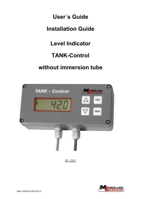
<strong>User´s</strong> <strong>Guide</strong><br />
<strong>Installation</strong> <strong>Guide</strong><br />
<strong>Level</strong> <strong>Indicator</strong><br />
TANK-Control<br />
without immersion tube<br />
02 / 2012
Contents<br />
1 System description ........................................................ 3<br />
1.1 Fitting instructions ....................................................................................... 4<br />
1.2 Display unit with sensor ............................................................................... 4<br />
1.2.1 Fitting / general indications .............................................................................. 7<br />
1.3 Automatic fill stop with Safi ball valve ........................................................ 9<br />
1.3.1 Operating device and UNI-Control S ............................................................... 9<br />
1.3.2 Schwitching-off with ISO-jobcomputer........................................................... 10<br />
2 Operating instructions ................................................. 11<br />
2.1 Calibration ................................................................................................... 11<br />
2.1.1 Basic initialisation process ............................................................................ 11<br />
2.1.2 The tank table is already stored in the memory (see appendix) .................... 12<br />
2.1.3 The tank table is not yet stored in the memory .............................................. 13<br />
2.2 Operation ..................................................................................................... 17<br />
2.3 Calibration table .......................................................................................... 18<br />
3 Tips for trouble-shooting on the TANK-Control ........ 19<br />
4 Technical data ............................................................... 20<br />
5 Appendix to the operating instructions ..................... 20<br />
5.1 List of bord computer that support TANK-Control .................................. 20<br />
5.2 List of Diagrams .......................................................................................... 20<br />
5.3 List of Tables ............................................................................................... 20<br />
5.4 Tank type table ............................................................................................ 21<br />
Page - 2 - Copyright <strong>Müller</strong>-<strong>Elektronik</strong> GmbH & Co. KG TANK-Control User's <strong>Guide</strong> (02/12)
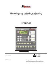
Operating device<br />
Front panel<br />
Increase key<br />
Display Decrease key<br />
1 System description<br />
The level indicator TANK-Control facilitates volume measurement with various types<br />
of tanks. It is applied mainly in agriculture for liquid fertilizer application and plant protection.<br />
The device operates with all aqueous solutions, even if their specific densities<br />
vary to that of water. By means of calibration it is possible to use different as well<br />
as irregular shaped tanks. The calibration values for the most common standard<br />
tanks are stored in the computer of the operating device. The measured values (tank<br />
content) can be retrieved from the ME bord computer 1 as required. When the pre-set<br />
amount is reached, the filling is switched off by the ME bord computer (provided the<br />
machine has been prepared for this purpose).<br />
1 An overview of the ME bord computers can be found in the appendix (see 5.1 page 20)<br />
Calibration key<br />
Quit-key<br />
Copyright <strong>Müller</strong>-<strong>Elektronik</strong> GmbH & Co. KG TANK-Control User's <strong>Guide</strong> (02/12) Page - 3 -
1.1 Fitting instructions<br />
1.2 Display unit with sensor<br />
The level indicator has the following parts:<br />
- <strong>Level</strong> sensor with operating device<br />
- 1 float<br />
- 1 flange -140<br />
- 1 Viton gasket -140<br />
- 4 Viton gaskets - 25x8x3<br />
- 4 hexagon screws - M 8x35<br />
- 4 nuts - M8<br />
- 4 nuts - M8 flat<br />
- 8 spring washers - B8<br />
- 8 washers - A8.4 (large)<br />
- 4 washers - A8.4<br />
- 1 tube socket<br />
- 2 Viton gaskets - 25x6<br />
- 1 nut - M6 (self-locking)<br />
- 1 washer 24.2x12.2<br />
- 1 washer A6.4<br />
- 1 locking ring<br />
Page - 4 - Copyright <strong>Müller</strong>-<strong>Elektronik</strong> GmbH & Co. KG TANK-Control User's <strong>Guide</strong> (02/12)
Diagr. 1-1 Replacement parts overview<br />
Copyright <strong>Müller</strong>-<strong>Elektronik</strong> GmbH & Co. KG TANK-Control User's <strong>Guide</strong> (02/12) Page - 5 -
Diagr. 1-2 TANK-Control fitting parts overview<br />
Page - 6 - Copyright <strong>Müller</strong>-<strong>Elektronik</strong> GmbH & Co. KG TANK-Control User's <strong>Guide</strong> (02/12)
1.2.1 Fitting / general indications<br />
Before drilling into the tank, check first that there is enough room for the immersion<br />
tube inside the tank and that there is no obstruction caused either by pipes or struts.<br />
The function of the Tank-Control level sensor can only be guaranteed when it is installed<br />
vertically. With the aid of the installation diagram, carry out the following<br />
steps:<br />
1. First of all, using the flange bore 4 holes (8.5 mm diameter) in order to secure<br />
the flange and the 55 mm opening.<br />
2. Bore a hole in the base of the tank (6.2 mm diameter) to take the tube holder.<br />
Determine the position for boring by means of a plumb bob, proceeding from<br />
the centre of the opening on the tank lid. In this way the vertical installation of<br />
the sensor tube is guaranteed.<br />
3. Mount the tube socket as illustrated in the mounting diagram.<br />
4. Mount the flange (1), Viton gasket (2), float (3) (point the float with the front<br />
surface marked with an "O" towards the cable outlet) in that order on to the<br />
sensor tube and secure with a washer (4) and a security ring (5) to avoid slipping.<br />
Carefully loosen the security ring using security ring pliers as far as required<br />
so that it can be screwed over the screw thread.<br />
5. Once the sensor tube has been assembled as described above lead it through<br />
the opening in the tank lid and screw it into the tube socket on the base of the<br />
tank.<br />
6. Mount the flange using M8 hexagon screws.<br />
7. In order to simplify dismantling, should this be necessary, take the cable from<br />
the operating device and secure the surplus cable in a loop near the sensor<br />
tube with cable ties. When dismantling always disconnect the cable on the sensor<br />
tube.<br />
Copyright <strong>Müller</strong>-<strong>Elektronik</strong> GmbH & Co. KG TANK-Control User's <strong>Guide</strong> (02/12) Page - 7 -
Connecting the operating device<br />
Connect the operating device to the power supply of the tractor, so that the maximum<br />
voltage (13.8V) cannot be exceeded.<br />
The cable has the following connections:<br />
white ground<br />
brown + 12 V power supply<br />
green signal output for ME bord computer<br />
Do not use a high-pressure cleaner to clean the sensor or operating<br />
device<br />
Do not open the operating device. The warranty is no longer valid<br />
once the seal is broken:<br />
Please observe the following points when opening devices which are no longer<br />
covered by warranty.<br />
- Once the lid of the casing has been opened tighten the screws again carefully<br />
in order to avoid the lid becoming distorted.<br />
- When changing cables or opening PG screw plugs use a suitable sealant (e.g.<br />
non-ascetic silicone) to seal inside the cable screw plugs. Make sure that the<br />
earth claw always fits on the cable screw plug.<br />
Page - 8 - Copyright <strong>Müller</strong>-<strong>Elektronik</strong> GmbH & Co. KG TANK-Control User's <strong>Guide</strong> (02/12)
1.3 Automatic fill stop with Safi ball valve<br />
In connection with the UNI-Control S, the filling operation can be switched off when<br />
the pre-set amount has been reached. The safi ball valve (1 1/4", 1 1/2" or. 2") is fitted<br />
to the sprayer at a suitable point in the filling tube. The operating device is fitted<br />
near the ball valve.<br />
1.3.1 Operating device and UNI-Control S<br />
The operating device is connected in the manifold signal distribution box.<br />
After fitting the filling tube, the ball valve is always opened manually with the S1<br />
switch. A switch-off delay of 10 seconds guarantees that the ball valve fully opens,<br />
as the ball valve can only be closed from a completely open position.<br />
When the required amount has been reached, the UNI-Control S puts out a pulse via<br />
the control line d16 and the ball valve slides shut. The filling operation can also be<br />
stopped manually using the S1 switch.<br />
Diagr. 1-3 Fill stop operating device for UNI-Control S<br />
The operating device can be ordered with the part no.: 302528.<br />
(1) Switch S1<br />
(2) Connection cable to<br />
switch box<br />
(3) Grommet for connection<br />
cable of ball valve<br />
Copyright <strong>Müller</strong>-<strong>Elektronik</strong> GmbH & Co. KG TANK-Control User's <strong>Guide</strong> (02/12) Page - 9 -
1.3.2 Schwitching-off with ISO-jobcomputer<br />
The operating device for ISOBUS-ECUs can be connected to the wire harness<br />
with a 6 pin AMP connector. An extention cable is available for machines with<br />
junction box.<br />
The ball valve is connected directly to the operating device.<br />
The operating device can be ordered with part number: 30252820. The extension<br />
cable has part number: 30303280.<br />
Diagr. 1-4 Fill stop operating device for ISOBUS ECUs<br />
For operating instructions of the fill stop function please refer to the instruction<br />
book of the ISOBUS ECU.<br />
Page - 10 - Copyright <strong>Müller</strong>-<strong>Elektronik</strong> GmbH & Co. KG TANK-Control User's <strong>Guide</strong> (02/12)
2 Operating instructions<br />
2.1 Calibration<br />
Before initial operation, the Tank-Control requires the tank table (level of tank content).<br />
Up to 20 calibrations per tank can be carried out. This means that even the<br />
contents of irregular sized tanks can be recorded. For some tanks (see appendix) the<br />
table has already been stored in the memory. In this case calibration is not necessary.<br />
All that is required here is a 100l alignment.<br />
2.1.1 Basic initialisation process<br />
To ensure that the level indicator functions correctly a basic initialisation is to be<br />
carried out prior to initial operation.<br />
Basic initialisation is also to be carried out<br />
if "0000" appears on the display when the device is switched on. Proceed as follows:<br />
1. The float must be in the lowest end position (tank empty otherwise pull out the<br />
immersion tube).<br />
2. Press the keys and simultaneously (ca. 3s) until "8888" appears on<br />
the display. Release the keys. Basic initialisation is now completed.<br />
3. If the immersion tube was pulled out, mount it correctly once more.<br />
Switch off the device after basic initialisation has been completed. If "0000" appears<br />
on the display when the device is switched on repeat the procedure. Beforehand<br />
check that the float really is at the bottom of the immersion tube.<br />
If after switch-on "0000" still appears on the display, then there is a fault in the device.<br />
Copyright <strong>Müller</strong>-<strong>Elektronik</strong> GmbH & Co. KG TANK-Control User's <strong>Guide</strong> (02/12) Page - 11 -
2.1.2 The tank table is already stored in the memory (see appendix)<br />
After the installation has been completed, the type of tank can be entered according<br />
to the table.<br />
Preparation<br />
- set up the field sprayer in a horizontal position<br />
- open the tank outlet<br />
- fill with water until it runs out of the tank outlet<br />
- turn off the flow of water and as soon as water is no longer running out of the<br />
tank outlet, close it.<br />
Switch on the device<br />
The length in cm, which the level indicator in use can measure, appears for a short<br />
time on the display.<br />
Select tank setting<br />
- press and hold the key Cal.<br />
-press key<br />
-release keys<br />
A C, a small circle and an arrow appear on the left-hand side of the display, on the<br />
right-hand side a number flashes; this number corresponds to the pre-set tank number.<br />
(see appendix).<br />
Select the type of tank<br />
- select the number of the tank being used from the tank table (appendix)<br />
- with the key<br />
set the tank number<br />
or<br />
- press the key Quit.<br />
The operating mode "tank content" is activated, the characters on the left-hand side<br />
of the display (C, circle and arrow) disappear. The tank content is displayed (in litres).<br />
100 litres calibration<br />
The 100 litres calibration must be carried out, as small variations can occur in the<br />
height of the tanks.<br />
- fill the tank with 100 litres of water<br />
- press the key<br />
and the key Quit. simultaneously.<br />
A corrected value followed by the 100 litre voIume display is shown. The device is<br />
now calibrated to a tank content of 100 litres.<br />
Page - 12 - Copyright <strong>Müller</strong>-<strong>Elektronik</strong> GmbH & Co. KG TANK-Control User's <strong>Guide</strong> (02/12)
2.1.3 The tank table is not yet stored in the memory<br />
During the calibration process, the measured values delivered from the level sensor<br />
are combined and stored with the current level of the tank in use, which has already<br />
been recorded in the operating device.<br />
The calibration process is carried out in 6 stages<br />
1. Select tank number 0<br />
2. Select operating mode tank calibration<br />
3. Enter "tank empty"<br />
4. Calibration step 1<br />
In this process the smallest tank content, which can be measured by the Tank-<br />
Control, is determined using the operating device. As soon as a measurement can<br />
be established by the sensor, a C appears on the display. The first stage can be<br />
calibrated.<br />
5. Calibration steps 2 - 19<br />
Use an accurate flow meter or vehicle scales when filling up the tank with water<br />
gradually. An incrementation (amount filled between 2 calibration steps) of a<br />
twentieth of the total volume is recommended. To ensure an accurate display of<br />
the level the incrementation should not exceed a tenth of the total volume.<br />
However a calibration step for an accurate 100 l alignment must lie at exactly<br />
100 l. The incrementation does not have to remain constant, i.e. following calibration<br />
steps are possible: 0 l, 50 l, 100 l, 300 l, 500 l whilst a maximum of 20<br />
calibration steps can be stored.<br />
Please note that the calibration of the last calibration step can only be carried<br />
out when the tank is completely full.<br />
3 stages, which are repeated for each calibration step, are required for the calibration:<br />
1. enter the calibration step (first column in the calibration table, see appendix)<br />
2. enter the current filled content<br />
3. enter the measured values displayed in the calibration table<br />
For the checking and documentation of the calibration process, the calibration values<br />
are entered into a copy of the table provided in the appendix.<br />
6. End the calibration process<br />
Copyright <strong>Müller</strong>-<strong>Elektronik</strong> GmbH & Co. KG TANK-Control User's <strong>Guide</strong> (02/12) Page - 13 -
Tank calibration process<br />
Preparation<br />
- set up the field sprayer in a horizontal position<br />
- open the tank outlet<br />
- fill with water until it runs out of the tank outlet<br />
- turn off the flow of water and as soon as water is no longer running out of the tank<br />
outlet close the tank outlet.<br />
Select tank number 0 (self-calibrated tank)<br />
- press and hold key Cal.<br />
- press key<br />
- release keys<br />
A C, a small circle and an arrow appear on the left-hand side of the display simultaneously,<br />
on the right-hand side a number flashes; this number corresponds to the<br />
preset tank number.<br />
- with key<br />
- press key Quit.<br />
set tank number 0<br />
The tank number 0 has been selected.<br />
Set operating mode tank calibration<br />
- switch the device off and on<br />
- press and hold Cal.<br />
- press key Quit.<br />
- release keys<br />
- A C (calibration) appears on the left-hand side of the display, on the right-hand<br />
side a "0" flashes.<br />
Page - 14 - Copyright <strong>Müller</strong>-<strong>Elektronik</strong> GmbH & Co. KG TANK-Control User's <strong>Guide</strong> (02/12)
Enter empty tank<br />
Empty the tank<br />
- press key Quit.<br />
- 0 (0 litres) appears on the display.<br />
- press key Quit.<br />
- the measured value appears on the display (enter in the table)<br />
- press key Quit.<br />
0 (calibration step 0) flashes on the display.<br />
Before entering each measured value allow any ripples in the tank to<br />
subside.<br />
Calibration step 1<br />
- calibration step 0 (flashing) shows on the display.<br />
- key<br />
- 1 flashes on the display (calibration step 1)<br />
- press key Quit.<br />
0 (0 litre tank content) appears on the display<br />
Fill the tank slowly until the `C´ appears on the left-hand side of the screen<br />
stop filling (as a rule, a first measurement can be recorded with the calibra-<br />
tion step 0. In this case 0 litres tank content must be set for calibration step<br />
1 as well. Go on with calibration step 2).<br />
- press<br />
to set the current tank content in litres<br />
- press key Quit.<br />
- the level of the filling is displayed (5 or 0 as last position) in mm (enter in to<br />
table)<br />
press key Quit.<br />
1 flashes on the display (calibration step 1)<br />
The calibration step 1 determines the smallest value which can be measured.<br />
Copyright <strong>Müller</strong>-<strong>Elektronik</strong> GmbH & Co. KG TANK-Control User's <strong>Guide</strong> (02/12) Page - 15 -
- Calibration steps 2 to max. 19<br />
preceding calibration steps are displayed<br />
- with the key<br />
- press key Quit.<br />
set the next calibration step<br />
- calibration step is stored, the content (litres) of the preceding calibration<br />
step is displayed<br />
- fill the tank with the set amount of water (next step size)<br />
- (calibration step 2 = 100 litres !)<br />
- with the keys enter the new content<br />
(enter in table).<br />
- press key Quit.<br />
- tank content is stored, the new tank value is displayed<br />
(enter in table).<br />
- Press key Quit.<br />
- measurement is stored<br />
The calibration can be carried out in the opposite direction in the same way, i.e.<br />
whereby a full tank is emptied. Make sure that in this case the process starts with<br />
calibration step 19 and a full tank.<br />
End calibration process<br />
The calibration process can be interrupted as well as ended after completion. After<br />
an interruption, the calibration process can be continued at the appropriate calibration<br />
step. In both cases the calibration process is ended by pressing two keys simultaneously<br />
as described below. Please note that both keys have to be pressed at<br />
the highest calibrated step, as this value has been set as the current upper limit<br />
of the level.<br />
- press and hold key Cal.<br />
- press key Quit.<br />
The operating mode "tank content" is activated, the C disappears, the tank content is<br />
displayed<br />
Page - 16 - Copyright <strong>Müller</strong>-<strong>Elektronik</strong> GmbH & Co. KG TANK-Control User's <strong>Guide</strong> (02/12)
2.2 Operation<br />
After switching on the device the current measuring capacity of the sensor in use is<br />
displayed for a short time and then the tank content appears. If the number 9999 appears<br />
on the display, this means that the maximum permissible level has been exceeded.<br />
This function is used as a safety guard. If the ME bord computer recognises the<br />
9999l signal, it switches off the filling process, independent of the pre-set rate. Similarly,<br />
an overflow resulting from a false entry (e.g. tank content= 3000 l - value entered<br />
= 4000 l) can be avoided.<br />
If a UNI-Control S is used, answer the question to the "tank capacity - Imp./l" enter<br />
"1".<br />
Copyright <strong>Müller</strong>-<strong>Elektronik</strong> GmbH & Co. KG TANK-Control User's <strong>Guide</strong> (02/12) Page - 17 -
2.3 Calibration table<br />
Tab. 2-1 example of a calibration table<br />
Calibration<br />
step<br />
Filled content<br />
litres<br />
0 0 10<br />
1 30 15<br />
2 100 155<br />
3 350 325<br />
4 500 430<br />
5<br />
6<br />
Measured<br />
value<br />
The figures measured during calibration can be entered in Tab. 2-2. Please enter<br />
also the tank type.<br />
Tab. 2-2 Calibration table for self calibrated tank<br />
Tank type:<br />
Calibration Standard capaci-<br />
step ty<br />
Liter<br />
0 0<br />
1<br />
2<br />
3<br />
4<br />
5<br />
6<br />
7<br />
8<br />
9<br />
10<br />
11<br />
12<br />
13<br />
14<br />
15<br />
16<br />
17<br />
18<br />
19<br />
Measured value<br />
Page - 18 - Copyright <strong>Müller</strong>-<strong>Elektronik</strong> GmbH & Co. KG TANK-Control User's <strong>Guide</strong> (02/12)
3 Tips for trouble-shooting on the TANK-Control<br />
Problem Cause Solution<br />
The length of the sensor<br />
determined during the<br />
switch-on diagnostics differs<br />
from the actual<br />
measured length of the<br />
level sensor used. (e.g. 0<br />
or 556)<br />
Faulty cable connection<br />
between operating device<br />
and sensor.<br />
Sensor or operating device<br />
is defective<br />
9999 displayed The float is not on the<br />
sensor or the float is installed<br />
the wrong way<br />
round<br />
"0000" displayed at<br />
switch-on<br />
During tank calibration<br />
values are determined in<br />
the calibration steps<br />
which are lower than the<br />
previous values<br />
Float magnets are demagnetised<br />
max. filling limit exceeded<br />
Float is outside the<br />
measuring area<br />
Check cable connection<br />
and if necessary repair<br />
Replace sensor tube. If<br />
still faulty send in the<br />
complete device for repair.<br />
Install float<br />
Turn float<br />
Replace float<br />
False values in EEPROM Carry out basic initialisation.<br />
If error remains send<br />
in the complete device for<br />
repair<br />
Movement of the float on<br />
the sensor tube due to<br />
ripples in the tank<br />
Wait for the ripples to<br />
subside before storing<br />
values<br />
Copyright <strong>Müller</strong>-<strong>Elektronik</strong> GmbH & Co. KG TANK-Control User's <strong>Guide</strong> (02/12) Page - 19 -
4 Technical data<br />
Tab. 4-1 Technical data<br />
Power supply: 10.5 V – 16 V<br />
Temperature range: -20 °C – 50 °C<br />
Casing: Durable Aluminium<br />
Safety class: IP 65<br />
Measurements<br />
operating unit:<br />
175 mm x 110 mm x 60 mm (WxHxD)<br />
5 Appendix to the operating instructions<br />
5.1 List of bord computer that support TANK-Control<br />
Only display of tank content<br />
- SPRAYDOS<br />
- LBS-Control<br />
- ECO-Terminal with ECO field sprayer ECU<br />
Display of tank content and automatic fill stop<br />
- UNI-Control S<br />
- BASIC-Terminal with ISOBUS field sprayer ECU<br />
- BASIC-Terminal TOP with ISOBUS field sprayer ECU<br />
5.2 List of Diagrams<br />
Diagr. 1-1 Replacement parts overview ................................................................................................................. 5<br />
Diagr. 1-2 TANK-Control fitting parts overview ................................................................................................... 6<br />
Diagr. 1-3 Fill stop operating device for UNI-Control S ....................................................................................... 9<br />
Diagr. 1-4 Fill stop operating device for ISOBUS ECUs ..................................................................................... 10<br />
5.3 List of Tables<br />
Tab. 2-1 example of a calibration table ................................................................................................................ 18<br />
Tab. 2-2 Calibration table for self calibrated tank ................................................................................................ 18<br />
Tab. 4-1 Technical data ........................................................................................................................................ 20<br />
Tab. 5-1 Tank type table Version: 07.10.2010 ..................................................................................................... 21<br />
Page - 20 - Copyright <strong>Müller</strong>-<strong>Elektronik</strong> GmbH & Co. KG TANK-Control User's <strong>Guide</strong> (02/12)
5.4 Tank type table<br />
Tab. 5-1 Tank type table Version: 07.10.2010<br />
Tank number Company / Tank name Capacity (Liter)<br />
0 selbstgeeichtes Faß<br />
1 Dammann 2800 3000<br />
2 Holder- ASP 2700<br />
3 Dammann 4000 4000<br />
4 Schmotzer- ASP 2500<br />
5 Dammann 3000 3000<br />
6 Jacoby Eurotrain 2500 2500<br />
7 Amazone UG 3000 3000<br />
8 Sieger HD 5000 5000<br />
9 Amazone UF 1200 1200<br />
10 Dubex 3000<br />
11 Hoegen Diekhoff 3000<br />
12 SIEGER HD 3500 3500<br />
13 Dammann 2000 ohne Einb. 2000<br />
14 AGROTRONIX 475 475<br />
15 TECNOMA 4200 4200<br />
16 Dammann 5000 5000<br />
17 Kundenfaß 12000<br />
18 Sieger TSMR 3000<br />
19 Sieger TSMR 3600<br />
20 Sieger TSMR 4200<br />
21 Inuma ITAS Bauf. Z ab Bj. 2002 3500<br />
22 Inuma IAS bis Bj. 1999 4500<br />
23 Inuma IAS bis Bj. 1999 4000<br />
24 Inuma IUAS Bauf. C bis Bj. 1999 2000<br />
25 Sieger HD 3500<br />
26 Lemken Eurotrain TC 2600 2600<br />
27 Jacoby Eurotrac 2000 l 2000<br />
28 Bartoud 3200 l 3200<br />
29 Agrevo 200<br />
30 Agrevo 1000<br />
31 Lemken Eurotrain TC 3500 3500<br />
32 Alys (Vicon) 3500<br />
33 HARDI TZ 3500 3500<br />
34 Amazone UG 3000<br />
3000<br />
anderer Einbau als Faß 7<br />
35 Beyne 3700 3700<br />
36 Beyne 2700 2700<br />
37 BBG 3300<br />
38 Amazone UG 4500 4500<br />
39 Inuma IUAS Bauf. I 2000<br />
40 Inuma IUAS Bauf. I 3000<br />
41 Inuma IUAS Bauf. I 3500<br />
42 Inuma ITAS Bauf. R ab Bj. 2002 4000<br />
43 Inuma ITAS Bauf. R ab Bj. 2002 5000<br />
44 Jacoby Eurotrac 2000<br />
45 Dammann 2900 2900<br />
Copyright <strong>Müller</strong>-<strong>Elektronik</strong> GmbH & Co. KG TANK-Control User's <strong>Guide</strong> (02/12) Page - 21 -
Tank number Company / Tank name Capacity (Liter)<br />
46 EEFTING 5500L 5500<br />
47 AGREVO 50L<br />
50<br />
48 DUBEX Junior 2400<br />
49 DUBEX Nestor 3100<br />
50 DUBEX Mentor 4255<br />
51 Sieger TSMR 5000 5000<br />
52 EEFTING 4200<br />
53 EEFTING 3000<br />
54 EEFTING 3800<br />
55 DUBEX Stentor 6750<br />
56 Dammann 5000i gerade 5000<br />
57 Dammann 4000i gerade 4000<br />
58 Amazone UG2200 2200<br />
59 John Deere Typ 638 3800<br />
60 Schmotzer ASP 3800 3800<br />
61 Dammann 5800 gerade 5800<br />
62 HARDI COMMANDER 4200 4200<br />
63 HARDI COMMANDER 2800 2800<br />
64 HARDI COMMANDER 3200 3200<br />
65 nicht belegt<br />
66 DAMMANN 7000i gerade 7000<br />
67 DUBEX Modell 8 1100<br />
68 EEFTING 3300<br />
69 Lemken Eurotrain TC 5000 5000<br />
70 SCHMOTZER ASP 2700 2700<br />
71 DUBEX Vector 3200L 3200<br />
72 nicht belegt<br />
73 BBG SF430 3400<br />
74 BBG SF430 4000<br />
75 EEFTING 7200L 7200<br />
76 RTS – Albatros 35 3200<br />
77 DUBEX Modell 8 700<br />
78 DUBEX Nestor 900<br />
79 EEFTING 5600L 5600<br />
80 RTS – Albatros 45 4250<br />
81 RTS – Albatros 55 5480<br />
82 nicht belegt<br />
83 EEFTING 3800L FUSEE 3800<br />
84 RTS Albatros 65 6450<br />
85 RTS Spritze 40 4100<br />
86 EEFTING 2700L 2700<br />
87 EEFTING 3300L 3300<br />
88 DAMMANN FEA 15035 15000<br />
89 EEFTING 4200L 4200<br />
90 RTS Albatros 25 2400<br />
91 Dubex Aufbau 3000<br />
92 Inuma IAS Evo 3500<br />
93 Inuma IAS Evo 4000<br />
94 Inuma IAS Evo 4500<br />
Page - 22 - Copyright <strong>Müller</strong>-<strong>Elektronik</strong> GmbH & Co. KG TANK-Control User's <strong>Guide</strong> (02/12)
Tank number Company / Tank name Capacity (Liter)<br />
95 Inuma IAS Evo 5000<br />
96 Inuma IAS K 2000<br />
97 Inuma IAS K 2500<br />
98 Inuma IAS K 3000<br />
99 Inuma IUAS Bauf.C ab Bj. 2000 2000<br />
100 Lemken Albatros 30 3000<br />
101 Lemken Albatros 40 4000<br />
102 DAMMANN 4000i mME 4000<br />
103 Inuma IAS Evo 6000<br />
104 BBG S340 4000<br />
105 DAMMANN 4500li 4500<br />
106 Lemken Albatros 50 5000<br />
107 Inuma 3000l Fa.Reich 3000<br />
108 DUBEX 12500 12500<br />
109 DUBEX Modell 8 900<br />
110 DUBEX Junior 1900l 1900<br />
111 Lemken Albatros 60 6000<br />
112 EEFTING Deichsel 2700l / 2004 2700<br />
113 DAMMANN 4000i schräg 4650<br />
114 DAMMANN 4500i schräg 4650<br />
115 DAMMANN 4000i mME schräg 4580<br />
116 EEFTING Deichsel 4200l / 2004 4200<br />
117 Lemken Eurotrain TC 6000 6400<br />
118 EEFTING Deichsel 5600l / 2004 5600<br />
119 DAMMANN 5000i schräg 5000<br />
120 Lemken Primus 35 3500<br />
121 Lemken Primus 45 4500<br />
122 Inuma IAS Creation 3500 3500<br />
123 DAMMANN 8000i schräg 8000<br />
124 EEFTING Deichsel 3000/2005 3000<br />
125 EEFTING Deichsel 3800/2004 3800<br />
126 EEFTING Radlenkung 5500/2005 5500<br />
127 EEFTING Radlenkung 4300/2005 4300<br />
128 Inuma IAS 4000 Fa. Hollweck (U 400) 4000<br />
129 EEFTING 3300l Fusee model(2005) 3300<br />
130 Dammann 4000SK gerade 4000<br />
131 Inuma 3000l Fa.Zunhammer 3000<br />
132 Inuma 3000l Fa.Lätzsch 3000<br />
133 Inuma ITAS 4500l Fa.Zunhammer 4500<br />
134 Agrifac GNS 4200 4200<br />
135 Agrifac ZA 2700 2700<br />
136 EEFTING 4200 Deichsel Model 2006 4200<br />
137 EEFTING 2700 Deichsel Model 2006 2700<br />
138 EEFTING 3800/3900 Knik Model 2006 3800/3900<br />
139 COSMO 4000 3850<br />
140 MAP II HIDRO 3500 H 3500<br />
141 MAP II 3000 F 3000<br />
142 AGRIO M3000 3400<br />
143 AGRIO M3500 3970<br />
144 AGRIO M4000 4700<br />
Copyright <strong>Müller</strong>-<strong>Elektronik</strong> GmbH & Co. KG TANK-Control User's <strong>Guide</strong> (02/12) Page - 23 -
Tank number Company / Tank name Capacity (Liter)<br />
145 AGRIO M6000 6745<br />
146 ABEMEC 3100 3100<br />
147 DUBEX 12500 (Anzeigewert*10) 12500<br />
148 AGRIO 5000 5250<br />
149 Schmotzer 2000 Aufbau 2050<br />
150 Agrio 3800 4000<br />
151 Ag Chem RG 618-A / 5000 5500<br />
152 EEFTING Deichsel 6000 6150<br />
153 Agrifac GNS 5800 5900<br />
154 Inuma 3000l CHEMO Farm-Star 3000<br />
155 Inuma 4000l CHEMO Farm-Star 4000<br />
156 Inuma 3500l Lätzsch IUAS 3500<br />
157 Lemken Primus 25 2510<br />
158 Dubex Actor 5000 5650<br />
159 Lemken Albatros 20 2050<br />
160 DAMMANN 3000i 3450<br />
161 DAMMANN 5000i S 5300<br />
162 DAMMANN 5000 i m ME 5550<br />
163 DAMMANN 6000i S 6565<br />
164 DAMMANN 10000 i m ME 11200<br />
165 DAMMANN 10000i 11000<br />
166 DUBEX Junior 2400/2008 2400<br />
167 Knight Muller Tank 3500l SP GRP 3500<br />
168 Knight 3800l 3955<br />
169 Agrifac GNS 7200 7160<br />
170 AGRIO 3500 CZ 3600<br />
171 AGRIO 4000 CZ 4200<br />
172 Lemken Sirius 900 970<br />
173 Lemken Sirius 1300 1400<br />
174 Lemken Sirius 1600 1700<br />
175 Lemken Sirius 1900 2000<br />
176 Agrio 2500 2625<br />
177 Agrio 8000 8250<br />
178 Inuma Marathon 10000 11200<br />
179 Inuma Marathon 13000 14400<br />
180 CAFFINI Prestige 5500 5500<br />
181 DAMMANN 7000i S 7650<br />
182 EEFTING Knik D3600 3800<br />
183 EEFTING Knik D3000 3400<br />
184 Bräutigam HAS45 4500<br />
185 DAMMANN 8000i schräg 2009 8760<br />
186 Knight Self Propelled 3500l GRP 3550<br />
187 Knight EUA 3000l GRP 3100<br />
188 Knight EUA 4000L GRP 4100<br />
189 GABO 3000l 3050<br />
190 DAMMANN 12000i 13350<br />
191 DAMMANN FEA8000 8800<br />
192 Inuma Professional Chemo 6000 - 09 6400<br />
193 Inuma Professional Chemo 7000 7600<br />
194 Inuma Professional Chemo 8000 8500<br />
Page - 24 - Copyright <strong>Müller</strong>-<strong>Elektronik</strong> GmbH & Co. KG TANK-Control User's <strong>Guide</strong> (02/12)
Tank number Company / Tank name Capacity (Liter)<br />
195 Inuma Marathon 10000 Zun. 10600<br />
196 DAMMANN 2000 MBP 2200<br />
197 DAMMANN 5800 RRW 6250<br />
198 DAMMANN 6000i meRRW 6700<br />
199 DAMMANN 6000i S2010 6700<br />
200 DAMMANN 12000i RRW 13350<br />
201 Agrio 3000 Tiger 3150<br />
202 Agrio TC 7000 7300<br />
203 Agrio 2000 Tiger 2100<br />
204 DAMMANN 5000 is RRW 5600<br />
205 DAMMANN 6000 is RRW 6800<br />
206 DAMMANN 8000 i RRW 8900<br />
207 DAMMANN 4000 i GN 4500<br />
208 DAMMANN 4000 ime GN 4500<br />
209 DAMMANN 4000 ime RRW GN 4700<br />
210 DAMMANN 5000 i S2010 5650<br />
211 DAMMANN 5000i schräg RRW 5700<br />
212 DAMMANN 7000 is RRW 7800<br />
213 DAMMANN 8000 i GN 8850<br />
214 DAMMANN 8000i me RRW 8700<br />
215 DAMMANN 8000i schräg RRW 8700<br />
216 DAMMANN 10000 ime RRW 11700<br />
217 CAFFINI Prestige 3300 3300<br />
218 CAFFINI Prestige 5500 5500<br />
219 BOTALON TRASERO MAP II 2850<br />
2010<br />
2920<br />
220 BOTALON TRASERO MAP II 3250<br />
2010<br />
3310<br />
221 BOTALON DELANTERO MAP II 3250<br />
2010<br />
3270<br />
222 BOTALON TRASERO MAP II 3500<br />
2010<br />
3600<br />
223 BOTALON DELANTERO MAP II 3500<br />
2010<br />
3550<br />
224 BOTALON TRASERO MAP II HIDRO<br />
4030<br />
4000 2010<br />
225 AGRIO Dino 8000 8500<br />
226 TECNOMA TECNIS 3500 4060<br />
227 TECNOMA TECNIS 4500 4820<br />
228 TECNOMA TECNIS 6000 6520<br />
229 TECNOMA FORTIS 3300 3535<br />
230 TECNOMA FORTIS 4300 4750<br />
231 TECNOMA LASER PR2540 2760<br />
232 TECNOMA LASER PR3240 3500<br />
233 TECNOMA LASER PR4240 4660<br />
234 TECNOMA LASER PR5240 5610<br />
Copyright <strong>Müller</strong>-<strong>Elektronik</strong> GmbH & Co. KG TANK-Control User's <strong>Guide</strong> (02/12) Page - 25 -