serial communication controller (scc ™ sdlc mode of operation - Clips
serial communication controller (scc ™ sdlc mode of operation - Clips
serial communication controller (scc ™ sdlc mode of operation - Clips

Create successful ePaper yourself
Turn your PDF publications into a flip-book with our unique Google optimized e-Paper software.
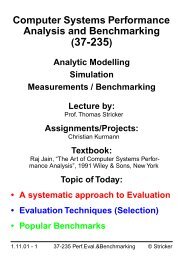
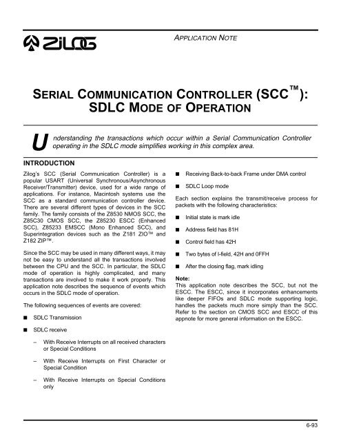
APPLICATION NOTE1SERIAL COMMUNICATION CONTROLLER (SCC ):SDLC MODE OF OPERATION 10Understanding the transactions which occur within a Serial Communication Controlleroperating in the SDLC <strong>mode</strong> simplifies working in this complex area.INTRODUCTIONZilog’s SCC (Serial Communication Controller) is apopular USART (Universal Synchronous/AsynchronousReceiver/Transmitter) device, used for a wide range <strong>of</strong>applications. For instance, Macintosh systems use theSCC as a standard <strong>communication</strong> <strong>controller</strong> device.There are several different types <strong>of</strong> devices in the SCCfamily. The family consists <strong>of</strong> the Z8530 NMOS SCC, theZ85C30 CMOS SCC, the Z85230 ESCC (EnhancedSCC), Z85233 EMSCC (Mono Enhanced SCC), andSuperintegration devices such as the Z181 ZIO andZ182 ZIP.Since the SCC may be used in many different ways, it maynot be easy to understand all the transactions involvedbetween the CPU and the SCC. In particular, the SDLC<strong>mode</strong> <strong>of</strong> <strong>operation</strong> is highly complicated, and manytransactions are involved to make it work properly. Thisapplication note describes the sequence <strong>of</strong> events whichoccurs in the SDLC <strong>mode</strong> <strong>of</strong> <strong>operation</strong>.The following sequences <strong>of</strong> events are covered:■SDLC Transmission■■Receiving Back-to-back Frame under DMA controlSDLC Loop <strong>mode</strong>Each section explains the transmit/receive process forpackets with the following characteristics:■■■■■Initial state is mark idleAddress field has 81HControl field has 42HTwo bytes <strong>of</strong> I-field, 42H and 0FFHAfter the closing flag, mark idlingNote:This application note describes the SCC, but not theESCC. The ESCC, since it incorporates enhancementslike deeper FIFOs and SDLC <strong>mode</strong> supporting logic,handles the packets much more simply than the SCC.Refer to the section on CMOS SCC and ESCC <strong>of</strong> thisappnote for more general information on the ESCC.■SDLC receive– With Receive Interrupts on all received charactersor Special Conditions– With Receive Interrupts on First Character orSpecial Condition– With Receive Interrupts on Special Conditionsonly6-93
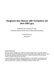
Application NoteSerial Communication Controller (SCC ): SDLC Mode <strong>of</strong> OperationSDLC TRANSMITFigure 1 shows the time chart for the transmitting SDLCpacket under interrupt control. When transmit is engaged,data is shifted out <strong>of</strong> the transmitter on the falling edge <strong>of</strong>the transmit clock. Transitions on the diagram are showncoincident with TxCLK fall — in actual practice, there aresome associated delay times (which are specified in thedata sheet).TxCLKTx DataOpening Flag Data 81H Data 42H Data 0FFH Data 42H CRC 0E013H Closing Flag Note 11Note 1Note 9/INTNote 3Note 6➘➘➘Note 4Note 5Note 7Note 8Note 10➘➘➘Note 2Figure 1. Typical SDLC Trsnsmission Sequence6-94
Application NoteSerial Communication Controller (SCC ): SDLC Mode <strong>of</strong> OperationNotes on Figure 1:1. The SCC has two possible idle states, Mark idle(contiguous logic 1) or Flag idle (repeating flag pattern7EH). In this figure, the SCC has to be switched to flagidle in order to send the opening flag <strong>of</strong> the frame.Care must be taken not to put the first data byte (in thiscase, address 81H) into the Transmit Buffer too soonafter the switchover from Mark idle to Flag idle hasbeen made; otherwise, the data may be loaded intothe Transmit Shift Register before the flag is loaded.To ensure that this cannot happen, a delay must beexecuted before the first data byte is put into thebuffer. The delay time is dependent on the data rateand a safe minimum duration is 8 bit-times.2. Transmit Buffer Empty Interrupt for 81H. At this pointthe data has just been transferred to the Transmit ShiftRegister and data 42H is written to the TransmitBuffer.3. The time between the first data byte being transferredto the Shift Register and the first bit appearing at theTxD pin is always six bit-times.4. Transmit Buffer Empty Interrupt for data 42H. Data0FFH is written to the Transmit Buffer at this point.5. Transmit Buffer Empty Interrupt for data 0FFH. Data42H is written to the Transmit Buffer at this point.6. The time between interrupts depends on the datacharacter length and the number <strong>of</strong> zero insertions inthe character. For 8 bits/character it can vary between8 and 10 bit-times. The particular instance showncorresponds to the single zero insertion when the byte0FFH is transmitted.7. Transmit Buffer Empty Interrupt for data 42H. Sincethis is the last byte to be transmitted, the ResetTransmit Interrupt Pending command is issuedinstead <strong>of</strong> writing another byte to the Transmit Buffer.8. Transmitter Underrun/EOM Interrupt. This occurswhen both the Transmit Shift Register and theTransmit Buffer are empty. It is an External/Statusinterrupt. The data sent when this occurs issummarized in the table below:1Abort/Flag on Tx Underrun/EOM Latch DataUnderrun bit State when Underrun occurs Sent0 Reset CRC and Flag1 Reset Abort and Flag0 Set Flags1 Set Flags9. The transmitted CRC is 16 bits long provided thatthere are no zero insertions. In theory it could be aslong as 19 bits.10. The last interrupt generated occurs after the CRC isshifted out <strong>of</strong> the transmitter and a flag is loaded to besent. It is a Transmit Buffer Empty Interrupt. If anotherframe is to be transmitted, the first character <strong>of</strong> thenext frame can be loaded. The two frames will then beseparated by a single flag (Back-to-back frame).11. If the SCC is set up for mark on idle and a newcharacter is not loaded when the last interrupt occurs,only a single flag is sent.6-95
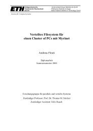
Application NoteSerial Communication Controller (SCC ): SDLC Mode <strong>of</strong> OperationSDLC RECEIVEThere are several different ways to receive a SDLC packeton the SCC; by polling, by Interrupts and by DMA. TheSCC has the following four Receive Interrupt Modes:■■Disabled. This should be used in the Polling <strong>mode</strong>.Interrupts on all received characters or SpecialConditions. This <strong>mode</strong> should be used for normalinterrupt-driven <strong>operation</strong>.Status FIFO can give byte count and error status withoutinterrupting data transfer <strong>operation</strong>s.Each <strong>of</strong> the four cases is covered in this application noteexcept Receive Interrupt disabled. For polling, the basic<strong>operation</strong> is identical to that used for “interrupt on allcharacters or Special Condition” <strong>mode</strong>. Instead <strong>of</strong> waitingfor an interrupt, polling Reads Registers to determine ifservice is needed or not.■■Interrupts on First Character or Special Condition. This<strong>mode</strong> is intended for received data transfer by the DMA,and enables the DMA when the interrupt is received bythe First Character <strong>of</strong> the packet.Interrupt on Special Condition only. This <strong>mode</strong> allowsthe DMA to free-run and keep transferring data to thebuffer. This is an ideal <strong>mode</strong> for the CMOS SCC as wellas the ESCC with Status FIFO enabled, because theOn the SCC, data is sampled by the receiver on the risingedge <strong>of</strong> the receive clock. Set-up and hold times for RxDwith respect to RxC are specified in the productspecifications.In general, receiver status changes are triggered by RxC.In the following Figures, they are shown as beingcoincident with this edge — in actual practice, there aresome associated delay times (which are specified in thedata sheet).RECEIVE INTERRUPTS ON ALL RECEIVE CHARACTERS OR SPECIAL CONDITIONSSCC is placed in this <strong>mode</strong> by programming Bit D4-3 <strong>of</strong>WR1 to 10. Once programmed in this <strong>mode</strong>, the SCCgenerates interrupts whenever character(s) are in thereceive buffer or when Special Conditions occur. This<strong>mode</strong> is the most common <strong>operation</strong>al <strong>mode</strong>.Notes on Figure 2:1. The receiver is usually in hunt <strong>mode</strong> when waiting fora frame. When the opening flag is received, anExternal/Status Interrupt is generated, indicating thechange from hunt <strong>mode</strong> to sync <strong>mode</strong>.2. The /SYNC output follows the state <strong>of</strong> the sync registercomparison output. The comparison is done on a bitby bit basis, so the /SYNC pin is only active for one bittime./SYNC goes active one bit-time after the last bit<strong>of</strong> the sync character is sampled at the RxD pin.3. A Receive Character Available Interrupt is generated11 bit-times 8 bits for the shifter and a 3-bit delay) afterthe last bit <strong>of</strong> the character is sampled at the RxD pin.The status bits corresponding to that character mustbe read before the data character is read from theReceive Buffer. This interrupt is for data 81H.4. Receive Character Available Interrupt for data 42H.5. Receive Character Available Interrupt for data 0FFH.6. Receive Character Available Interrupt for data 42H.7. Receive Character Available Interrupt for the first CRCbyte. The SCC treats the CRC as data, since the SCCdoes not yet distinguish a difference between CRCand data!8. The closing flag is recognized two bit-times before thesecond CRC byte is completely assembled in theReceive Shift Register. As soon as it is recognized, aSpecial Condition interrupt is generated. The EOF bitis set at this point and the CRC error bit can bechecked. The six least significant bits <strong>of</strong> the secondCRC byte are present at the top <strong>of</strong> the first CRC byte.The status information must be read before thesecond CRC byte is read from the buffer. The CRCbytes should be discarded. The CRC checker isautomatically reset for the next frame.9. External/Status interrupt for the Sync/Hunt change.This occurs when the SCC recognizes an Abort(Marking line) and forces the receiver into hunt <strong>mode</strong>.The SCC can be programmed so that the Abort itselfgenerates an interrupt if required. If flag idle was set,this interrupt will not occur.6-96
Application NoteSerial Communication Controller (SCC ): SDLC Mode <strong>of</strong> Operation1RxCLKNote 9 ➘Rx DataOpening Flag Data 81H Data 42H Data 0FFH Data 42H CRC 0E013H Closing FlagNote 9/INT Note 3Note 1 Note 3Note 4Note 5Note 6Note 7Note 8➘➘➘➘➘➘➘/SYNC➘Note 2Figure 2. Typical SDLC Receive Sequence with Receive Interrupts on all ReceivedCharacters or Special Condition6-97
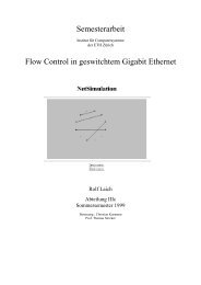
Application NoteSerial Communication Controller (SCC ): SDLC Mode <strong>of</strong> OperationRECEIVE INTERRUPTS ON FIRST CHARACTER OR SPECIAL CONDITIONSThe sequence <strong>of</strong> events in this <strong>mode</strong> is similar to that in“Receive Interrupts on all received characters and SpecialConditions”, except that it generates Receive CharacterInterrupt on the first received character only, andsubsequent data is read by the DMA.The SCC is placed in this <strong>mode</strong> by programming Bit D4-3<strong>of</strong> WR1 to 01. Once programmed in this <strong>mode</strong>, the SCCgenerates interrupts when it receives the First Character <strong>of</strong>the packet or a Special Condition occurs. This <strong>mode</strong> is for<strong>operation</strong> with the DMA. On the interrupt for the firstreceived character, DMA is enabled. On SpecialConditions (either End-<strong>of</strong>-Message, overrun, or Parityerror, — parity on the SDLC is not normal, however), theservice routine stops the DMA and starts over again.RxCLKRx DataOpening Flag Data 81H Data 42H Data 0FFH Data 42H CRC 0E013H Closing FlagNote 9/INTNote 3➘Note 1Note 3Note 10Note 12➘➘Note 5Note 7➘Note 6Note 8➘➘➘➘/W//REQ (In /REQ <strong>mode</strong>)/SYNC➘➘Note 4Note 9➘Note 11➘Note 2Figure 3. Typical SDLC Receive Sequence with Receive Interrupts on First Character or Special Condition6-98
Application NoteSerial Communication Controller (SCC ): SDLC Mode <strong>of</strong> OperationNotes on Figure 3:1. The receiver is usually in hunt <strong>mode</strong> when waiting fora frame. When the opening flag is received, anExternal/Status Interrupt is generated, indicating thechange from hunt <strong>mode</strong> to sync <strong>mode</strong>.2. The /SYNC output follows the state <strong>of</strong> the sync registercomparison output. The comparison is done on a bitby bit basis, so the /SYNC pin is only active for one bittime./SYNC goes active one bit-time after the last bit<strong>of</strong> the sync character is sampled at the RxD pin.3. A Receive Character Available Interrupt is generated11 bit-times after the last bit <strong>of</strong> the character issampled at the RxD pin. In this <strong>mode</strong>, enable the DMAon this interrupt. This interrupt is for data 81H.4. If SCC’s DMA request function has been enabled,/REQ becomes active here.5. DMA request for data 42H.6. DMA request for data 0FFH.7. DMA request for data 42H.8. DMA request for the first CRC byte. The SCC treatsthe CRC as data, since the SCC does not yetdistinguish a difference between CRC and data!9. DMA request for the second CRC byte. The closingflag is recognized two bit-times before the secondCRC byte is completely assembled in the ReceiveShift Register. As soon as it is transferred to theReceive Buffer, it generates a DMA request.10. This interrupt is EOF (End <strong>of</strong> Frame), a SpecialCondition interrupt. This will not occur until the DMAhas read the 2nd CRC byte from the Receive Buffer.When it occurs, the Receive Buffer is locked and nomore DMA requests can be generated until theReceive Buffer is unlocked by issuing the Error Resetcommand. Before issuing this command, all <strong>of</strong> thestatus bits required (e.g., the CRC error status) mustbe read, and the last two bytes read by the DMAdiscarded. The enable interrupt on next ReceiveCharacter command must be sent to the SCC so thatthe next character (i.e., the First Character <strong>of</strong> the nextframe) will produce an interrupt. If this is not done, thecharacter will generate a DMA request, not aninterrupt.Should a Special Condition occur within the datastream (i.e., for a condition other than EOF) the /INTpin will not go active until the character with theSpecial Condition has been read by the DMA.11. DMA request for 2nd CRC bytes. This occurs whenthe EOF interrupt service routine has not disabled theDMA function <strong>of</strong> the SCC, and did not read the dataafter unlocking the buffer by issuing an Error Resetcommand.12. External/Status Interrupt for the Sync/Hunt change.This occurs when the SCC recognizes an Abort(Marking line) and forces the receiver into hunt <strong>mode</strong>.The SCC can be programmed so that the Abort itselfgenerates an interrupt if required. If flag idle was set,this interrupt would not occur.16-99
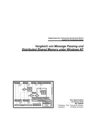
Application NoteSerial Communication Controller (SCC ): SDLC Mode <strong>of</strong> OperationRECEIVE INTERRUPTS ON SPECIAL CONDITIONS ONLYThe sequence <strong>of</strong> event in this <strong>mode</strong> is similar to that for“Receive Interrupts on first received character or SpecialCondition,” except it will not generate Receive CharacterAvailable interrupt at all. This <strong>mode</strong> is designed for<strong>operation</strong>s where the DMA is pre-programmed, or theapplication does not have enough time to set up DMAtransfer on First Character interrupt.The SCC is placed in this <strong>mode</strong> by programming Bit D4-3<strong>of</strong> WR1 to 11. Once programmed in this <strong>mode</strong>, the SCCgenerates interrupts when Special Conditions occur. OnSpecial Condition (either End-Of-Message oroverrun/Parity error, if enabled), corrective action can betaken for that packet.The SDLC Frame Status Buffer (not available on theNMOS version) is very useful in this <strong>mode</strong>. First <strong>of</strong> all, setDMA to transfer several packets. The SDLC Frame StatusBuffer holds information which tells you how many byteswere in the received packet and reports whether or noterror conditions (overrun/CRC error/parity error) haveoccurred.The sequence <strong>of</strong> events in this <strong>mode</strong> is identical to the“Receive Interrupts on First Character or SpecialCondition” <strong>mode</strong> (Figure 3); Note 3, however, does notapply, and Note 4 should read as follows for this case:Note 4 in Receive Interrupts on Special Condition only<strong>mode</strong>:DMA request for data 81H. The DMA function <strong>of</strong> the SCCshould be enabled by this time frame.RECEIVING BACK TO BACK FRAME IN RECEIVE INTERRUPTS ON SPECIAL CONDITIONONLY MODE“Back to Back” frame means there are two framesseparated with only one flag — the closing flag <strong>of</strong> theprevious packet also acts as the opening flag <strong>of</strong> thefollowing packet. Receiving such packets is identical toreceiving a single packet, except that the sequence <strong>of</strong>events happens in a short time around the shared flag.Assuming SCC is running under Receive Interrupts onSpecial Condition only <strong>mode</strong> (under DMA Control), atypical sequence <strong>of</strong> events is shown in Figure 4. It isidentical to that used for “Receive Interrupts on SpecialCondition Only” <strong>mode</strong>, with the addition <strong>of</strong> anotherfollowing packet.Notes on Figure 4:1. DMA request data before 0FFH.2. DMA request for data 0FFH.3. DMA request for data 42H.4. DMA request for the first CRC byte. The SCC treatsthe CRC as data, since the SCC does not yetdistinguish a difference between CRC and data!5. DMA request for the second CRC byte. The closingflag is recognized two bit-times before the secondCRC byte is completely assembled in the ReceiveShift Register. As soon as it is transferred to theReceive Buffer, it generates a DMA request.6. This interrupt is EOF (End <strong>of</strong> Frame), a SpecialCondition Interrupt. This will not occur until the DMAhas read the 2nd CRC byte from the Receive Buffer.When it occurs the Receive Buffer is locked and nomore DMA requests can be generated until theReceive Buffer is unlocked by issuing the Error Resetcommand. Before this command is issued, all <strong>of</strong> thestatus bits required (e.g., the CRC error status) mustbe read, and the last two bytes read by the DMAdiscarded. The Enable Interrupt on Next ReceiveCharacter command must be sent to the SCC so thatthe next character (i.e., the First Character <strong>of</strong> the nextframe) will produce an interrupt. If this is not done, thecharacter will generate a DMA request, not aninterrupt.On unlocking the Receive Buffer after the EOFinterrupt, no initialization is required with respect to thereceiver. All characters have been removed by theDMA and the receiver is ready for the next frame.While the Buffer is locked the SCC can receive 2 7/8characters (8 bits/character) before there is a danger<strong>of</strong> the receiver overrunning. The only way that this canbe specified is by referencing it to the falling edge <strong>of</strong>the request for the last CRC byte. This time is a worstcase minimum <strong>of</strong> 33 bit-times (possibly more if thereare any characters with inserted zeros). As soon asthe Buffer is unlocked an additional 8 (minimum) bittimesbecome available because the top byte <strong>of</strong> theBuffer is freed up.7. DMA request for second CRC byte. This occurs whenthe EOF interrupt service routine has not disabled theDMA function <strong>of</strong> the SCC, and fails to read the dataafter unlocking the FIFO by issuing Error Resetcommand.8. DMA request for data 01H.9. MA request for data 03H.6-100
Application NoteSerial Communication Controller (SCC ): SDLC Mode <strong>of</strong> Operation➘1RxCLKRx DataData 0FFH Data 42H CRC 0E013H Closing/OpeningFlag/INTNote 1Note 3➘Note 2Note 4Note 6➘/W//REQ (In /REQ <strong>mode</strong>)➘➘➘/SYNCData 01H Data 03H Data 07HNote 5Note 8➘Note 7Note 9➘➘Figure 4. Receiving “Back to Back” frame with Receive Interrupts on Special ConditionOnly Mode (DMA Controlled)6-101
Application NoteSerial Communication Controller (SCC ): SDLC Mode <strong>of</strong> OperationTHE SDLC LOOP MODEThe SDLC Loop <strong>mode</strong> is one <strong>of</strong> the protocols used in thering configuration network topology. The typical networkconfiguration is shown in Figure 5. As shown, there is oneMaster (or primary) station and several slave (orsecondary) stations. This figure does not have a clockconnection, but each station’s transmit clock must besynchronized to the master SCC. This can be done byfeeding the clock using a separate clock line, or by usingPhase Locked Loop (PLL) to recover the clock.Master SCCTxRxRxTxRxTxRxTxSlave SCC #1Slave SCC #2Slave SCC #nFigure 5. SDLC Loop Mode ConfigurationThis <strong>mode</strong> is similar to the normal SDLC <strong>mode</strong>, other thanthat secondary stations are not allowed to freely send outpackets. When a secondary station wants to send apacket, it needs to wait for a special pattern to be received.The pattern is called EOP (End Of Poll), and consists <strong>of</strong> a0 followed by seven 1s on the transmission line (as data, itis 11111110). This pattern resembles the SDLC Flagpattern (7EH; 0111110), except the last bit has beenchanged to a 1 thus turning this pattern into a flag.Upon network initialization, secondary station TxD andRxD connections use gate propagation delay. On the firstEOP, a secondary station inserts one bit -time delaybetween RxD and TxD, and relays RxD input to TxD.When it has a message to send out, it waits for an EOP.When it detects EOP in this phase, it changes the last bit<strong>of</strong> the EOP to zero, making it a Flag, then begins to sendits own message. From this point on, normal SDLCtransmission <strong>mode</strong>s apply. Packets conclude with Markidle, identifying it as an EOP pattern. The secondarystation then reverts back to one bit delay <strong>mode</strong>.Figure 6 illustrates this <strong>mode</strong>’s sequence <strong>of</strong> events. Tosimplify the example, this figure assumes there is oneMaster station and one Slave station. If there are moreSlave stations, there will be additional one bit time delayper station after the network has initialized for loop <strong>mode</strong><strong>of</strong> <strong>operation</strong>.6-102
Application NoteSerial Communication Controller (SCC ): SDLC Mode <strong>of</strong> Operation42h 0ffh 42h CRC81hNote 10EOPNote 5EOPNote 9Note 4 Note 7 0aah 55h 55h 0aah CRCNote 3Note 6 Note 8Ext/Stat(Break/Abort Set)➘➘➘➘➘➘RCA➘Tx UnderrunTxBE TxBERCA RCA RCA RCA➘Ext/Stat(Break/Abort clr)Ext/Stat(Break/Abort set)Sp. CondTxBE➘RCA RCA RCA RCA RCA➘➘➘➘Sp. Cond➘RCA➘RCA➘RCA➘RCA➘RCA➘➘➘➚TxBE➘TxBE➘TxBESp. CondRCA: Receive Character Available InterruptTxBE: Tx Buffer Empty Interrupt1TxD (Master), RxD (Slave)EOPNote 1TxD (Slave)Note 2/INT (Slave)➘Figure 6. SDLC Loop ModeExt/Stat(Break/Abort set)/INT (Master)6-103
Application NoteSerial Communication Controller (SCC ): SDLC Mode <strong>of</strong> OperationTHE SDLC LOOP MODE (Continued)Notes on Figure 6:1. The master SCC sends EOP by switching from flag onidle to mark on idle2. At initialization, all Slave stations were set up for SDLCloop <strong>mode</strong> At this point, the Slave station connects itsRxD pin to TxD pin with gate propagation delay, andstarts to monitor Rx data for the EOP sequence.3. On receiving the EOP, the slave generates anExternal/Status Interrupt with Break/Abort bit set. Aone bit time delay is inserted between RxD and TxD.(The GAOP,Go active on Poll, bit should be reset atthis point to avoid unexpected loop entry by the Slavetransmitter.) The Slave’s on-loop bit is set and thereceiver is in hunt <strong>mode</strong>.4. Note that there is a one bit time delay betweenreceived data and transmitted data.5. When the Slave wants to transmit it must first receivean EOP and have GAOP set.6. On receiving an EOP, the Slave interrupts withBreak/Abort clear. The EOP is converted to a flag, theloop sending bit is set, and the transmitter will sendflags until data is written into the Transmit Buffer.7. Note that the flags overlap.8. When the slave has sent all <strong>of</strong> its data the GAOP flagshould be cleared so that the CRC is sent onunderrun.9. When the closing flag has been sent the Slave revertsto a one bit delay, which produces another EOP.10. The master must keep its output marking until itsreceiver has received all frames sent by secondaries.CMOS SCC AND ESCCThe discussion above applies to the NMOS SCC and theCMOS SCC without the SDLC Frame Status FIFO feature.The CMOS version and the ESCC have a SDLC FrameStatus FIFO for easier handling <strong>of</strong> the SDLC <strong>mode</strong> <strong>of</strong><strong>operation</strong>. The SDLC Status FIFO is designed for DMAcontrolled SDLC receive for high speed SDLC datatransmission, or for systems whose CPU interruptprocessing is not fast.This FIFO is able to store up to 10 packets’ worth <strong>of</strong> bytecount (14-bit count) and status information(Overrun/Parity/CRC error status). To use this feature,simply enable this FIFO and let DMA transfer data tomemory. While DMA is transferring received data to thememory, the CPU will check the FIFO and locate the datain memory, as well as the status information <strong>of</strong> thereceived packet.Other ESCC enhancements make it easier to handle theSDLC <strong>mode</strong> <strong>of</strong> <strong>operation</strong>. These include:■■■■■■■■■Deeper FIFO (4 Bytes Transmit, and 8 Bytes receive)Automatic Opening Flag transmissionAutomatic EOM resetAutomatic /RTS deactivationFast /DTR//REQ <strong>mode</strong>Complete CRC receptionReceive FIFO Antilock featureProgrammable DMA and interrupt request levelImproved data setup time specificationFor more details on these functions, please refer to theSCC/ESCC Technical manual and related documents.CONCLUSIONThis application note describes the basic <strong>operation</strong> <strong>of</strong> theSCC in SDLC <strong>operation</strong>al <strong>mode</strong>s. With minor variations,most <strong>of</strong> these <strong>operation</strong>s also apply to the CMOS SCCwith Status FIFO enabled and the ESCC.6-104