PMT50Ex-V2_0-00- Prospekt - Martens Elektronik GmbH
PMT50Ex-V2_0-00- Prospekt - Martens Elektronik GmbH
PMT50Ex-V2_0-00- Prospekt - Martens Elektronik GmbH

Create successful ePaper yourself
Turn your PDF publications into a flip-book with our unique Google optimized e-Paper software.
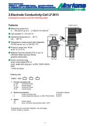
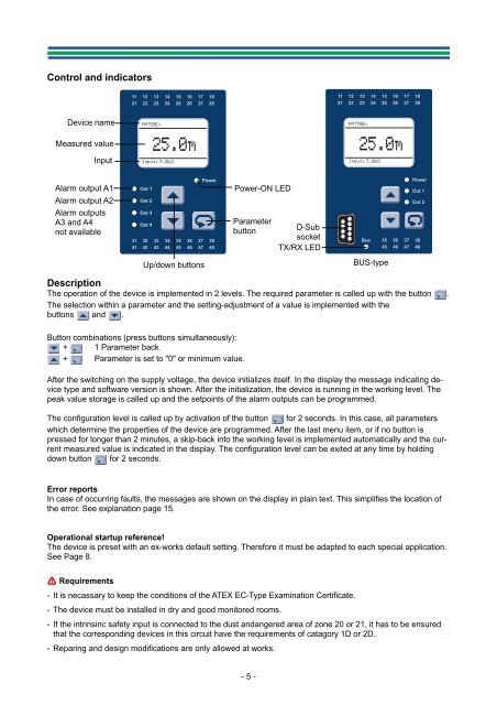
Control and indicatorsDevice nameMeasured valueInputAlarm output A1Alarm output A2Alarm outputsA3 and A4not availableUp/down buttonsPower-ON LEDParameterbuttonD-SubsocketTX/RX LEDBUS-typeDescriptionThe operation of the device is implemented in 2 levels. The required parameter is called up with the button .The selection within a parameter and the setting-adjustment of a value is implemented with thebuttons and .Button combinations (press buttons simultaneously):+ 1 Parameter back+ Parameter is set to "0" or minimum value.After the switching on the supply voltage, the device initializes itself. In the display the message indicating devicetype and software version is shown. After the initialization, the device is running in the working level. Thepeak value storage is called up and the setpoints of the alarm outputs can be programmed.The configuration level is called up by activation of the button for 2 seconds. In this case, all parameterswhich determine the properties of the device are programmed. After the last menu item, or if no button ispressed for longer than 2 minutes, a skip-back into the working level is implemented automatically and the currentmeasured value is indicated in the display. The configuration level can be exited at any time by holdingdown button for 2 seconds.Error reportsIn case of occurring faults, the messages are shown on the display in plain text. This simplifies the location ofthe error. See explanation page 15.Operational startup reference!The device is preset with an ex-works default setting. Therefore it must be adapted to each special application.See Page 8.$ Requirements- It is necassary to keep the conditions of the ATEX EC-Type Examination Certificate.- The device must be installed in dry and good monitored rooms.- If the intrinsinc safety input is connected to the dust andangered area of zone 20 or 21, it has to be ensuredthat the corresponding devices in this circuit have the requirements of catagory 1D or 2D.- Reparing and design modifications are only allowed at works.- 5 -