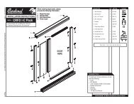
Cardinal Installation Instructions - Cardinal Shower Enclosures
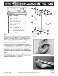
Cardinal Installation Instructions - Cardinal Shower Enclosures
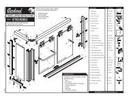
Cardinal Installation Instructions - Cardinal Shower Enclosures

You also want an ePaper? Increase the reach of your titles
YUMPU automatically turns print PDFs into web optimized ePapers that Google loves.
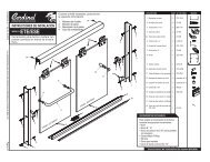
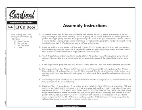
Updated: May 2007 ©2007 <strong>Cardinal</strong> <strong>Shower</strong> <strong>Enclosures</strong> Page 87SHOWER ENCLOSURESAssembly <strong>Instructions</strong>ModelCFCD DoorWhen ordering repair parts,please provide the followinginformation:1. Model Number2. Part Number3. Part Description4. ColorAssembly <strong>Instructions</strong>1. To assemble shower door, lay door glass on assembly table allowing the glass to overlap glass supports. If you areusing obscure glass, face smooth surface up. You will be glazing the top, bottom and handle rail with the glass in thisposition. Now apply glazing vinyl (item #1) to glass starting in the center of the glass on the handle side and continueit around the glass notching for corners (see detail A) and ending back in the center of the handle side. Smooth vinyl tothe glass then cut back 1 ½”on both ends, leaving a 3” gap for the handle.2. Center top and bottom rails (items 4 and 5) on ends of glass. If door is a hinge right, bottom rail (with overhead andscrew holes facing up) will go on your left. If hinge left the bottom rail will go on your right. Gently drive rails on with ablock of hardwood and steel hammer. A hinge right door is shown in sketch.3. Check 3” gap between ends of vinyl. Center handle rail (item #2) on glass (magnet facing up) and gently drive railonto vinyl. Now turn door around so that the handle rail is against the stops with the inside of bottom rail still facingup.4. Center hinge rail and gently drive onto vinyl. Secure all corners with #8 x 1 1/4” lead point screws (item #6) provided.5. Slip hinge jamb sleeve (item #7) over ball of hinge jamb (item #8) (see sketch B). Set hinge bushing (item #9) overhinge clip (item #10) and push hinge pin (item #11) into hinge rail. Drive the clip with bushing into the bottom end ofthe hinge jamb. Place hinge sleeve, clip, bushing and pin in place inside the hinge rail (screw hoes in jamb facing up)(detail B).6. Slip second pin in place in the hinge rail at the top of the door. Place the bushing over the clip and rive the clip into thehinge jamb securing the pin in the bushing.7. Start three #6 x 1/4” screws (item #12) into bottom rail. Insert splash vinyl (item #13) and drip trough (item #14) intothe bottom rail. Splash vinyl should butt up to magnetic strip at one end, and flush off with outside edge of hinge rail atthe other end (NEVER LET THE SPLASH VINYL GO BEYOND THE OUTSIDE EDGE OF THE HINGE RAIL). Flush off driptrough with notchback on bottom rail at latch side, push drip trough as far up as possible on latch side and as low aspossible on hinge side, push drip trough as far as possible on latch side and as low as possible on hinge side andsecure by tightening the three #6 x 1/4” screws. Insert drip plug (item #15) into the end of the drip trough at handlerail side. Water should now drain back into shower when the door is open.Assembly <strong>Instructions</strong>
Updated: May 2007 ©2007 <strong>Cardinal</strong> <strong>Shower</strong> <strong>Enclosures</strong> Page 88SHOWER ENCLOSURESAssembly <strong>Instructions</strong>ModelContinuous HingeWhen ordering repair parts,please provide the followinginformation:1. Model Number2. Part Number3. Part Description4. ColorContinuous Hinge
Updated: May 2007 ©2007 <strong>Cardinal</strong> <strong>Shower</strong> <strong>Enclosures</strong> Page 89SHOWER ENCLOSURESAssembly <strong>Instructions</strong>Model<strong>Cardinal</strong> SeriesWhen ordering repair parts,please provide the followinginformation:1. Model Number2. Part Number3. Part Description4. Color<strong>Cardinal</strong> Series FramedContinuous Hinge<strong>Shower</strong> Enclosure<strong>Installation</strong> <strong>Instructions</strong>NOTE: Wall channels are supplied at 67 3/4” for use in stall shower applications. For installation of door only, cut wall channels to66 5/8”, this will prevent wall channels from extending above the latch jamb.1. Hold wall channels, (item #17) in a plumb position and mark the three hole locations on the hinge side and bottomhole only on latch side. Drill holes in wall, using 3/16” carbide drill for the walls. Insert plastic screw anchor (item#18) into the drilled holes.2. Set wall channels in place and secure with the #8 x 1 1/4” screw (item #19) securing bottom screw only on latch side.NOTE: Your door is adjustable up to 1” (½”at hinge jamb & ½”at latch jamb).Example: A 24” door will fit an opening of 24” to 25”. The adjustment should also be used to correct out of plumb conditions.3. Set the latch jamb (item #20) in place over the wall channel but do not secure.4. Set the hinge jamb with the door attached in place over the wall channel. Adjust to fit the opening, mark and drill thethree screw holes with a #31 drill bit and secure using #6 x 3/8” screws (item #21).5. Slide the latch jamb over the wall channel, align the vertical surface of the latch jamb wit the vertical surface of thehandle rail of the door and mark the wall channel location on the wall. Remove the latch jamb, mark, drill and plugthe remaining two holes with the screw anchors, then secure with the #8 1 1/4” screws.6. Set the latch jamb over the wall channel and adjust it in or out until the desired tension is achieved by the magneticcatch, (about 3/16” margin between latch jamb and handle rail). Mark hole locations, drill wall channel, and secureusing three #6 x 3/8” screws.7. Adjust the drip trough up at the latch side of the door and down at the hinge side of the door so that the water willdrain back into the shower when the door is open. Adjust the splash vinyl to within 1/8” of the curb.NOTE: The splash vinyl should never be in direct contact with the curb.8. Run a bead of sealant the full length of both the wall channels on the inside of the stall shower where the wall channelsmeet the walls.<strong>Installation</strong> <strong>Instructions</strong>
Updated: May 2007 ©2007 <strong>Cardinal</strong> <strong>Shower</strong> <strong>Enclosures</strong> Page 90SHOWER ENCLOSURESAssembly <strong>Instructions</strong>ModelContinuous HingeWhen ordering repair parts,please provide the followinginformation:1. Model Number2. Part Number3. Part Description4. ColorContinuous Hinge
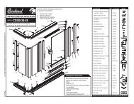
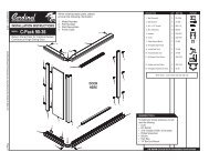
Updated: May 2007 ©2007 <strong>Cardinal</strong> <strong>Shower</strong> <strong>Enclosures</strong> Page 91SHOWER ENCLOSURES<strong>Installation</strong> <strong>Instructions</strong>CFCD UnitsModelWhen ordering repair parts,please provide the followinginformation:1. Model Number2. Part Number3. Part Description4. Color<strong>Cardinal</strong> Series FramedContinuous Hinge<strong>Shower</strong> EnclosureFramed <strong>Enclosures</strong>Breakdown Chart for Special Height and Width CFCD unitsSubtractPiecesUnit height -0 = ZD-3004 latch jamb height 1-0 = ZD-2505 hinge jamb height 1-0 = ZD-1006 wall channel height 2-7/8” = ZD-2503 hinge rail height 1-7/8” = ZD-1506 handle rail height 1-7/8” = ZV-955 hinge sleeve length 1Unit width -2-11/16” = ZD-1502 bottom rail length 1-2-11/16” = ZD-1501 top rail length 1-3-11/16” = ZD-1008 drip trough length 1Unit width -4-3/16” = Glass width 1Unit height -2-1/2” = Glass height 1DOOR SIZE AND METAL CHARTCFCD - Units Breakdown ChartNOTE: When possible use standard height door glass of 64-1/8”Model Opening ZD 1502ZD-1008 ZD-904 ZD-1501Number Size Glass Size Bottom Rail Drip Wiper Top RailCFCD-24 . . . . . . . . . . 24 to 25” . . . . . . . . . . 19-13/16” x _______ . . . . . . . . . . . 21-5/16”. . . . . . . . . . . . 20-5/16” . . . . . . . . . . . . 22” . . . . . . . . 21-5/16”CFCD-30 . . . . . . . . . . 25 to 26” . . . . . . . . . . 20-13/16” x _______ . . . . . . . . . . . 22-5/16”. . . . . . . . . . . . 21-5/16” . . . . . . . . . . . . 23” . . . . . . . . 22-5/16”CFCD-30 . . . . . . . . . . 26 to 27” . . . . . . . . . . 21-13/16” x _______ . . . . . . . . . . . 23-5/16”. . . . . . . . . . . . 22-5/16” . . . . . . . . . . . . 24” . . . . . . . . 23-5/16”CFCD-30 . . . . . . . . . . 27 to 28” . . . . . . . . . . 22-13/16” x _______ . . . . . . . . . . . 24-5/16”. . . . . . . . . . . . 23-5/16” . . . . . . . . . . . . 25” . . . . . . . . 24-5/16”CFCD-30 . . . . . . . . . . 28 to 29” . . . . . . . . . . 23-13/16” x _______ . . . . . . . . . . . 25-5/16”. . . . . . . . . . . . 24-5/16” . . . . . . . . . . . . 26” . . . . . . . . 25-5/16”CFCD-30 . . . . . . . . . . 29 to 30” . . . . . . . . . . 24-13/16” x _______ . . . . . . . . . . . 26-5/16”. . . . . . . . . . . . 25-5/16” . . . . . . . . . . . . 27” . . . . . . . . 26-5/16”CFCD-36 . . . . . . . . . . 30 to 31” . . . . . . . . . . 25-13/16” x _______ . . . . . . . . . . . 27-5/16”. . . . . . . . . . . . 26-5/16” . . . . . . . . . . . . 28” . . . . . . . . 27-5/16”CFCD-36 . . . . . . . . . . 31 to 32” . . . . . . . . . . 26-13/16” x _______ . . . . . . . . . . . 28-5/16”. . . . . . . . . . . . 27-5/16” . . . . . . . . . . . . 29” . . . . . . . . 28-5/16”CFCD-36 . . . . . . . . . . 32 to 33” . . . . . . . . . . 27-13/16” x _______ . . . . . . . . . . . 29-5/16”. . . . . . . . . . . . 28-5/16” . . . . . . . . . . . . 30” . . . . . . . . 29-5/16”CFCD-36 . . . . . . . . . . 33 to 34” . . . . . . . . . . 28-13/16” x _______ . . . . . . . . . . . 30-5/16”. . . . . . . . . . . . 29-5/16” . . . . . . . . . . . . 31” . . . . . . . . 30-5/16”CFCD-36 . . . . . . . . . . 34 to 35” . . . . . . . . . . 29-13/16” x _______ . . . . . . . . . . . 31-5/16”. . . . . . . . . . . . 30-5/16” . . . . . . . . . . . . 32” . . . . . . . . 31-5/16”CFCD-36 . . . . . . . . . . 35 to 36” . . . . . . . . . . 30-13/16” x _______ . . . . . . . . . . . 32-5/16”. . . . . . . . . . . . 31-5/16” . . . . . . . . . . . . 33” . . . . . . . . 32-5/16”CFCD-36 . . . . . . . . . . 36 to 37” . . . . . . . . . . 31-13/16” x _______ . . . . . . . . . . . 33-5/16”. . . . . . . . . . . . 32-5/16” . . . . . . . . . . . . 34” . . . . . . . . 33-5/16”
Updated: May 2007 ©2007 <strong>Cardinal</strong> <strong>Shower</strong> <strong>Enclosures</strong> Page 92SHOWER ENCLOSURES<strong>Installation</strong> <strong>Instructions</strong>CFCD UnitsModel<strong>Cardinal</strong> Series FramedContinuous Hinge<strong>Shower</strong> EnclosureWhen ordering repair parts,please provide the followinginformation:1. Model Number2. Part Number3. Part Description4. ColorBreakdown Chart for Special Height and Width CFCD stall units<strong>Shower</strong> door - 69” standard heightSubtractPiecesUnit height -2-3/8” = ZD-3004 latch jamb height ..............................1-2-3/8” = ZD-2505 hinge jamb height .............................1-1-1/4” = ZD-1006 wall channel height ...........................2-3-1/4” = ZD-2503 hinge rail height ................................1-3-1/4” = ZD-1506 handle rail height ..............................1-3-1/4” = ZV-955 hinge sleeve length...............................1Unit width -2-11/16” = ZD-1502 bottom rail length..............................1-2-11/16” = ZD-1501 top rail length ...................................1-3-11/16” = ZD-1008 drip trough length .............................1Unit width -4-3/16” = Glass width .....................................................1Unit height -4-7/8” = Glass height ....................................................1<strong>Shower</strong> door - 69” standard heightUnit width 0 = ZSS 3101 header & curb ..................................2Unit height -1-1/4” = ZD 1102 curb filler ..........................................2Unit height -1-1/4” = ZD 1103 inline post .........................................1Unit height -1-1/4” = ZSS 1104 90° post...........................................1Unit height -1-1/4” = ZSS 1105 135° post.........................................2NOTE: When possible use standard height door glass of 64-1/8”CFCD - Units Breakdown ChartParts List# ofItem # Pieces Part Number Part Description.1 1 ZV-540 16’ Glazing Vinyl2 1 ZD-1506 65 3/4” Handle rail (with/V-521A magnet)3 1 ZD-2503 65 3/4” Hinge rail4 1 ZD-1502 Bottom rail5 1 ZD-1501” Top rail6 4 #8 x 1 1/4” Lead point screws7 1 ZV-955 65 3/4” Hinge jamb sleeve8 1 ZD-2506 65 5/8” Hinge jamb9 2 ZD-1013 Hinge Bushing10 2 ZV-1009 1/2” Hinge clips11 2 ZV-945 Hinge pins12 3 #6 x 1/4” Pan head screws13 1 ZV-904 Splash vinyl14 1 ZD-1008 Drip trough16 2 ZD-3011 3” Handles17 2 ZD-1006 67 3/4” Wall channel18 6 ZV-935 Screw anchor19 6 #8 x 1 1/4” Pan head screws20 1 ZD-3004 66 5/8” Latch Jamb (with V-521A magnet)21 6 #6 x 3/8” Pan head screws
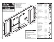
Updated: May 2007 ©2007 <strong>Cardinal</strong> <strong>Shower</strong> <strong>Enclosures</strong> Page 93SHOWER ENCLOSURES<strong>Installation</strong> <strong>Instructions</strong>ModelCRFD121413141213141312141356All doors are completely reversible and may beinstalled hinge-left or hinge-right. These illustrationsshow a hinge-right door hinging from the wall jamb.Other combinations are installed in a similar manner.To install your shower enclosure, you will need thefollowing:- Level- 3/32", 9/64" and 3/16" Drill Bits- Phillips Screwdriver8- Sealant- Hack Saw123491910111641411218178121212CRFD <strong>Installation</strong> <strong>Instructions</strong>99141414147513131313Item Description Qty Item # Picture1.2.3.4.5.6.7.8.9.10.11.12.13.14.15.16.17.18.19.20.Outside door handleInside door handle#6-32 x 1 3/4" FHMSSillWall channelsStrike jambHinge jambHinge pins#7 x 1 1/4" FH SMSDrip channelDrip channel plug#6 x 1/2" PH SMSWall anchors#8 x 1 1/2" OH SMSMagnetic stripsDrip channel vinylHinge glass frameHorizontal glass framesMagnetic glass frameGlazing vinylWhen ordering repair parts, please provide the part number,part name, model number, and specify a design, if any.1121211241111882112117’QS3439QS3440903CFM-70CFM-953CFM-954CFM-908EHB-17125CFM-49DP-312310NO240902M1354V1596CFM-907CFM-910CFM-983
Updated: May 2007 ©2007 <strong>Cardinal</strong> <strong>Shower</strong> <strong>Enclosures</strong> Page 94SHOWER ENCLOSURES<strong>Installation</strong> <strong>Instructions</strong>ModelCRFDStep 1! Assemble door handles by attaching outside doorhandle (1) and inside door handle (2) to door withtwo #6-32 x 1 3/4" flat head machine screws (3).(The inside door handle should be placed on themagnet side of the door.)Step 2! Measure the wall to wall opening of the shower.! Cut sill (4) 1/16" less than opening width.! Place sill on center of curb.! Set wall channels (5) firmly on sill (4) next to wall.Plumb and mark installation holes on wall.! Remove all parts. For ceramic tile installation, usea 3/16" masonry bit for drilling installation holesand install plastic wall anchors (13).! For fiberglass walls, drill 9/64" holes.Step 3! Place a bead of sealant on each end of curb underthreshold location.! Replace sill (4) in previous location.! Replace wall channels (5) and secure to wall witheight #8 x 1 1/2" pan head sheet metal screws(14).Craftsman SeriesHinge Door<strong>Installation</strong> Steps32Measure41451Step 4Step 5Step 6CRFD - <strong>Installation</strong> StepsThis door is reversible and can swing to the right or left.Decide which way you wish your door to swing. (Aright-swing door is shown.)! Cut hinge jamb (7) flush with top of door. Positionstrike jamb (6) over wall channel (5) with long sideto inside of shower.! Position hinge jamb (7) with door on opposite wallchannel (5).! Close door against strike jamb making sure door isflush against jamb and align door to opening.! Note: if magnet does not pull door shut, reverse! From inside the shower, secure strike jamb (6) towall channel by drilling 3/32" holes approximately3/8" from each end and in the center.! Secure with #6 x 1/2" pan head sheet metal screws(12).! Secure hinge jamb (7) to wall channel (5) bydrilling 3/32" holes approximately 3/8" from each! Insert drip channel vinyl (16) into drip channel(10) and trim to size.! Insert plastic drip channel plug (11) into endof drip channel.! With door closed, position drip channel oninside of door with a slope to the hinge side(7).! Mark the location, then clean door thoroughlywith rubbing alcohol.! Peel protective cover off of double face tapeand install drip channel to inside of door.! Drill three 3/32" holes from drip channel intodoor. IMPORTANT: Holes must be drilled aminimum of 1/2" below exposed glass.Step 7! Seal inside and outside of unit at any point unit meets wall and curb.71612Magnets1/8” Clearance1012121112
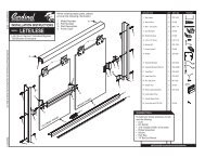
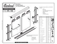
Updated: May 2007 ©2007 <strong>Cardinal</strong> <strong>Shower</strong> <strong>Enclosures</strong> Page 95SHOWER ENCLOSURES<strong>Installation</strong> <strong>Instructions</strong>ModelCRFSTo install your shower enclosure, you will need thefollowing:- Level- 3/32", 9/64" and 3/16" Drill Bits- Phillips Screwdriver- Sealant- Hack SawCRFS <strong>Installation</strong> <strong>Instructions</strong>Item Description Qty Item # Picture12345678910111213141516171819202122TrackWall jambsWall anchors#8 x 1 1/2" TH SMSBumpersHeaderRollers8-32 x 3/8" PH MSTowel bar brackets#6-32 x 1/2" TH MSTowel barsVinyl guide#6 x 3/8" FH SMSTrack silencerTempered glass (units)Glazing vinylHorizontal door framesVertical door frames#7 x 7/8" OH SMSRoller bracketsBy-pass door stopWall jamb guideWhen ordering repair parts, please provide the part number,part name, model number, and specify a design, if any.12662144442121234 ft.448412CFM-322CFM-279003CFM-7219850CFM-82828V622998CFM-6CFM-7CFM439302404
Updated: May 2007 ©2007 <strong>Cardinal</strong> <strong>Shower</strong> <strong>Enclosures</strong> Page 96SHOWER ENCLOSURES<strong>Installation</strong> <strong>Instructions</strong>Model CRFSStep 1! Measure the wall to wall opening on tub rim.! Cut track (1) 3/8" less than opening width.! Center vinyl guide (12) on track.! Using a 3/32" drill bit, drill holes and secure vinyl guide totrack with two #6 x 3/8" flat head machine screws (13).Step 2! Place track (1) on center of tub rim.! Set jambs (2) firmly in track (1) next to wall. Plumb and markinstallation holes on wall. Note: It is important that the walljambs are plumb.! If track does not fit flat, a slight bending of the track might beneeded.Step 3! Remove all parts. For ceramic tile installation, use a 3/16"masonry bit for drilling installation holes and install plasticwall anchors (3).! For fiberglass walls, use a 1/8" drill bit for drilling installationholes.Step 4! Apply a continuous bead of sealant to thebottom legs of track. A build up of sealant oneach end of the tub rim (where track is to fit)will be needed.! Replace track in previous location. Replacejambs (2) and secure to wall with six #8 x 11/2" truss head sheet metal screws (4). Note:Install bumpers with center installation screw.! Place wall jamb guides (22) near bottom ofeach wall jamb.Craftsman SeriesFramed BypassTub / <strong>Shower</strong> Enclosure<strong>Installation</strong> Steps42111Step 5Step 6Step 7CRFS - <strong>Installation</strong> Steps! Measure the wall to wall opening above the wall jambs.! Cut header (6) 1/16" less than opening.! Place header over jambs.Step 6! Attach rollers (7) to brackets (20) on top of doors withfour #8-32 x 3/8" pan head machine screws (SEMS) (8)as shown.! Lift inside door into header, placing rollers down in track.! Fit panel to wall by adjusting rollers. Note: Inside panel mustbe adjusted to the wall with the shower head.! Use the same procedure for outside door.! Insert towel bar brackets (9) into towel bar ends (11).! Insert #6-32 x 1/2" truss head machine screw (10)through door and into towel bar (11).! Install the by-pass door stop (21) on the inside of theoutside panel farthest from the shower head. It canalso be installed on the outside of the inside panelnext to the shower head.! Towel bar is to be attached to the outside of theoutside door and to the inside of the inside door toallow the doors to pass each other freely.Step 910 21! Seal inside and outside of unit at any point unit meets wall and curb, and where the jambs meetthe sill.911621109