Push Button R55F Series Fiber-Optic Color Mark Sensors - Multiprox
Push Button R55F Series Fiber-Optic Color Mark Sensors - Multiprox
Push Button R55F Series Fiber-Optic Color Mark Sensors - Multiprox

You also want an ePaper? Increase the reach of your titles
YUMPU automatically turns print PDFs into web optimized ePapers that Google loves.
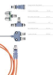
<strong>R55F</strong> <strong>Series</strong> <strong>Fiber</strong>-<strong>Optic</strong> <strong>Color</strong> <strong>Mark</strong> <strong>Sensors</strong>BPlastic fibersshown; procedureis identical forglass fibers<strong>Fiber</strong>ClipCAGlass <strong>Fiber</strong> Installation Procedure:1) Check to see that a rubber o-ring is pre-installed on each fiber control end.2) Slide the fiber clip to the open position (A).3) Insert one fiber end into each port (B). <strong>Push</strong> firmly on the fiber ends to compressthe o-rings and align the grooves in the fiber ends with the slot in the fiber clip.4) Slide the fiber clip back into place, locking the fibers into position (C).Plastic <strong>Fiber</strong> Installation Procedure:NOTE: <strong>R55F</strong> sensors accept 0.75, 1.0, and 1.5 mm (0.03", 0.04", and 0.06") corediameter plastic fibers.1) Cut the “control ends” (sensor ends) of the plastic fiber(s) to the desired lengthper the procedure which accompanies the fiber assembly.Figure 1. Installing fibers into the <strong>R55F</strong><strong>Series</strong> sensor2) If not already done, separate bifurcated fibers by approximately 2" from the controlends.3) Slide the fiber clip to the open position (A).4) Insert the fiber ends into each port and push them in as far as they will go (B).5) Slide the fiber clip back into place, locking the fibers into position (C).<strong>Fiber</strong> <strong>Optic</strong> Mounting ConsiderationsMount the sensing end of the fiber optic assembly so that the light image is totallycontained within the boundaries of the color mark to be sensed. The light image ismade smaller by moving the sensing tip closer to the surface of the material to besensed.When sensing marks on shiny (specular) materials, such as metal, plastic or glossypaper, mount the sensing tip of the fiber at approximately 15° from perpendicular tothe material surface to minimize strong direct reflections.Isolate the fiber mounting from vibration. Also, maintain mechanical stability of thesurface to be sensed (e.g., stabilize web flutter at the sensing point).Banner Engineering Corp. • Minneapolis, U.S.A.www.bannerengineering.com • Tel: 763.544.3164page 3