System Architecture Design
System Architecture Design
System Architecture Design

Create successful ePaper yourself
Turn your PDF publications into a flip-book with our unique Google optimized e-Paper software.
Project no: 100204pSHIELDpilot embedded <strong>System</strong>s arcHItecturE for multi-Layer Dependable solutionsInstrument type: Capability ProjectPriority name: Embedded <strong>System</strong>s / Rail Transportation Scenarios<strong>System</strong> <strong>Architecture</strong> <strong>Design</strong>For thepSHIELD-projectDeliverable D2.3.2Partners contributed to the work:HAI, GreeceSE, ItalyUNIROMA1, ItalyATHENA, Greece,THYIA, SloveniaETH, ItalySESM, Italy,CS, Portugal,CWIN, NorwayProject co-funded by the European Commission within the Seventh Framework Programme (2007-2012)Dissemination LevelPU Public XPP Restricted to other programme participants (including the Commission Services)RE Restricted to a group specified by the consortium (including the Commission Services)CO Confidential, only for members of the consortium (including the Commission Services)Issue 5Page i
Document Authors and ApprovalsAuthorsNameCompanyDateSignatureNikos PappasHAIAndrea MorgagniSEVincenzo SuraciUNIROMA1Kyriakos StefanidisATHENAAthanasios PoulakidasHAILjiljana MijićTHYIASpase DrakulTHYIAGordana MijicTHYIAPaolo AzzoniETHEmilio BisbiglioSESMJoão CunhaSESMPrzemyslaw OsochaSESMBaldelli RenatoSEAndrea FiaschettiUNIROMA1Jose VerissimoCSReviewed byNameCompanySpase DrakulTHYIANameJosef NollApproved byCompanyMASModification HistoryIssue Date DescriptionDraft A 26.10.2011 Issue for comments, connection to D2.3.1Issue 1 22.11.2011 SPD Requirements, InterfacesIssue 2 24.11.2011 Overlay additionsIssue 3 01.12.2011 Network Interfaces and ReviewIssue 4 09.12.2011 FinalIssue 5 10.01.2012 ApprovedIssue 6Issue 7Issue 5Page ii
Contents1 Executive Summary .................................................................. 122 Introduction ................................................................................ 133 Terms, Definitions and Approaches ........................................ 143.1 Cross-Layer / Cross-Overlay <strong>Architecture</strong> Definitions ............... 173.1.1 Introduction ....................................................................................... 173.1.2 Description of Cross-Layer <strong>Architecture</strong> ............................................ 193.1.3 The Overlay as a Cross-Layer Security <strong>Architecture</strong> forSecurity, Privacy and Dependability .................................................. 263.2 Node Layer Definitions ................................................................... 283.2.1 Nano and Micro/Personal Node ........................................................ 283.2.2 Power Node ...................................................................................... 333.2.3 Cryptography Technologies .............................................................. 353.3 Network Layer Definitions .............................................................. 383.3.1 General Network Layer description ................................................... 383.3.2 Software Defined Radio .................................................................... 393.3.3 Cognitive Radio ................................................................................. 403.4 Middleware Layer Definitions ........................................................ 413.4.1 SPD Driven Semantics ...................................................................... 423.4.2 Core SPD Services ........................................................................... 433.4.3 Policy-based Management ................................................................ 453.5 Overlay Layer Definitions ............................................................... 474 SPD Considerations .................................................................. 484.1 Fundamental Concepts .................................................................. 484.1.1 Security and Privacy ......................................................................... 484.1.2 Dependability .................................................................................... 504.2 Embedded <strong>System</strong>s ........................................................................ 534.2.1 Introduction ....................................................................................... 534.2.2 <strong>Design</strong> of Secure Embedded <strong>System</strong>s .............................................. 534.2.3 Cryptography and Embedded <strong>System</strong>s ............................................. 554.3 Applications ..................................................................................... 584.4 Preliminary Concept of pSHIELD Demonstrator<strong>Architecture</strong> ..................................................................................... 59Issue 5Page iii
4.4.1 <strong>System</strong> architecture for monitoring .................................................... 594.4.2 <strong>System</strong> architecture for Integration and Interoperation forIRIS ................................................................................................... 604.5 <strong>System</strong> <strong>Architecture</strong> SPD functionalities ..................................... 615 SPD Requirements .................................................................... 625.1 <strong>System</strong> <strong>Architecture</strong> Security Requirements ............................... 625.2 <strong>System</strong> <strong>Architecture</strong> Privacy Requirements ................................ 645.3 <strong>System</strong> <strong>Architecture</strong> Dependability Requirements ..................... 646 <strong>System</strong> <strong>Design</strong> ........................................................................... 666.1 Node Layer ....................................................................................... 666.1.1 Formal conceptual model .................................................................. 666.1.2 Nano and Micro/Personal node HW/SW ........................................... 766.1.3 Power node HW/SW ......................................................................... 836.2 Network Layer HW/SW .................................................................... 896.2.1 pSHIELD Network Layer and pSHIELD Network Adapter ................. 896.2.2 Components and Devices ................................................................. 916.2.3 Functions and Services ..................................................................... 936.2.4 Communication protocols .................................................................. 976.2.5 Interfaces .......................................................................................... 996.2.6 Security ............................................................................................. 996.3 Middleware Layer .......................................................................... 1016.3.1 Formalized conceptual model ......................................................... 1016.4 Overlay Layer ................................................................................. 1046.5 <strong>System</strong> Overall <strong>Architecture</strong> ........................................................ 1076.6 Interfaces ....................................................................................... 1176.6.1 Internal ............................................................................................ 1176.6.2 External ........................................................................................... 1186.6.3 Node ............................................................................................... 1186.6.4 Components .................................................................................... 1197 Conclusion ............................................................................... 1208 References ............................................................................... 121Issue 5Page iv
FiguresFigure 1 - A generic embedded system structure. .................................................................................... 14Figure 2 – a) Overview of the functional architecture of TISPAN NGN release 2, b) layered view of theTSPAN NGN architecture. ................................................................................................................. 16Figure 3 - Different kinds of cross-layer design proposals (boxes represent the protocol layers). ............ 20Figure 4 - Proposals for architectural blueprints for wireless communications. ......................................... 21Figure 5 - Proposed Cross-Layer Interaction Model ................................................................................. 22Figure 6 - Cross-layer adaptation and optimization in satellite network. ................................................... 25Figure 7 - Cross-layer architectures for indirect and direct communications. ............................................ 26Figure 8 – pSHIELD Overlay. ................................................................................................................... 27Figure 9 – Power Node pSHIELD component. ......................................................................................... 33Figure 10 - Network Layer: paradigm architecture. ................................................................................... 39Figure 11 – pSHIELD Middleware layer. .................................................................................................. 42Figure 12 – Typical IETF PBM <strong>Architecture</strong>. ............................................................................................. 45Figure 13– Dependability concept taxonomy. ........................................................................................... 51Figure 14 – Intelligent Wagon Infrastructure. ............................................................................................ 59Figure 15 – Integration & Interoperation concept of heterogeneous services. .......................................... 60Figure 16 - Formal conceptual model of pSHIELD SPD Node Layer. ....................................................... 67Table 1 - pSHIELD enabling technologies by node types. ....................................................................... 75Table 2 - pSHIELD services by node types. ............................................................................................ 76Figure 17 - Schematic view of SPD modules of a generic pSHIELD Nano, Micro and Personal Node. .... 78Table 3 - An example of the personal node SPD components. ................................................................ 78Figure 18 - Hardware architecture and nano node chip partitioning. ........................................................ 79Figure 19 - Concept model for security and dependability. ....................................................................... 82Figure 20 - Power Node board concept, with and without cooling heat sinks. .......................................... 84Issue 5Page v
Figure 21 - Power Node architecture: high level description. .................................................................... 86Figure 22 – Internal structure of an FPGA logic element. ......................................................................... 87Figure 23 - pSHIELD Network Layer: Adapter and Legacy....................................................................... 89Table 4 - Legacy Network Stack (802.11a).............................................................................................. 90Table 5 - Legacy Network Stack (Ethernet). ............................................................................................ 90Figure 24 - ESD and pSHIELD <strong>System</strong> layered view. .............................................................................. 91Figure 25 - Intelligent Wagon internal Network. ........................................................................................ 92Figure 26 – Network of connected devices (M2M platform). ..................................................................... 93Figure 27 – SDR evolution. ...................................................................................................................... 94Figure 28 – pSHIELD NETWORK ADAPTER conceptual model. ............................................................. 95Figure 29 – pSHIELD Network Adapter with some examples of exchanged information. ......................... 96Figure 30 – Core SPD services in the pSHIELD functional component architecture. ............................. 101Figure 31 – Core SPD services in the pSHIELD functional component architecture. ............................. 102Figure 32 – Details of the Discovery core SPD service. ......................................................................... 103Figure 33 – pSHIELD overlay: a functional view ..................................................................................... 105Figure 34 – Formalized conceptual model for pSHIELD Security Agent. ................................................ 106Figure 35 – Formalized conceptual model for the pSHIELD Overlay. ..................................................... 107Figure 36 – pSHIELD functional architecture formalism. ........................................................................ 107Figure 37 – Legacy Embedded <strong>System</strong> Device (L-ESD) with its exposed functionalities. ...................... 109Figure 38 – pSHIELD Embedded <strong>System</strong> Device (pS-ESD) with its exposed functionalities. ................. 109Figure 39 – pSHIELD SPD Embedded <strong>System</strong> Device (pS-SPD-ESD).................................................. 109Figure 40 – pSHIELD Subsystem architecture decomposed into ESD components ............................... 110Figure 41 – pSHIELD <strong>System</strong> <strong>Architecture</strong> decomposed into pSHIELD Subsystem .............................. 110Figure 42 – pSHIELD <strong>System</strong> <strong>Architecture</strong> highlighting the ESD types. ................................................. 111Figure 43 – pS-SPD-ESD architecture. .................................................................................................. 112Figure 44 – pSHIELD Proxy component architecture. ............................................................................ 113Issue 5Page vi
Figure 45 – pSHIELD Security Agent component architecture ............................................................... 113Figure 46 – pSHIELD Adapter component architecture .......................................................................... 114Figure 47 – pSHIELD Middleware Adapter component architecture. ...................................................... 115Figure 48 – pS-ESD component architecture. ........................................................................................ 115Figure 49 – L-ESD component architecture ............................................................................................ 115Figure 50 – pSHIELD functional component architecture. ...................................................................... 116TablesTable 1 - pSHIELD enabling technologies by node types. ....................................................................... 75Table 2 - pSHIELD services by node types. ............................................................................................ 76Table 3 - An example of the personal node SPD components. ................................................................ 78Table 4 - Legacy Network Stack (802.11a).............................................................................................. 90Table 5 - Legacy Network Stack (Ethernet). ............................................................................................ 90Table 6 - IEEE 802.11 family of standards. ............................................................................................. 98GlossaryAESADCAOAAPARFASICBGFCBCCCMCICLACLDCLASSCL-pSSAAdvanced Encryption StandardAnalog Digital ConverterAgent Oriented <strong>Architecture</strong>Application ProcessorAccess Relay FunctionApplication Specific Integrated CircuitBorder Gateway FunctionCipher Block ChainingCounter with CBC-MACCritical InfrastructureCross-Layer <strong>Architecture</strong>sCross-Layer <strong>Design</strong>Cross-Layer Signalling ShortcutsCross-Layer pSHIELD <strong>System</strong> <strong>Architecture</strong>Issue 5Page vii
CLIMCPUCRDACDAMADESDLCDMADRADRAMDRMDSADSPDVB-RCSECECCEDEEPROMEMESESDFAFCCFFTFLASHGWHWFIPSFPGAGPSHSMI/OIMAPIPISAIPSecIWIWIL2TFLALDAPM2MMACMCUMEMCross-Layer <strong>Architecture</strong> and Interaction ModuleCentral Processing UnitCognitive RadioDigital Analog ConverterDemand Assignment Multiple AccessData Encryption StandardData-Link ControlDirect Memory AccessDynamic Resolution AdaptationDynamic Random Access MemoryDigital Rights ManagementsDigital Signature AlgorithmDigital Signal ProcessorDigital Video Broadcasting - Return Channel via SatelliteElliptic CurveElliptic Curve CryptographyEmbedded DeviceElectrically Erasable Programmable Read-Only MemoryElectromagneticEmbedded <strong>System</strong>Embedded <strong>System</strong> DeviceFunctional <strong>Architecture</strong>Federal Communications CommissionFast Fourier TransformNon-Volatile Computer Storage ChipGatewayHardwareFederal Information Processing StandardsField Programmable Gate ArrayGlobal Positioning <strong>System</strong>Health Status MonitoringInput/OutputInternet Message Access ProtocolInternet ProtocolInstruction Set <strong>Architecture</strong>Internet Protocol SecurityIntelligent WagonIntelligent Wagon InfrastructureLayer 2 Termination FunctionLayer AgentsLightweight Directory Access ProtocolMachine-to-MachineMedium Access ControlMicrocontrollerVolatile MemoryIssue 5Page viii
MGFMIPSMLNeLNFMRFPNMPNMPSNoLNVMOLOSOSGiOSIP2PPAPPBMPCPHYPDAPEPPKCPKIPMPMTpSFApSNApS-NCpSSAQoSRAMRFIDRNGROMRSASASCASDRSGFSHASHSMSIPSNMPSOASoCMedia Gateway FunctionMillion Instruction Per SecondMiddleware LayerNetwork LayerNetwork FeatureMedia Resource Function ProcessorNano Micro/PersonalNano Micro/Personal SensorNode LayerNon-Volatile MemoryOverlay LayerOperating <strong>System</strong>Open Service Gateway InitiativeOpen <strong>System</strong>s InterconnectionPeer to PeerPolicy Administration PointPolicy Based ManagementPervasive Computing or Personal ComputerPhysicalPersonal Digital AssistantPolicy Enforcement PointPublic Key CryptographyPublic Key InfrastructurePower ManagementPolicy Management ToolpSHIELD Functional <strong>Architecture</strong>pSHIELD Node AdapterpSHIELD Node CapabilitiespSHIELD <strong>System</strong> <strong>Architecture</strong>Quality of ServiceRandom Access MemoryRadio Frequency IdentificationRandom Number GeneratorRead Only MemoryRivest Shamir & AdlemanSecurity AgentSide-Channel AttacksSoftware Defined RadioSignaling Gateway FunctionSecure Hash Algorithm<strong>System</strong> Health Status MonitoringSession Initiation ProtocolSimple Network Management ProtocolService Oriented <strong>Architecture</strong><strong>System</strong> on ChipIssue 5Page ix
SPDSPISPPSRAMSSSSLSWTCGTCPTPMUARTUWBVHDLVoIPWiMAXWRANWSNSecurity Privacy DependabilitySerial Periphheral BusSpecial Purpose ProcessorStatic Random Access MemoryStable StorageSecure Sockets LayerSoftwareTrust Computing GroupTransmission Control ProtocolTrust Platform ModuleUniversal Asynchronous Receiver/TransmitterUltra WidebandVery high speed integrated circuit Hardware Description LanguageVoice over IPWorldwide Interoperability for Microwave AccessWireless Regional Area NetworkWireless Sensor NetworkIssue 5Page x
Issue 5Page xi
pSHIELD<strong>System</strong> <strong>Architecture</strong> <strong>Design</strong>PU1 Executive SummaryD2.3 is a deliverable of pSHIELD WP2, “Scenarios, requirements and system design,” separated intointernal intermediate deliverable D2.3.1, “Preliminary system architecture design” and public finaldeliverable D2.3.2, “<strong>System</strong> architecture design”. As denoted by its title, the main objective is to describea formal and conceptual overall system architecture, to address Security, Privacy and Dependability(SPD) in the context of Embedded <strong>System</strong>s (ESs) as “built in” rather than as “add-on” functionalities,proposing and perceiving with this strategy the first step towards SPD certification for future ESs. Themethodology adopted concerns the gradual process and interaction with the major project topics, whichform the framework for the architecture design, such as requirements, application scenario, metrics andtechnology development in the four layers described in the project. The latter, hierarchically ascending,Node, Network, Middleware and Overlay layers comprise the pSHIELD proposal, an alternative butintegrative to classical layered OSI model structure. Therefore, the concluding complete architecture ispresented through the definition of the four layers, the interfaces between them and the overall frameworksynthesized.PUD2.3.2Issue 5 Page 12 of 122
pSHIELD<strong>System</strong> <strong>Architecture</strong> <strong>Design</strong>PU2 IntroductionThe main goal of pSHIELD is to ensure that security, privacy and dependability (SPD) in the context ofintegrated and interoperating heterogeneous services, applications, systems and devices. <strong>System</strong>s andservices must be robust in the sense that an acceptable level of services is available despite theoccurrence of transient and permanent perturbations such as hardware faults, design faults, imprecisespecifications and accidental operational faults.The pSHIELD architecture composability relies on the so called SPD modules. Indeed the pSHIELDarchitecture is composed by a ‘mosaic’ of innovative SPD functionalities, each one of the consideredlayers. The pSHIELD architecture is able to derive application instantiations of the general framework,selecting statically (at design time) and dynamically (at runtime) the best SPD functionalities for achievingthe required SPD levels. In particular, referring to the abovementioned layers, the SPD modules willimplement the following functionalities:• At node layer, intelligent hardware and firmware SPD• At network layer, secure, trusted, dependable and efficient data transfer based on selfconfiguration,self-management, self-supervision and self-recovery• At middleware layer, secure and efficient resource management, inter-operation amongheterogeneous networks• At overlay layer, composabilityR&D for embedded security, intended as a system issue that must be solved at all abstraction levels(protocols, algorithms, architecture), will lead, in the framework of this task, to a coherent, composableand modular architecture for a flexible distribution of SPD information and functionalities between differentESs while supporting security and dependability characteristics.This framework in D2.3.2 aims, at the one hand, to explore the minimum set of interdependenciesbetween applications and architectures in an efficient way and to systematically classify those withrespect to SPD. On the other hand, it aims to produce a composable architecture which will include mostcritical elements, thus covering most of the SPD requirements for all the applications. This approach isexpected to produce a multi-layered architecture, where each layer consists of several hardware andsoftware SPD modules (components), since it is imperative to take into account the need for composablesecurity, privacy and dependability.The resulting architecture has to be reconfigurable, offline, meaning that mechanisms should be providedto the designer for enabling/disabling nodes in order to tailor the overall system to his needs. Furthermore,fault diagnosis and fault recovery have to be addressed both in hardware and software layers.Intra-layer and inter-layer interfaces should be defined in the system architecture to ensure the correctcommunication among the different SPD modules.PUD2.3.2Issue 5 Page 13 of 122
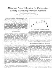
pSHIELD<strong>System</strong> <strong>Architecture</strong> <strong>Design</strong>PU3 Terms, Definitions and Approaches(1) Embedded <strong>System</strong> (ES) is a computer system designed to perform one or a few dedicatedfunctions often with real-time computing constraints. It is embedded as part of a complete deviceoften including hardware and mechanical parts. By contrast, a general-purpose computer, suchas a personal computer (PC), is designed to be flexible and to meet a wide range of end-userneeds.(2) An Embedded <strong>System</strong> is a microprocessor based system that is embedded as a subsystem, in alarger system (which may or may not be a computer system).In general, "embedded system" is not a strictly definable term, as most systems have some elements ofextensibility or programmability. For example, handheld computers share some elements with embeddedsystems such as the operating systems and microprocessors which power them, but they allow differentapplications to be loaded and peripherals to be connected. Moreover, even systems which do not exposeprogrammability as a primary feature generally need to support software updates. On a continuum from"general purpose" to "embedded", large application systems will have subcomponents at most points evenif the system as a whole is "designed to perform one or a few dedicated functions", and is thusappropriate to call "embedded".An ES is some combination of computer hardware and software, either fixed in capability orprogrammable, that is specifically designed for a particular function. Industrial machines, automobiles,medical equipment, cameras, household appliances, airplanes, vending machines and toys (as well asthe more obvious cellular phone and PDA) are among the myriad possible hosts of an embedded system.For example, the following figure shows the essential parts of an ES:• Microprocessor / DSP• Sensors• Converters (ADC and DAC)• Actuators• Memory (On-chip and Off chip)• Communication path with the interacting environmentFigure 1 - A generic embedded system structure.PUD2.3.2Issue 5 Page 14 of 122
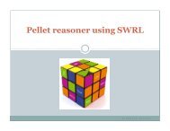
pSHIELD<strong>System</strong> <strong>Architecture</strong> <strong>Design</strong>PUEmbedded Device (ED) can be a small programmable chip that can be programmed to execute certainfunctions.Heterogeneous system is a group of interacting, interrelated, or interdependent elements forming acomplex whole.Heterogeneous device integration designates technologies that can be integrated on one platformdevice.Heterogeneous network is a network connecting computers and other devices with different operatingsystems and/or protocols.<strong>Architecture</strong>: The architecture of a system defines its basic components and important concepts anddescribes the relationships among them.Functional architecture (FA): The functional architecture can be viewed as the set of basic informationprocessing capabilities available to an information processing system. The functional architecture iscomprised of a set of primitive operations or functions. This means that these basic functions cannot beexplained by being further decomposed into less complex ("smaller") sub-functions.The functional architecture is constructed from an analysis of different functional requirements as deducedfrom different use cases.Example 1:Figure 2 shows one example of the TISPAN NGN functional architecture.a)PUD2.3.2Issue 5 Page 15 of 122
pSHIELD<strong>System</strong> <strong>Architecture</strong> <strong>Design</strong>PUb)Figure 2 – a) Overview of the functional architecture of TISPAN NGN release 2, b) layeredview of the TSPAN NGN architecture.The main scope of the above functional architecture is to identify a set of functional blocks, for example:Media Gateway Function (MGF); Border Gateway Function (BGF); Access Relay Function (ARF);Signaling Gateway Function (SGF); Media Resource Function Processor (MRFP); Layer 2 TerminationFunction (L2TF), etc. Each subsystem is specified as a set of functional entities and related interfaces. Asa result implementers may choose to combine functional entities where this makes sense in the context ofthe business models, services and capabilities being supported. Where functional entities are combinedthe interface between them is internal, hidden and un-testable.Example 2:The Web system architectures have a technical architecture that is divided in functional and informationarchitecture. For both the information architecture and the functional architecture, various abstractionlevels exist, which include the business architecture, logical architecture, physical architecture andimplementation architecture:• Business <strong>Architecture</strong>: The business architecture represents business processes, policies andprocedures, workflows and user interactions. This is used to guide the design of other moretechnical related architecture layers• Logical <strong>Architecture</strong>: The logical architecture defines at a high level the structure of the system tobe developed. The elements in this layer are logical concepts, instead of concrete or physicalsoftware componentsPUD2.3.2Issue 5 Page 16 of 122
pSHIELD<strong>System</strong> <strong>Architecture</strong> <strong>Design</strong>PU• Physical <strong>Architecture</strong>: The physical architecture further defines the technical solution at a detailedlevel. Some design decisions, such as the selection of content storage product, can berepresented in this layer• Implementation <strong>Architecture</strong>: The implementation architecture specifies system composition andinterconnectionspSHILED Functional <strong>Architecture</strong> (pSFA) is composed by four functional layers: node, network,middleware and overlay, which represent a set of four functional sub-systems that are specified by its setof elements, functional entities and interfaces.Node Layer (NoL) of pSFA: node layer is composed of Intelligent ES HW/SW Platform and havedifferent kinds of Intelligent ES Nodes: nano node, micro/personal node, power node, and DependableSelf-X Crypto Technologies. This layer is composed of standalone and/or connected NoL elements likesensors and actuators, which perform smart transmission.The NoL is a layer composed by physical nodes (i.e. hardware). Each node is a generic Embedded<strong>System</strong> (for example a sensor, an actuator, a transmitter etc.).Network Layer (NeL) of pSFA is a heterogeneous layer composed by a common set of protocols,procedures, algorithms and communication technologies that allow the communication between two ormore nodes.Middleware Layer (ML) of pSFA is the software layer that provides the basic functionalities to use theunderlying networks of embedded systems (like service discovery and composition) as well as somesecurity functionalities (like accounting or access control). This layer, being software, is installed on thenodes.Overlay Layer (OL) of pSFA is a logical vertical layer that collects (directly or indirectly) semanticinformation coming from the Node, Network and Middleware layers and uses them to compute theadequate actions (if any) that ensure the desired level of SPD. It is a software routine running atmiddleware and/or application level.3.1 Cross-Layer / Cross-Overlay <strong>Architecture</strong> Definitions3.1.1 IntroductionThe purpose of this chapter is to give an overview on the cross-layer architectures (CLAs) proposedrecently by the research community and to address in details SPD issues for overall pSHIELD <strong>System</strong><strong>Architecture</strong> (pSSA).In wireless and mobile networking envisioned for pSHIELD <strong>System</strong> <strong>Architecture</strong> (pSSA), difficultenvironmental conditions are a permanent challenge, resulting in a demand for cross-layer optimizations.There is also a need to further increase flexibility of the network. Therefore, we believe cross-layerarchitectures should adapt themselves to these changing conditions, just as they adapt the network stack,devices, and applications.The network protocol stacks are logically organized in layers. These layers are strictly separated and thecross-layer functionality between them is restricted by determined interfaces, which in effect only allowpassing packets up and down the stack. In principle, all these layers have been designed to fulfil theirfunctionality without interaction across the layers. History shows that this works well in wired and staticPUD2.3.2Issue 5 Page 17 of 122
pSHIELD<strong>System</strong> <strong>Architecture</strong> <strong>Design</strong>PUenvironments. Popularity and success of wireless networks and highly mobile nodes is currentlydominating in new development and research activities. In order to adapt to the rapidly and frequentlychanging network conditions under those circumstances, a more sophisticated interaction betweenprotocols than in a traditional layered architecture is desirable. The existing solutions are not able todynamically change which of these to use and how to use them, i.e., the adaptation, re-parameterizationand addition of cross-layer optimizations during runtime. Moreover, customization of optimizations inexisting frameworks is often cumbersome and complicated, if it can be done at all.Cross-layer architectures diverge from the existent network design approaches, where each layer of theprotocol stack operates independently and the data between the successive layers is exchanged in a verystrict and systematic manner. There are several advantages of a layered approach since modularity,robustness and ease of design are effortlessly achieved. The modularity that the layers provide allows forpotential arbitrary combination of protocols and the maintainability is being improved as new versions of aprotocol can be inserted without having to alter the rest of the network stack. However the properties ofthe different layers have substantial interdependencies and a modularized design may be suboptimal withregards to performance especially in satellite and mobile wireless environments, where thecommunication channels and traffic patterns are more unpredictable than in wired-line networks.There has been much talk about cross-layer design for wireless communication networks lately. It hasbeen argued repeatedly that layer boundaries, as specified in the layered architectures, are not suitablefor wireless communications and performance gains can be made by giving up strict layering to do crosslayerdesign [1], [2].This section discusses a communication methodology involving node cooperation which, whiledemonstrating a new opportunity created by wireless networks, significantly challenges the layeredarchitecture.Cross-layer design touches not just communications and networking, but is also intimately connected toconcepts related to communications architecture. Layered architectures have served to make the protocoldesign activity systematic and modular. Potential performance gains can always motivate a designer tonot follow the layered architectures and do cross-layer design. But cross-layer design cannot be seen asan end itself.This section presents both, a state-of-the-art (SoA) of the ongoing work and platforms over which newresearch can be built [3]-[20]. In this project we will discuss specific cross-layer design proposals and newalternatives. But mainly, we encourage a more holistic treatment of cross-layer design itself.We therefore propose a Cross-Layer pSHIELD <strong>System</strong> <strong>Architecture</strong> (CL-pSSA) with the followingproperties:• Signalling between an arbitrary amount of layers and system components• Extensibility of the architecture and adaptability of optimizations at runtime• High usability for cross-layer developers via an abstract description language for optimizationrulesThere also exist several cross-layer architectures facilitating signalling across all layers, i.e. any-to-anylayer signalling. For example, Cross-Layer Signalling Shortcuts (CLASS) enables direct signallingbetween all layers by message passing [8].PUD2.3.2Issue 5 Page 18 of 122
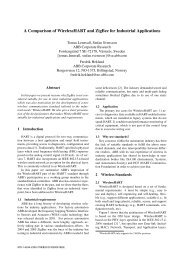
pSHIELD<strong>System</strong> <strong>Architecture</strong> <strong>Design</strong>3.1.2 Description of Cross-Layer <strong>Architecture</strong>PU3.1.2.1 A definition for Cross-Layer <strong>Design</strong> (CLD)A layered architecture, like the seven layer Open <strong>System</strong>s Interconnection (OSI) model [3], defines ahierarchy of services to be provided by the individual layers. The services at the layers are realized bydesigning protocols for the individual layers, which can be implemented on the target platform to obtain acomplete system.At the protocol design phase, the designer has two choices. Protocols can be designed by respecting therules of the original architecture. In the case of the layered OSI reference model, this would meandesigning protocols such that they only make use of the services at the lower layers and not be concernedabout the details of how the service is being provided. It also implies that the protocols would not needany interfaces that are not present in the reference architecture.Alternatively, protocols can be designed by violating the reference architecture. Since the referencearchitectures in communication and networking have traditionally been layered, its violation is generallytermed as cross-layer design.1.1.1.1 A taxonomy of CLDIn recent times, a large number of cross-layer designs have been proposed. A classification based on thelayers that are coupled by the different proposals can be found in [4]. In this section, we classify theexisting cross-layer design proposals according to the kind of architectural violations they represent. Twopoints should be mentioned here. Firstly, our coverage of the cross-layer design proposals is meant to berepresentative and not exhaustive. Secondly, the reference architecture we assume is motivated from the“best of both worlds” five-layer model proposed in [5]. Thus, we assume that the reference architecturehas the application layer, the transport layer, the network layer, the link layer which comprises the datalinkcontrol (DLC) and medium access control (MAC) sub-layers [3], and the physical layer—with all thelayers performing their generally understood functionalities.We identify the following architectural violations:1) Creation of new interfaces (Figure 3: A, B, C)2) Merging of adjacent layers (Figure 3: D)3) <strong>Design</strong> coupling without new interfaces (Figure 3: E)4) Vertical calibration across layers (Figure 3: F)A. Creation of new interfacesSeveral cross-layer designs require creation of new interfaces between the layers. These can further bedivided into three categories depending on the direction of information flow along the new interfaces:1) Upwards: From lower layer(s) to a higher layer2) Downwards: From higher layer(s) to a lower layer3) Back and forth: Iterative flow between the higher and lower layerWe now discuss the three sub-categories in more detail and point out the relevant examples.1) Upward information flow: A higher layer protocol that requires some information from the lowerlayer(s) at runtime results in the creation of a new interface from the lower layer(s) to the higherlayer, as shown in Figure 3 A2) Downward information flow: Some cross-layer design proposals rely on setting parameters onthe lower layer of the stack at run-time using a direct interface from some higher layer, asPUD2.3.2Issue 5 Page 19 of 122
pSHIELD<strong>System</strong> <strong>Architecture</strong> <strong>Design</strong>PUillustrated in Figure 3 B. Such downward flow of information is termed as Hints in [6]. As anexample, the applications can inform the link layer about their delay requirement and the linklayer can then treat packets from the delay sensitive applications with priority [7].3) Back and forth information flow: Two layers, performing different tasks, can collaborate with eachother at run-time. Often, this manifests in an iterative loop between the two layers, withinformation flowing back-and-forth between the layers, as highlighted in Figure 3 C.Figure 3 - Different kinds of cross-layer design proposals (boxes represent the protocollayers).3.1.2.2 Existing and new CLAs3.1.2.2.1 A classic CLACross-layer design proposals that we looked at in Section 3.1.2.2 demonstrate the violation of layeredarchitectures at the protocol design phase itself. Hence, a question that naturally comes up is, “Can therebe architectures that are general enough such that protocols for wireless networks can be designedwithout violating them?” In fact, this is a complicated question. Determining what the new architecturesshould look like requires the study of not only the performance issues from a communication ornetworking viewpoint, but also an understanding of the implementation related issues. Nevertheless,some preliminary proposals have been made in the literature.These can be put into two categories:1) Allowing the layers to communicate with each other (Figure 4 A)2) A shared database across the layers (Figure 4 B)A. Allowing the layers to communicatePUD2.3.2Issue 5 Page 20 of 122
pSHIELD<strong>System</strong> <strong>Architecture</strong> <strong>Design</strong>PUA straightforward way to allow information sharing between the layers is to allow them to communicatewith each other, as depicted schematically in Figure 4 A. Practically speaking this means making thevariables at one layer visible to the other layers at run-time. Notice that under strictly layeredarchitectures, every layer manages its own variables and its variables are of no concern to other layers.There are many ways in which the layers can communicate with one another. For instance, protocolheaders may be used to allow flow of information between the layers. Alternatively, the extra “inter-layer”information could be treated as internal packets. The work in [8] presents a comparative study of severalsuch proposals and goes on to present another such proposal, namely, the Cross-layer signallingshortcuts (CLASS).CLASS allows any two layers to communicate directly with one another. Similarly, the Hints andNotifications proposal discussed in [6] makes network layer the hub of inter-layer communication. Theseproposals are appealing in the case where just a few cross-layer information exchanges are to beimplemented in systems that were originally designed in conformance with the layered architectures. Inthat case, one can conceivably “punch” a few holes in the stack while still keeping it tractable. However, ingeneral, when variables and internal states from the different layers are to be shared between thedifferent layers as prescribed by such proposals, a number of implementation issues relating to managingshared memory spaces between the layers may need to be resolved.B. Shared database across the layersThe other architecture proposal recommends a common database that can be accessed by all the layers,as illustrated in Figure 4 B. See for instance references [9] and [4]. In one sense, the common database islike a new layer, providing the service of storage/retrieval of information to all the layers.The shared database approach is particularly well suited to vertical optimizations. An optimizationprogram can interface with the different layers at once through the shared database. The main issue hereis the design of the interactions between the different layers and the shared database.Figure 4 - Proposals for architectural blueprints for wireless communications.PUD2.3.2Issue 5 Page 21 of 122
pSHIELD<strong>System</strong> <strong>Architecture</strong> <strong>Design</strong>PU3.1.2.2.2 New CLA3.1.2.2.2.1 Cross-Layer Interaction ModelThe cross-layer architectures proposed in the literature do not address all the design goals ofinteroperability, rapid prototyping, maintainability, portability and efficiency. Starting from thisconsideration, the goal of this work is to provide a generic framework for building and organizing a crosslayerinteractions model (CLIM) which could serve as a unified and simple way to implement cross-layeroptimizations (see Figure 5). When using CLIM, the concept of NF (Network Feature) should also beintroduced. A NF is either a functional service that can be provided to the end-user (e.g. QoS), or anetwork component whose operations/configurations are supposed to be critical in terms of performance,efficiency or services, at the system level or for the user satisfaction. Basically, cross-layer interactionsmay be local to or distant within a network node.In many cases only two elementary NF are involved in the adaptation and interaction (one source NF, onetarget NF). In some other cases multiple (local or distant) entities could participate. Local communicationsbetween protocols of non-neighbour layers are done through a local interface that must be defined.Figure 5 - Proposed Cross-Layer Interaction ModelThe cross-layer architecture and interaction module CLIM has two main components: 1) QoS andResource Management and 2) Mobility Management. The QoS and Resource Management componentincludes:• SIP and MAC cross-layer interactions used to support the interworking between WiMAX andDVB-RCS and multimedia QoS-aware application• Transport layer and MAC cross-layer interaction (i.e. the interaction between TCP PEP(Performance Enhancing Proxy) and DAMA (Demand Assignment Multiple Access) in the MAC)PUD2.3.2Issue 5 Page 22 of 122
pSHIELD<strong>System</strong> <strong>Architecture</strong> <strong>Design</strong>PUdesigned to optimize the way in which the available resources is used taking into account QoSmapping at the MAC layer and enabling data to be sent to the lower layers at the speed at whichthe MAC layer queues are emptied (flow-control)• IP and MAC scheduling interaction implemented in a way that can fully take advantage of QoScapabilities offered by the satellite system• MAC and Physical layer interaction between DRA and DAMA as information in the frameconstitutionThe Mobility Management component utilizes a slightly modified model (CLIM-m) based on the moregeneric CLIM architecture together with ideas from [17], [18]. The mobility management modules include:• algorithms for handover prediction and decision algorithms for fast handover with handoverpreparation, handover coordination and optimization algorithms for best performance, and• information to decide the appropriate time to initiate and execute the handover procedures.The proposed cross-layer platform for mobility management specifies a Cross-layer Manager consisting ofa Link Information Manager and a Handover Manager connected to Layer Agents (LA). The HandoverManager communicates with multiple protocol layers via the LAs which capture specified parameters ineach layer when the respective values are changing beyond a certain threshold. These data are reportedto the Handover Manager to collect sufficient information for the Handover Decision Unit.3.1.2.3 ChallengesThere are additionally several open questions, some of which cannot be addressed from a performanceviewpoint alone and require a consideration of architectural concerns too. For example:• What should be the role of the physical layer in wireless networks?• Is the conventional view of the network—that of a collection of point-to-point links—appropriate forwireless networks?• How do the different cross-layer design proposals co-exist with one another?• Will a given cross-layer design idea possibly stifle innovation in the future?• What are the cross-layer designs that will have the most significant impact on networkperformance, and hence should be most closely focused on?• Has a given design proposal been made with a thorough knowledge of the effect of theinteractions between the parameters at different layers on network performance?• Under what network and environmental conditions can a particular cross-layer design proposal beinvoked?• Can the mechanisms/interfaces used to share information between the layers be standardized?• How do we make sure that the new architectures allow innovative usage of the wireless mediumthat we are likely to see in the future?We will investigate at some of these issues in greater detail.3.1.2.4 Description of LayersPUD2.3.2Issue 5 Page 23 of 122
pSHIELD<strong>System</strong> <strong>Architecture</strong> <strong>Design</strong>PU3.1.2.4.1 Physical LayerIn wired networks, the role of the physical layer has been rather small—that of sending and receivingpackets when required to do so from the higher layers. As we have seen, advances in the signalprocessing at the physical layer can allow it to play a bigger role in wireless networks. Consider, forinstance, multi-packet reception capability at the physical layer.3.1.2.4.2 MAC LayerThe MAC layer’s functionality is intimately connected to the network layer (and hence to the rest of thestack), we see that signal processing advances at the physical layer promise to have a significant impacton all aspects networking protocol design. Cross-layer designs relying on advanced signal processing atthe physical layer are an interesting research ground for the future.3.1.2.4.3 Cross-Layer PrinciplesThe solutions for cross-layer adaptation seek to enhance the performance of the system by jointlyoptimizing the performance of single or multiple cross-layers. The uncertainty is to what extent the layeredarchitecture needs to be modified in order to introduce co-operations among protocols belonging todifferent layers. At one end, solutions based on triggers between the layers implement interdependenciesbetween protocols while maintaining compatibility with strict layering. A full cross-layer design representsthe other extreme; this implies introducing stack-wide layers’ interdependencies that enable theoptimization of each protocol’s performance by exploiting the full knowledge of the network statusabstracted at different layers of the protocol stack.However, in a multiple-objective optimization scenario, care should be taken to avoid undesirable (andunpredictable) interactions across parameters in various layers, leading to conflicts or even loops betweenthe layers. There also exists a design trade-off between the multiple optimization goals and the effect ofthe increased processing and interactions to achieve these goals. Unfortunately by doing cross-layerdesign in an undisciplined way, it is likely to end with a poorly structured system and to greatly increasethe complexity of an already complex system [10][11].Figure 6 illustrates the main ideas of cross-layer adaptation and optimization in a hybrid terrestrial andsatellite network. Cross-layer optimization may be implemented locally (intra-node) or globally (internode).A number of cross-layer methods and architectures have been proposed in the literature[12][13][14] [15][16]. They all share some common features and diverge notably in the way the cross-layerprinciple is implemented, on what kind of application they focus, in the capacity the architecture has andwhere the actual adaptation intelligence is located.PUD2.3.2Issue 5 Page 24 of 122
pSHIELD<strong>System</strong> <strong>Architecture</strong> <strong>Design</strong>PUFigure 6 - Cross-layer adaptation and optimization in satellite network.These architectures mostly fit out into one of the two categories: direct or explicit cross-layercommunications and indirect or implicit cross-layer communications via a common entity, see Figure 7.PUD2.3.2Issue 5 Page 25 of 122
pSHIELD<strong>System</strong> <strong>Architecture</strong> <strong>Design</strong>PUFigure 7 - Cross-layer architectures for indirect and direct communications.The first category, direct communications, should be used when only a single cross layer optimization isplanned. The second category, indirect communications, is realized with a common cross-layer entity orcross-layer manager, which acts as a mediator between the layers. The cross-layer entity includes anetwork status component of the stack that interfaces the different layers between themselves and acts asa database where each network layer can put or get information. This architecture should be used formultiple cross layer optimizations.3.1.3 The Overlay as a Cross-Layer Security <strong>Architecture</strong> for Security, Privacy andDependabilityAs we have seen in the previous section, a Cross-Layer <strong>Architecture</strong> is a design paradigm that couldimprove the performance of a generic system by simply allowing information exchange among the layers.This approach has been widely described for Telecommunication environment, however for the purposeof the pSHIELD project we need to adapt it to a different context by addressing two main issues:i) while classical Cross-Layer is applied to the seven, well known, ISO/OSI layers, pSHIELD Cross-Layeris applied to three heterogeneous and complex layers named Node (the hardware), Network (theinterconnection between nodes) and Middleware (the software services located between the hardwareand the applications providing the core SPD functionalities)ii) while classical Cross-Layer aims at optimizing telecommunication quality of service performances (likebandwidth, transmission delays and so on), the pSHIELD Cross-Layer is in charge of addressing Security,Privacy and Dependability to bring them to a reference, desired value. With Security, Privacy andDependability we refer to a wide set of functionalities relevant for the system like Authentication,PUD2.3.2Issue 5 Page 26 of 122
pSHIELD<strong>System</strong> <strong>Architecture</strong> <strong>Design</strong>PUCryptography, Authorization, Key management, Auditing, etc. For any possible threat, pSHIELD acts as aSPD overlay, applying a functional-cross-layer approach, as depicted below:THREAT / ATTACK…INTRUSIONENERGYCOMMUNICATIONMIDDLEWARENETWORKNODEOVERLAYFigure 8 – pSHIELD Overlay.Given a threat or an attack (such as intrusion, tampering, energy shortage, communication fault, etc.) itpotentially impacts all middleware, network and node layers. To face this threats and attacks, traditionalapproaches are to defend each single functionality or each single layer, without any coordination with therest of the involved system. To ensure such an holistic approach it is necessary a Cross-Layer element toserve as a glue between the different domains (node, network and middleware). The Overlay monitorsand controls the SPD level of the whole system.In order to simplify the description, in the unfolding of the document we will refer to the “pSHIELD Cross-Layer <strong>Architecture</strong> for Security, Privacy and Dependability” with the word “Overlay Layer” or pSHIELDOverlay”.Since there are many SPD functionalities positively affected by the introduction of an Overlay layer, mostof them depending on the application scenario, it is not possible to provide in advance an extensive,quantitative description of the advantages for each SPD functionality. However in the following sectionssome examples are provided to better understand the Overlay impact on improving the SPD level of agiven system of embedded systems.3.1.3.1 SecurityThe Overlay approach could improve the security of an interconnected set of Embedded <strong>System</strong>s byleveraging the basic security functionalities of each hardware and/or software components. For example ifan encryption algorithm is required to protect the output of a node, the overlay could decide to perform itdirectly at node level (by activating the adequate chip and producing an already encrypted output) as wellas at network level (by ciphering the information while transmitting it over a secured channel) or atmiddleware level (by ciphering the information stored in memory before sending it). Of course thesesolutions are equivalent if and only if they all fit the application needs.1.1.1.2 DependabilityAn intuitive example of Dependability functionality that could be guaranteed by the pSHIELD overlay couldbe the power consumption of the system. If we consider, for example, a monitoring system composed bydifferent nodes, communication protocols and software components, the Overlay could dynamicallychoose the less expensive (in terms of energy) configuration of devices or transmission protocols andPUD2.3.2Issue 5 Page 27 of 122
pSHIELD<strong>System</strong> <strong>Architecture</strong> <strong>Design</strong>PUactive services in order to maximize the life of the battery and consequently the dependability of thesystem itself.3.2 Node Layer Definitions3.2.1 Nano and Micro/Personal NodeA pSHIELD Node is an Embedded <strong>System</strong> Device (ESD). When a Legacy ESD equipped with severallegacy node capabilities will be used in the pSHIELD network it requires a pSHIELD Node Adapter(pSNA). A pSHIELD node is deployed as a hardware/software platform, encompassing intrinsic,innovative SPD functionalities, providing proper services to the other pSHIELD networks and middlewareadapters to enable the pSHIELD composability and consequently the desired system SPD. There arethree kinds of pSHIELD node deploying each different configuration of Node Layer SPD functionalities ofthe pSHIELD framework, and comprising different types of complexity: Nano nodes, Micro/Personal(NMP) nodes and power nodes. Nano nodes are typically small ESD with limited hardware and softwareresources, such as wireless sensors. Micro/Personal nodes are richer in terms of hardware and softwareresources, network access capabilities, mobility, interfaces, sensing capabilities, etc. Power nodes offerhigh performance computing in one self-contained board offering data storage, networking, memory andmulti-processing. While the three pSHIELD Node types cover a variety of different ESDs, offering differentfunctionalities and SPD capabilities, they share the same conceptual model, enabling the pSHIELDseamless Composability.The technological advancements in computing hardware and software enables a new generation of smallESDs to perform complex computing tasks. Extremely small sensor devices provide advanced sensingand networking capabilities. In parallel, many operating systems targeting these types of devices havebeen developed to increase their performance. The method for designing pSHIELD NMP Nodes istwofold:1. To design completely new NMP nodes that are complaint with the pSHIELD system design.2. To keep legacy node technologies as they are compliant with their standards, developed formany applications including those that are targeted in pSHIELD, which means to assume aheterogeneous infrastructure of networked ESDs like IEEE 802.15.4, IEEE 802.11, etc. Anordinary sensor technology (not all, since we need those that are designed for ES) permits toconsider an augmentation of SPD functionalities at different levels of the hardware and firmwaremodules. This means an enhanced legacy NMP node with physical layer and protocol stackcomposed of existing and new SPD technologies added by pSNA. As result of this integration anew types of networked SPD ESDs will be created. pSHIELD and new SPD ESDs will composea heterogeneous SPD network infrastructure too.Developing a NMP node as integrated NMP-SPD Node of a Legacy NMP node and pSNA we obtain acomposable pSHIELD Node. It means that it has all of the desired SPD functionalities and services for thepSHIELD application scenario selected. Additionally to that, the pSHIELD Node keeps some of thedesired functionalities of a standardised sensor technology with additional SPD features that make itcomposable into the pSHIELD framework. The architectural design of the pSHIELD Nodes will relay onthe ISO/IEC 9126 standard that has 6 top level characteristics:• functionality,• reliability,• usability,PUD2.3.2Issue 5 Page 28 of 122
pSHIELD<strong>System</strong> <strong>Architecture</strong> <strong>Design</strong>PU• efficiency,• maintainability and• portability.The architectural design of the NMP nodes is not an easy architectural task since it requires consideringmany different constraints at the same times. Some of these constraints can converge in the samedirection but some of them will be divergent and in the opposite directions. To cope with this challengearchitectural design, as shown in section 4, the pSHIELD ESD use two approaches:- network approach and- functional approach.The network approach constrained the architectural system design from network point of view. Thisapproach should guarantee that all NMP nodes are part of a pSHIELD-SPD network that can be easilyintegrated with standard IP-based network like GSM, UMTS, etc. In other words it means that an SPDnetwork is implementable and interoperable with standard networks to comply the main business cases ofthe application scenarios.The functional approach constrained architectural design from the SPD requirements point of view and itis related to the node, network, middleware and overlay layers. The real innovation of pSHIELD is theintroduction of the Overlay that makes the two approaches converge.Nano- and micro- sensor technology encompasses the family of devices in the dimension scales ofnanometers and micrometers respectively. They are simple machines with limited capabilities andresources that include sensing, simple computations, small memory and data transmission in shortdistances. Biological sensors, inside the human body and sensors integrated in things, such as books orkeys are two example types of nano- and micro- sensing. The rise of these two technologies (andcombinational schemes of them) is expected to have great impact in many aspects of social life, such ashomeland security or environmental protection.Nano- and micro- sensor technology encompasses the family of devices in the dimension scales ofnanometers and micrometers respectively. They are simple machines with limited capabilities andresources that include sensing, simple computations, small memory and data transmission in shortdistances. Biological sensors, inside the human body and sensors integrated in things, such as books orkeys are two example types of nano- and micro- sensing. The rise of these two technologies (andcombinational schemes of them) is expected to have great impact in many aspects of social life, such ashomeland security or environmental protection.Such devices are often integrated in larger units to form nano- or micro-machines dedicated to sensing oractuation functionalities. Interconnections of these machines create networks able to serve applications inlarger areas, expanding the degree of range and complexity. Further, these networks can communicatewith other networks or connect on Internet based applications to make the distribution of information evenmore widespread.Nano-engineering is one of the new eras of technological challenge and the research is on going. In thiscontext, the communication techniques of these networks are still immaturely standardized. It is usuallynot crystal clear how these small devices communicate. Furthermore, a lot depend on the topology, thecomponents and network architecture of the specific application. It is self-evident that the development ofPUD2.3.2Issue 5 Page 29 of 122
pSHIELD<strong>System</strong> <strong>Architecture</strong> <strong>Design</strong>PUnanonetworks implies the arrangement of a wide set of parameters (just like every communicationnetwork), including:• Architectural framework (sensors, routers, gateways)• Frequency band of operation• Channel modelling (path-loss, noise, bandwidth and capacity)• Modulation• Protocols (MAC addressing, routing, service discovery)Therefore, a brief technical summary of the pSHIELD nano- and micro- platform is considered useful, incontrast to further theoretical definitions.The pilot demonstrator of pSHIELD uses the Sun SPOT sensor platform as micro node. Sun SPOT is auseful platform for developing and prototyping application for sensor network and embedded system. SunSPOT is suitable for application areas such as robotics, surveillance and tracking.3.2.1.1 Technology DescriptionThe SPD goal for the NMPS node prototypes is to take in consideration the following design constrains:I. For RT scenario, which belongs also to critical infrastructure (CI), high security of WSNscomposed of secured NMPS nodes is compulsory.II. NMPS nodes are energy and resources-constrained.III. Secure ES firmware, secure boot, secure upgrade mechanisms, and TCG technologies areneeded for enhancing security.Development platform should have two separate prototypes:1. NMPS node platform2. TPM platformThe choice of the processor and memory performance is very important since the program memory sizeddefies performance (MIPS) and computational time (ms). Selection of all other components for bothplatforms is constrained with constrains I, II and III.3.2.1.2 NMPS node prototypeBefore we decided which type of tiny sensor node will well suited with the pSHIELD requirements weinvestigated many suitable solutions. Fig illustrates the most recent sensor platforms that can be used forNMPS node (generic sensing type or gateway). For video applications the current sensor node platformsare showing lack of processing power and memory sizes. Therefore, low-resolution image sensors areconsidered for NMPS node. Additional goals for the NMPS node are:• The node should have the memory-performance size 100-1000 KB and 10-100 MIPS.• WSNs will multi-tier type. For example Tier “0” is has nano nodes, tier “1” micro/personal nodes,and tier “2” more powerful micro/personal nodes as gateways, and tier “3” has power nodes.• The NMPS nodes should be able to connect: low-resolution camera, passive infrared (PIR),acoustic/ultrasound, temperature, pressure, humidity, etc.PUD2.3.2Issue 5 Page 30 of 122
pSHIELD<strong>System</strong> <strong>Architecture</strong> <strong>Design</strong>• It should have sufficient low power consumption when is used with a battery.• It should allow a wide range of applications.• USB interface for programming the applications and data retrieval.PU• Separate USB interface will be for radio module.• To connect the image sensor and other sensors an expansion connector is used.3.2.1.2.1 Microcontroller/Microprocessor comparisonFirst of all, choose of a microcontroller unit (MCU) based on several requirements such as low powerconsumption, rich on-chip peripherals, RAM and ROM, etc. Table below shows the comparison of theMCUs.MCU RAM (kB) FLASH (kB) Active (mA) Sleep (μA) Sensor NodesAtmega128(Atmel)4 128 8 20 DSY25, EberNet,BT node, Iris,MicaZ, Mica2AT91SAM7128 32 128 30 10 Evaluated(Atmel)Atmega644/V4 64 0.4 0.1 TelG Mote(Atmel)STM32W108B*STMicroelectronics8 128 6@12MHz
pSHIELD<strong>System</strong> <strong>Architecture</strong> <strong>Design</strong>3.2.1.2.2 IEEE 802.15.4 chips comparisonPUFor WSNs the selection of the radio is a critical for NMPS nodes, because the performance should not beevaluated for a individual NMPS node. The application requirements define what type of radio is needed.A wideband radio operating at 2.4 GHz and comply with IEEE 802.15.4 standard offer advantages thatare important for the pSHIELD scenario. There are several radio modules available in the markets that arein compliant with IEEE802.15.4 standard. Most of the module differences lie on its power profile, deviceinterface and additional features. Several IEEE802.15.4 compliant radio from Atmel, Chipcon, Microchipand MaxStream are listed Table below. When very high data rate are required (depends of the applicationrequirement) AT86RF231 is the best choice. XBEE module from MaxStream has 50 mW output powerand range from 40 m - 1.6 km. The module also provides a complete solution including the antenna.Other radio chip requires a careful design of an external antenna. The USART device interface is veryeasy to configure and XBEE has two modes of operation which are transparent and API mode.AtmelAT86RF231ChipconCC2420MicrochipMRF24J0MAMaxStreamXBEEData rate (kbit/s) 250, 500,250 250 2501000, 2000Rx power (mA) 12.3 19.7 19 50Tx power14/+3 17.4/0 23/0 45(mA/dBm)Power down (µA) 0.02 1 2
pSHIELD<strong>System</strong> <strong>Architecture</strong> <strong>Design</strong>PUthe direction up and downwith the value either ±2G or ±6G. When the Sunspot is at rest, itmeasures x = y = 0 and z = 1G• Light sensor isof the type TPS851, designed by Toshiba. The sensor can measure the voltagebetween 0.1V (dark) - 4.3V (light), and converts the voltage to the brightness ofLuminance (lx) 3Software components: SUN SPOT JVMSquawk isopen sourceand has been written in the Java programming language. It is a virtual machine,and is a highly portableJava VM. The advantageof Squawk is that it can run on bare metal instead ofbeing run on top of theoperating system. This means that applications canbe isolated and be treated asapplication objects. This allows multiple applications running on the same virtual machine. Squawk alsosupports CLDC 1.1 that facilitates connectivity tomobile phones.3.2.2 Power NodeThe Power Node is a rugged embedded system, providing high computing power, optimally designed interms of dimensions, weight, powerconsumptionn and capable to work in harsh environmental conditions.The reference application contextt is defence/ /aerospace ground mobile and airborne environments,addressing manned and unmanned applications where reliable high performance computing is required.The Power Node is a pSHIELD SPD Embedded <strong>System</strong> Device. It is a physical component that offersnative SPD features at different abstraction levels: hardware, firmware, network and operating system.The native support ofSPD features and the high level of standard adopted, in terms of hardwarearchitecture and operating system, make it readyto host middleware and overlay services.The node offers low level native SPD capabilities, which are available as hardware components, hardwareinterfaces, firmware functionalities and network functionalities.Figure 9 – Power Node pSHIELD component.The node hardware capabilities arefocused on security, dependability andcomposability. These featuresare provided by the architecture of the node, by the hardwarecomponentsavailable onit, by its hardwareinterfaces, by the firmware and by the compliance with MIL standards. Thefeatures include:PUD2.3.2Issue 5Page 33 of 122
pSHIELD<strong>System</strong> <strong>Architecture</strong> <strong>Design</strong>PU• components which can be reconfigured (i.e. FPGA) and interfaces that allows reconfiguration atsystem level (redundant power supply, node redundancy, spare node, etc.)• set of FPGA SPD core blocks• firmware that supports remote reconfiguration of BIOS, FPGA images, etc.• power supply monitoring and protection unit• monitoring devices that allow to control continuously the status of the node• programmable I/O and network interface• BMC embedded unit• MIL standard to ensure that the node is capable to work in critical environmental conditionsThe node hardware functionalities intend to support security, privacy and dependability. Thesefunctionalities are based on the capabilities and features offered by the hardware available on the PowerNode board. The functionalities include:• reconfigurablity functionalities for components, interfaces and firmware• functionalities for security monitoring (through a dedicated FPGA core logic)• cryptographic functionalities (through a dedicated core of the FPGA or using Intel AES-NItechnology)• functionalities to monitor continuously working parameters, performance and status of node• composability functionalities that allow to implement networks of Power Nodes, increasing faulttolerance, computing power, security and dependabilityThe network services are oriented to increase privacy and dependability. These services are intendedmainly to provide some Power Node hardware functionalities remotely. The network services include:• services for remote reconfiguration of BIOS and FPGA• SNMP services• services for remote self-test and performance monitoring• privacy and login management servicesThe node SPD services rely on the hardware capabilities and functionalities, on the network services andon the operating system, offering a set of more abstract services that can be used by the middleware andoverlay layers. The set of services includes:• FPGA and BIOS reconfiguration services• privacy and user control services• composability services• status and performance monitoring services;• services for the management of the topology of Power Nodes NetworkThe Power Node has been conceived to host entire parts of the pSHIELD middleware and of thepSHIELD overlay, in particular when the requirements in terms of computing power, hardwarecomposability and reliability are important. In this context, it acts as a computing and reasoning node,more than a data acquisition node. The middleware and overlay services that can be hosted depend onthe application context and the role of the parts themselves. From an operating system and applicationpoint of view the Power Node can be seen as a very powerful rugged personal computer therefore, anypart of the pSHIELD middleware and overlay that runs on a PC may run also on the Power Node.PUD2.3.2Issue 5 Page 34 of 122
pSHIELD<strong>System</strong> <strong>Architecture</strong> <strong>Design</strong>PU3.2.3 Cryptography TechnologiesThis section presents in a summarized way the most relevant cryptography technologies related termsand definitions used in pSHIELD project. It is divided in the following sections: attacks on cryptosystems,attacks on protocols, asymmetric and symmetric cryptography, message authentication codes and keymanagement.Elliptic curve cryptography (ECC) is becoming a powerful cryptographic scheme. Because of its efficiencyand security is a good alternative to cryptosystems, like RSA and DSA, not just in constrained devices,but also on powerful computers. ECC is very important in the field of low-resource devices such as smartcards and Radio Frequency Identification (RFID) devices because of the significant improvements interms of speed and memory compared to traditional cryptographic primitives (e.g. RSA). Memory is one ofthe most expensive resources in the design of embedded systems which encourages the use of ECC onsuch platforms. Security, implementation and performance of ECC applications on various mobile deviceshave been examined and it can be concluded that ECC is the most suitable PKC scheme for use in aconstrained environment.More and more electronic transactions for mobile devices are implemented on Internet or wirelessnetworks. In electronic transactions, remote client authentication in insecure channel is an importantissue. For example, when one client wants to login a remote server and access its services, such as onlineshopping and pay-TV, both the client and the server must authenticate the identity with each other forthe fair transaction.The remote client authentication can be implemented by the traditional public-key cryptography. Thecomputation ability and battery capacity of mobile devices are limited, so traditional PKC, in which thecomputation of modular exponentiation is needed, cannot be used in mobile devices. Elliptic curvecryptosystem (ECC), compared with other public-key cryptography, has significant advantages likesmaller key sizes, faster computations. Thus, ECC-based authentication protocols are more suitable formobile devices than other cryptosystem. However, like other public-key cryptography, ECC also needs apublic key infrastructure (PKI) to maintain the certificates for users’ public keys. When the number ofusers is increased, PKI needs a large storage space to store users’ public keys and certificates. Inaddition, users need additional computations to verify the other’s certificate in these protocols.A WSN is a wireless ad-hoc network consisting of resource-constrained sensoring devices (limited energysource, low communication bandwidth, small computational power) and one or more base stations. Thebase stations are more powerful and collect the data gathered by the sensor nodes so it can be analyzed.Routing is accomplished by the nodes themselves as any ad hoc network through hop-by-hop forwardingof data. Common WSN applications range from battlefield exploration and emergency rescue operationsto surveillance and environmental protection.Security and cryptography on WSNs meet several open problems even though several years of intenseresearch. Given the limited computational power and the resource-constrained nature of sensoringdevices, the deployment of cryptography in sensor networks is a difficult task. In D3.2 is presented theimplementations of elliptic curve cryptography in the tiny sensor nodes. <strong>Design</strong> goals for a sensor platformis to develop optimizations specifically:(i)(ii)(iii)the cost of memory addressing;the cost of memory instructions;the limited flexibility of bitwise shift instructions.D3.2 work presents efficient implementations for arithmetic of binary field algorithms such as squaring,multiplication, modular reduction and inversion at two different security levels. These implementationstake into account the characteristics of the target platform. The implementation of field multiplication andPUD2.3.2Issue 5 Page 35 of 122
pSHIELD<strong>System</strong> <strong>Architecture</strong> <strong>Design</strong>PUmodular reduction algorithms focuses on the reduction of memory accesses and appears as the fastestresult for this platform.3.2.3.1 Attacks on CryptosystemsThere are a number of techniques that have been used in the past to exploit weaknesses of somecryptographic algorithms and are currently used as basic evaluation criteria for new algorithms. Thecommon aim of these attacks is to reveal partially or entirely the information encrypted in interceptedmessages, or to extract some information internal to the encryption process (without initially knowing anysecrets). They include:• Brute force attack - traversing the entire encryption key space in order to learn the encryption key• Dictionary attack - related to the brute force attack in that a set of keywords are used as possiblevalues of the encryption key (or a pass phrase)• Chosen cipher text attack - obtaining information about a secret decryption key by submitting arange of cipher texts to decrypt• Adaptive chosen cipher text attack - a version of chosen cipher text attack in which the attackerinteractively selects subsequent cipher texts based on the results of decryption of the previousones• Cipher text-only attack - the attacker has access to a limited set of cipher texts• Known plain text attack - the attacker has access to a number of cipher texts together with thecorresponding plain texts• Chosen plain text attack - the attacker can encrypt an arbitrary set of chosen plain texts• Adaptive chosen plain text attack - like above, but the attacker chooses subsequent plain text forencryption based on the previous results• Related-key attack - the attacker has access to encryption of a plain text under several differentkeys whose exact values may not be known but which are somehow mathematically relatedIn addition to these general attack methods, there is also a range of more general cryptanalytictechniques that may be used to study the properties of ciphers. They include frequency analysis,differential cryptanalysis, linear cryptanalysis, statistical cryptanalysis and mod-n cryptanalysis. Finally,there are also attacks on hashing functions (e.g., birthday attack) that aim at finding collisions in hashfunctions or attacks on random number generators that exploit a generator’s statistical weaknesses tosimplify breaking a cipher that uses it.3.2.3.2 Attacks on ProtocolsCommunication and security protocols can be attacked in a number of ways by intercepting and insertingmessages in the communication channel. These attacks are even easier to perform in wireless networkssince there might be little difficulty in accessing the channel, unless a more sophisticated technology suchas direct-sequence spread spectrum (DSSS) or frequency hopping is used.• Replay attack - resending of some captured messages in order to confuse the protocol or toexploit some of its weaknesses• Wormhole attack - a form of a replay attack that uses a low-latency and long-range transmissionlink to intercept communications in one part of the network and then to reproduce them in anothernetwork region, for example, with the goal of authenticating the attacker• Man-in-the-middle attack - the attacker intercepts all communications from a node A, modifiesthem and sends to a node B in such a way that both A and B have the illusion of directcommunication with each otherPUD2.3.2Issue 5 Page 36 of 122
pSHIELD<strong>System</strong> <strong>Architecture</strong> <strong>Design</strong>PU• Bit flipping attack - selectively flipping bits in intercepted messages in order to achieve desiredprotocol behaviour, for example, to route traffic to different recipients or to change the messagetype• Attack on key distribution protocols - preventing or intercepting key distribution in the networkmight severely affect the entire safety infrastructure of the system• Routing protocol attacks - the attacker may influence the contents of routing tables of somenetwork nodes or even to introduce corrupt nodes to affect communication in the network3.2.3.3 Asymmetric CryptographyAsymmetric cryptography, also known as public key cryptography, is based on the disposition of two typesof keys, a public key and a private key, that are used in the cryptographic operations. Intuitively, the publickey is made available by a given entity to potential senders while the private key is kept hidden by thatentity. A message sent to an X receiver should be encrypted by X’s public key where X can later decrypt itusing its private key.There are mainly three well-known types of asymmetric cryptography algorithms (Eisenbarth & Kumar,2007): Elliptic Curve Cryptography (ECC), Rivest Shamir Adleman (RSA) and EL-Gamal. Depending onthe target application and scenario specifications, implementations of the aforementioned approaches canbe in software, hardware or a co-design of both.3.2.3.4 Symmetric CryptographySymmetric ciphers use the same key or a pair of trivially-related keys (e.g., one is a linear transformationof the other) for both encryption and decryption of messages. Historically, symmetric ciphers precede theirasymmetric counterparts and although less versatile in their applications, they continue to be widely useddue to the fact that they are typically several orders of magnitude faster, as well as, they can beimplemented more efficiently. The main downside of symmetric key cryptography is the need to establisha secure communication channel for key exchange between the communicating parties before the actualcommunications can begin. As a result, asymmetric (public key) cryptography is often used to exchangesymmetric session keys between the two parties and then to use a symmetric cipher to encrypt allsubsequent communications.Symmetric ciphers can be grouped into two broad categories: stream ciphers and block ciphers. Theformer combine a pseudo-random bit sequence with the plaintext (typically an XOR) and, thus, operate onindividual bits or bytes of the plaintext, while the latter use fixed-size blocks of plaintext. Stream ciphersare typically faster and simpler to implement than block ciphers, both in software and in hardware, and arebetter suited for encryption of transmissions of streams of large amounts of data (e.g., video streams).However, stream ciphers have been reported to have serious security vulnerabilities when not usedcarefully. In particular, keys should never be reused otherwise the plaintext can be easily recovered.Block ciphers use fixed-size blocks of plaintext, typically of 128 bits and transform them in a sequence ofoperations, called rounds. Encryption of messages longer than the block size is done using a mode ofoperation, i.e. a technique of partitioning the plaintext into a sequence of blocks and then chaining theirencryption to construct the cipher text of the entire message. Encryption of plaintexts smaller than theblock size is done using a padding scheme.3.2.3.5 Message Authentication CodesThe ability to create a unique and non-forgeable digest of a message is of great practical importance. Inparticular, message authentication can be implemented by directly linking the sender's identity to themessage's contents in form of a message authentication code (MAC). There are two general ways ofimplementing MACs: using cryptographic hash functions and running block ciphers running special modessuch as, for example, cipher block chaining (CBC).PUD2.3.2Issue 5 Page 37 of 122
pSHIELD<strong>System</strong> <strong>Architecture</strong> <strong>Design</strong>PU3.2.3.6 Key ManagementA key management scheme is an integral part of any deployed security system. Whether thecryptographic approach followed is symmetric or asymmetric, the role of an efficient key managementscheme is vital. Such a scheme is affected by the system's architecture, device classes, deploymentenvironment, potential attacks and other factors. For example, a key management scheme for a secureWSN needs to deal with the limitations of such a system in terms of nodes computational, storage andenergy constraints in addition to expensive wireless communication. Essentially, key managementcomprises key pre-distribution approaches and other schemes dependent on the nature of the network. Inall cases, certain basic operations should be supported such as key addition, revocation and renewal.3.3 Network Layer Definitions3.3.1 General Network Layer descriptionNetwork Layer is responsible for delivering data packets of variable length between hosts belonging todifferent networks. Implementation depends on application environment and possible collaborativenetworks. Generally, it may include connectionless communication, hosts addressing and messageforwarding, with IP and IP-based protocols being the most popular technology patterns. Network Layerdesign goes in accordance with MAC specification and may involve topics, such as, selection of theInternet Protocol Suite, Mobile IP for IPv4/IPv6 and Security Management, where IPsec is an openstandard security scheme for authentication and encryption of IP packets.The pSHIELD Network Layer is charged with routing, multi-fold connectivity tasks and trusted datatransfer among system components. Representative (for the scope of pSHIELD) topology of participatingnodes and their homogeneous or not “islands”, form the network’s structure. The offered communicationcapabilities and overall network functions are presented. The interactions and communication with otherlayers and modules should be described through well defined interfaces. A conceptual and modularNetwork Layer architecture is designed through a methodology that encompasses all the critical featuresdescribed already as the focus of the current study. Network Layer multi-technology architectural design isbased on a series of “key” factors, adjusted in the view of pSHIELD networking needs. The mostprominent of these factors (to be taken under consideration) are the following:• 6 key concepts of pSHIELD• Network requirements, phrased in deliverable D2.1• Selection of Nodes• Security, Privacy and Dependability functions and features• Application Scenario• Software stack• Reference <strong>Architecture</strong>• Connectivity and Trusted Routing• Technology status• Metrics• Interactions and Interfaces, Cross Layer <strong>Architecture</strong>PUD2.3.2Issue 5 Page 38 of 122
pSHIELD<strong>System</strong> <strong>Architecture</strong> <strong>Design</strong>• Robustness and Composability in the general system framework• Commitment to the Technical AnnexPUCryptographic nodes(IEEE 802.15.4 channel 11)`Nano nodes(IEEE 802.15.4 channel 13)Service DiscoveryAgent / UPnPBridgeService DiscoveryAgent / UPnPBridgeLANInternetMicro/Personal nodes(IEEE 802.15.4 channel 15)Self-x nodes(IEEE 802.15.4 channel 17)FPGAPower node(IEEE 802.15.4 channel 19)3.3.2 Software Defined RadioFigure 10 - Network Layer: paradigm architecture.SDR platform will be used to provide smart SPD driven transmission. It is a radio communication softwaresystem, implemented on software (e.g., on embedded devices), meant to replace system components,such as amplifiers, filters, mixers, modulators, originally implemented in hardware. It can receive andtransmit a variety of different radio waveforms, based on the software used. It can, also, be integratedeasily with hardware security modules. Significant advantages can be derived from this alternativerealization of a radio communication system:• Variable network parameters can be set straightforwardly and on-line, whereas in hardwareimplementation reconfigurations are, frequently, cumbersome or need to be conducted manually• The communication itself can be changed, providing the possibility of access to different networks(e.g., GSM and Wi-Fi) without having to switch between different devices• Signal processing can be managed by a general purpose processor, providing a radio that canreceive and transmit heterogeneous waveforms (depending on the specific software used)• SDR is flexible in overcoming problems of limited spectrum availability• Addition of an SDR node in a mesh network increases its capacity and reduces energy consumedper nodeSmart transmission techniques by pSHIELD Network Layer will rely on waveform-agile implementations ofSDR. The two basic elements which model an SDR system are a computing unit and an RF front end. InPUD2.3.2Issue 5 Page 39 of 122
pSHIELD<strong>System</strong> <strong>Architecture</strong> <strong>Design</strong>pSHIELD <strong>Architecture</strong>, SDR in cooperation with Cognitive Radio (CR), will be used to derive from SPDmodules the corresponding desired communication and security functionalities.3.3.3 Cognitive RadioPUCognitive Radio is a radio communication standard, able to change its transmission and receptionparameters, according to conclusions deduced from sensing the frequency spectrum. The objective is todetect the unused spectrum and utilize it to set up radio communication. CR scouts the environment andadapts to user needs, without neither involving the user in this procedure, nor interfering with the hostnetwork, while conforming to FCC rules. As its inspirator Joseph Mitola III described, the motive behindCR is to render users aware of available radio resources, in order to serve their communication needs,without obstructing these resources’ allocation and normal function of the whole network. CR is itself anetwork node performing (concisely) the following actions, in the procedure of setting successfully a radiocommunication:• Detection of free frequency spectrum• Creation of a channel to use this spectrum• Function without interfering with native devicesAnd more analytically, the main functions and methods of CRs could include:• Spectrum SensingTransmitter detection: CR detect signals from specific transmitters in specific spectrumCooperative detection: information from multiple CRs is used for detectionInterference based detection• Spectrum Management• Spectrum Mobility Spectrum Analysis Spectrum Decision Spectrum Pooling: allocation of resources between users Spectrum Leasing Spectrum Sharing: a stack of spectrum is given to users (similar to MAC channeladdressing) Negotiated Spectrum Use Opportunistic Spectrum Use Dynamic Spectrum Access A CR user exchanges its operation frequencyAlthough primary observations concern frequency spectrum usage, other factors can be inspected also,such as user behaviour, channel conditions, network state and link performance. Subsequently the CRmay decide to alter communication settings, from which the most usual are waveform, protocol, frequencyand power, to meet the required level of QoS.PUD2.3.2Issue 5 Page 40 of 122
pSHIELD<strong>System</strong> <strong>Architecture</strong> <strong>Design</strong>PUCR uses unlicensed frequency bands or alternatively, fairly used licensed ones. Its success led FCC toconsider open further bands for unlicensed use. IEEE 802.22 is a standard for CR air interface(PHY/MAC), belonging to WRAN communication protocols. It is developed for Cognitive Radiotechniques, to exploit geographically unused spectrum. Additionally, IEEE P1900 is a standard committeeand group focusing on the development of standards dealing with spectrum management.Having a brief view on the architectural schemes of SDR/CR, we can add to prerequisite blocks (apartfrom the radio front end and the computer system we saw in previous paragraph) a control unit, capableof making decisions following spectrum sensing and concerning methods of spectrum management.Variability of options appears in the computing unit selection:a) General purpose processorb) Application specific processors and integrated circuitsc) FPGAs for reconfigurable computingd) Embedded <strong>System</strong>sThe last category shows that Embedded <strong>System</strong>s and SDR/CR architectures fit quite well and direct us topSHIELD Network Layer application techniques. Reversely, speed of ESs, together with low energyrequirements, rather small programming effort and the specific nature of tasks they perform makeSDR/CR schemes a suitable communication model. Also, due to the nature of ESs’ Operating <strong>System</strong>s,SDR/CR devices can have, comfortably, quick reset and reconfigurability processing times, without thedemand of lengthy off-line periods. The cost of the combination SRD/CR with ESs could be veryreasonable, allowing us to seamlessly improve network performance in application domains. CognitiveRadio, for example, is an emerging radio approach in emergency communications, to face issues of vitalimportance, such as the usual network congestion during the peak of a crisis or difficulties inintercommunication between authorities resulting from heterogeneous communication protocols andsystems.In chapter 6, <strong>System</strong> <strong>Design</strong>, SPD Driven Transmission and Trusted Connectivity are examined further,as functions of pSHIELD Network Layer, provided by the appliance of SDR/CR architecture.3.4 Middleware Layer DefinitionsThe Middleware layer is seen, from a pSHIELD perspective, as a pure software-based layer playing a keyrole to interface the Node and Network layer to the Overlay layer. The Middleware layer is shown in thebelow figure highlighted in grey.PUD2.3.2Issue 5 Page 41 of 122
pSHIELD<strong>System</strong> <strong>Architecture</strong> <strong>Design</strong>PUApplication ScenariopSHIELD Middleware LayerLegacy MiddlewareCapabilitiespSHIELD Middleware AdapterCore SPD ServicesandInnovative SPD FunctionalitiesSensed MetadataElaborated MetadataRules for discoveryand compositionSemanticKnowledgeRepositoryControl algorithmsHeterogeneous SPD‐relevantparameters and measurementsSPD Security AgentCommands for composition andconfiguration of SPD modulesExchangedmetadatapSHIELD Node LayerpSHIELD Node AdapterInnovative SPDFunctionalitiespSHIELD Network LayerpSHIELD Network AdapterInnovative SPDFunctionalitiesOther SPD SecurityAgentsLegacy NodeCapabilitiesLegacy NetworkCapabilitiespSHIELD OverlayLayerFigure 11 – pSHIELD Middleware layer.Given an application scenario, the pSHIELD Middleware layer is in charge to get heterogeneous SPDrelevantparameters and measurements from the Node and Network layer adapters. This information,jointly with the ones gathered from the Middleware layer, are semantically enriched and sent to theOverlay layer as sensed metadata. Once the Overlay layer elaborates these information as inputs ofproper control algorithms, it sends back to the Middleware layer the best rules to discover and composethe available SPD middleware, network and node resources. Indeed the discovery and compositionservices are part of the Core SPD Services provided by the pSHIELD Middleware layer. The Core SPDServices are detailed in the following section. Once activated, the Core SPD Services elaborate theproper commands and configuration to compose the available legacy Middleware, Network and Nodelayer capabilities as well as their innovative SPD functionalities.Given an application scenario, it is possible to identify a legacy Middleware layer (e.g., CORBA, DCOM,etc.), composed by several Legacy Middleware Capabilities (e.g., remote procedure call, messagingqueues, etc.). To be pSHIELD compliant, a Middleware layer must have a pSHIELD Middleware adapter,providing a mandatory set of Core SPD Services (i.e., discovery, composition, orchestration) and anoptional set of innovative SPD functionalities (e.g., identification, authentication, auditing, accounting, antitampering,etc.).3.4.1 SPD Driven SemanticsIn order to cope with the intrinsic Embedded <strong>System</strong>s complexity and heterogeneity the proposed solutionis to design and implement a proper abstract, comprehensive semantic model able to provide ahomogeneous representation of heterogeneous SPD-related parameters and conceptual models. So thePUD2.3.2Issue 5 Page 42 of 122
pSHIELD<strong>System</strong> <strong>Architecture</strong> <strong>Design</strong>PUidea is to abstract from Embedded <strong>System</strong>s peculiarities and focus only on their abstract SPD semantic.In other words, the aim is to allow that heterogeneous SPD functionalities are seen by the Overlay as ifthey were a Seamless homogeneous pool.To this purpose the technology-dependent SPD functionalities are abstracted in order to achieve atechnological-independent framework; this task will be performed by extensively using semantic modellingtechniques. As a consequence a uniform semantically-enriched ontological representation of carefullyselected SPD functionalities can be achieved, which is fundamental in order to flexibly handle and controlthe considered Embedded <strong>System</strong>.Semantic models in pSHIELD lean on the concept of ontology and ultimately shall enable interoperabilityat different levels in the conceptual framework of pSHIELD.Given that the SPD domain in Embedded <strong>System</strong>s shall be captured by a number of ontology, automaticreasoning is enabled in order to support several features of the pSHIELD framework.Broadly speaking, a semantic engine (reasoner) shall enable interoperability within Middleware Layer andrule based discovery and composition within Overlay Agents, in such a way to provide the followingessential enabling mechanisms:• Semantic reasoning based on ontology models may carry out a reconciliation of heterogeneousformats of parameters exchanged between different layers (also suitable for interaction withlegacy agents)• The semantic characterization of the behavioural aspect of components makes it suitable for anagent to determine “what the service does”The semantic characterization of the composition of functionalities and of the relations among themmakes it suitable for an agent to reason about SPD metrics of the current configuration and – if needed -to carry out reconfigurations of the system at run-time, by means of rule-based combination / compositionof components and SPD technologies, in order to achieve the new intended values for SPD metrics.3.4.2 Core SPD ServicesThe Core SPD Services are a set of mandatory basic SPD functionalities provided by a pSHIELDMiddleware Adapter with the aim to mediate the information exchange between the Overlay vertical layerand the three horizontal layers.In particular, the Core SPD Services are in charge of:• discovering and keeping updated the available SPD resources, services, functionalities, data andcontextual information coming from the Node, Network and Middleware layer• translating technology-dependent heterogeneous information into technology-independentmetadata• filtering, semantically enriching and aggregating mentioned metadata which will be eventuallystored in the Semantic Knowledge Representation database of the pSHIELD Overlay• enforcing the Overlay decisions all over the three horizontal layers, i.e. from the Middleware layerdown to the Node layer, passing through the Network layerThe core SPD services are a set of mandatory basic SPD functionalities provided by a pSHIELDMiddleware Adapter in terms of pSHIELD enabling middleware services. The core SPD services aim toprovide an SPD middleware environment to actuate the decisions taken by the pSHIELD Overlay and tomonitor the Node, Network and Middleware SPD functionalities of the Embedded <strong>System</strong> Devices underthe pSHIELD Middleware Adapter control. The following core SPD services are provided:PUD2.3.2Issue 5 Page 43 of 122
pSHIELD<strong>System</strong> <strong>Architecture</strong> <strong>Design</strong>PU• secure service discovery• service composition• service orchestrationSecure service discovery allows any pSHIELD Middleware Adapter to discover in a secure manner theavailable SPD functionalities and services over heterogeneous environment, networks and technologiesthat are achievable by the pSHIELD Embedded <strong>System</strong> Device (pS-ESD) where it is running. Indeed thepSHIELD secure service discovery uses a variety of discovery protocols (such as SLP 1 , SSDP 2 , NDP 3 ,DNS 4 , SDP 5 , UDDI 6 ) to harvest over the interconnected Embedded <strong>System</strong> Devices (ESDs) all theavailable SPD services, functionalities, resources and information that can be composed to improve theSPD level of the whole system. In order to properly work, a discovery process must tackle also a secureand dependable service registration, service description and service filtering. The service registrationconsists in advertising in a secure and trusted manner the available SPD services. The advertisement ofeach service is represented by its formal description and it is known in literature as service description.The registered services are discovered whenever their description matches with the query associated tothe discovery process, the matching process is also known in literature as service filtering. On the light ofthe above an SPD services discovery framework is needed as a core SPD functionality of a pSHIELDMiddleware Adapter. Once the available SPD services have been discovered, they must be prepared tobe executed, assuring that the dependencies and all the services preconditions are validated. In order tomanage this phase, a service composition process is needed.Service composition is in charge to select those atomic SPD services that, once composed, provide acomplex and integrated SPD functionality that is essential to guarantee the required SPD level. Theservice composition is a pSHIELD Middleware Adapter functionality that cooperates with the pSHIELDOverlay in order to apply the configuration strategy decided by the Control Algorithms residing in thepSHIELD Security Agent. While the Overlay works on a technology independent fashion composing thebest configuration of aggregated SPD functionalities, the service composition takes into account moretechnology dependent SPD functionalities at Node, Network and Middleware layers. If the Overlaydecides that a specific SPD configuration of the SPD services must be executed, on the basis of theservices’ description, capabilities and requirements, the service composition process ensures that all thedependencies, configuration and pre-conditions associated to that service are validated in order to makeall the atomic SPD services to work properly once composed.When the SPD services have been discovered and a feasible service composition has been identified,those services must be deployed, executed and continuously monitored. This is part of the serviceorchestration pSHIELD Middleware Adapter functionality. While service composition works “off-line”triggered by an event or by the pSHIELD Overlay, service orchestration works “on-line” and iscontinuously operating in background to monitor the SPD status of the running services.1IETF Service Location Protocol V2 - http://www.ietf.org/rfc/rfc2608.txt2UPnP Simple Service Discovery Protocol - http://upnp.org/sdcps-and-certification/standards/3IETF Neighbour Discovery Protocol - http://tools.ietf.org/html/rfc48614IETF Domain Name Specification - http://www.ietf.org/rfc/rfc1035.txt5Bluetooth Service Discovery Protocol6OASIS Universal Description Discovery and Integration - http://www.uddi.org/pubs/uddi_v3.htmPUD2.3.2Issue 5 Page 44 of 122
pSHIELD<strong>System</strong> <strong>Architecture</strong> <strong>Design</strong>PUSecure service discovery, service composition and service orchestration operate at pSHIELD MiddlewareLayer and have access to the information coming from the Middleware, Network and Node layers as wellas from the Overlay. These core SPD functionalities can take advantage from the information provided bythe running services to “sense” the context or the situation in which the system is operating. Such acapability allows introducing an additional pSHIELD Middleware Adapter functionality that is contextawareness. The context awareness is a pervasive functionality that is embedded in the discovery,composition and orchestration processes, thus it does not represent an individual core SPD functionalitybut an additional characteristic of the pSHIELD Middlware Adapter functionalities. In pSHIELD weintroduce the context awareness of the pSHIELD Middleware Adapter core SPD services with a semanticapproach, extending the service description model with context aware requirements 7 .3.4.3 Policy-based ManagementA typical Policy Based Management (PBM) architecture is defined by the IETF policy framework [21]. Thearchitecture constitutes several points and elements, i.e. Policy Management Tool (including the requiredtools and a policy repository), Policy Decision Point and a Policy Enforcement Point. The following figurepresents an illustration of the main points in a typical PBM.Figure 12 – Typical IETF PBM <strong>Architecture</strong>.7V. Suraci, S. Mignanti, “Context-aware Semantic Service Discovery”, 16th IST Mobile & Wireless Communications SummitBudapest, Hungary 1-7 July 2007. Proceedings. #273.PUD2.3.2Issue 5 Page 45 of 122
pSHIELD<strong>System</strong> <strong>Architecture</strong> <strong>Design</strong>PU3.4.3.1 Policy Management ToolDifferent terminologies are used to refer to PMT such as Policy Administration Point (PAP) for instance.PMT is mainly used by the administrator(s) in order to specify business-level (high-level) abstractions thatconstitute polices. A number of elements are needed at this point typically [21][22]:1) A user interface that could be graphical with command-line support. Used as a policy editor withsimple validation2) A resource discovery element that determines the network topology, its capabilities, constituents,users and running applications3) A policy translation (or transformation) element that transforms high-level policies into a lowerlevelconstituents-specific policies. It also ensures policies’ consistency, correctness anddistribution feasibility through a validation process4) A policy distributer/storage-retrieval element; as the name suggests, it interacts with the policyrepository (explained onward) to store low-level policies and allow for their retrievalAn example of policy translation as described in [21] would be; assume a high-level policy segment thatdefines "Premium Traffic between Point A and Point B". This can be translated into a low-level policy rule:“source = 10.24.195.x, dest = 10.101.227.x, any protocol, perform Premium Service action”. Indeed, avalidation check can only be carried out in an offline manner here where the syntactic and semanticintegrity of each policy must be preserved. Some semantic validation checks are defined by [22] as in:1) Bound checks: ensure that a given attribute value is within a predefined range2) Relation checks: ensure that any two values assigned to interrelated policy parameters aresatisfactory to their relationship3) Consistency checks: ensure a conflict-free set of policies4) Dominance checks: ensure that all specified policies are reachable and are to be active at somepoint during the system’s lifetime5) Feasibility checks: these are domain dependent checks that need to ensure that the underlyingenvironment can support the specified policiesMoreover, while consistency checks need to ensure that conflicts among policy rules are avoided andgiven that this is an offline stage, other checks should be carried out at runtime to avoid potentiallytriggered conflicts.3.4.3.1.1 Policy RepositoryA policy repository is mainly concerned with managing translated policies, e.g., Directory Server,Database. It should allow for the storage, search and retrieval of policies and interface with otherelements using for instance, a Lightweight Directory Access Protocol (LDAP) protocol.3.4.3.1.2 Policy Decision PointPDP is mainly a set of modules that are capable of examining applicable policies and consequentlydetermine the decisions required for the system to comply with that policy. PDP is responsible forcommunicating policy-inferred decisions/actions to the Policy Enforcement Point (PEP) that could resideon several physical devices. That channel of communication is governed by a protocol such as SNMP.PDP also needs to interact, (i.e., fetch policies) with the policy repository using a protocol such as LDAP.3.4.3.1.3 Policy Enforcement PointPEP is the final point in a typical IETF policy framework architecture. PEPs act as logical entities thatinterface between systems’ devices/resources such as sensors, where they are likely to reside, and thePDP by processing exchanged requests and responses. As the name suggests, PEP is responsible forPUD2.3.2Issue 5 Page 46 of 122
pSHIELD<strong>System</strong> <strong>Architecture</strong> <strong>Design</strong>enforcing actions communicated from the PDP at the device-level. Those actions reflect the policy orpolicies to be deployed at the local level.3.5 Overlay Layer DefinitionsPUOverlay: is a pSHIELD-specific vertical layer which is technology-independent and interoperates with thethree pSHIELD horizontal layers (node, network and middleware) aiming at inter-layer SPD optimizationand composability of heterogeneous SPD technologies.In particular the Overlay is in charge of:• elaborating, according to specific policies, the SPD related information coming from the horizontallayers• taking consistent SPD related decisions concerning which SPD components have to becomposed and the related configuration and composition rules• enforcing the taken decisions back into the selected SPD components of the three horizontallayersThe Overlay takes its SPD composition decisions on the basis of a very rich information, consisting ofdynamic, semantically enriched, multi-layer, aggregated SPD-related metadata expressed using acommon, formal, technology-independent language.The Overlay consists of a set of SPD Security Agents, each one controlling a given pSHIELD subsystem.The expandability of such a framework is obtained by enabling communication between SPD SecurityAgents controlling different sub-systems.Security Agent (SA): a security agent is an entity, hardware or software, that performs Overlayfunctionalities. Usually there is one security agent per network, so that each agent is in charge of assuringSPD in its segment and, if necessary, exchange information with the neighbouring security agents if this isrequired to satisfy the application needs.Semantic Information: the semantic information is a representation of hardware or software componentsthat constitute the pSHIELD system and is modelled by means of ontologies.PUD2.3.2Issue 5 Page 47 of 122
pSHIELD<strong>System</strong> <strong>Architecture</strong> <strong>Design</strong>PU4 SPD Considerations4.1 Fundamental Concepts4.1.1 Security and Privacy4.1.1.1 Concepts4.1.1.1.1 Cryptographic primitivesIn the context of systems and network security, the basic functional security primitives that have beenproposed and implemented are the various cryptographic algorithms that are to be used for data andcommunications encryption and decryption as well as data integrity. The three basic classes ofcryptographic primitives are symmetric ciphers, asymmetric ciphers and hashing algorithms.Symmetric ciphers perform the encryption and decryption operations using the same key that is to beshared among the sender and receiver of the message in hand. They are used mainly to ensure dataconfidentiality and are divided in two basic classes; block ciphers and stream ciphers. Block ciphers suchas AES, DES, 3DES, perform the cryptographic operations on similar sized blocks of data, while streamciphers such as RC4 operate on a bit by bit basis. On both cases, the cryptographic operations consist ofa sequence of mathematical computations such as permutations and substitutions performed on theoriginal or encrypted data.Asymmetric ciphers, or public-key algorithms, such as RSA, Diffie-Hellman, use different keys forencryption and decryption. Those keys are called public and private keys. They use computationallyintensive mathematical functions such as modular exponentiation and are used primarily for generatingand verifying digital signatures and certificates as well as exchanging the symmetric cipher keys. Due totheir computational complexity they are not usually used for encryption and decryption of the actualmessages, but as a means to providing a secure channel for symmetric key exchange.Hashing algorithms such as MD5 and SHA provide ways of mapping messages (with or without a key)into a fixed-length value, thereby providing “signatures” for messages. Thus, integrity checks can beperformed on communicated messages by (a) having the sender “securely sending” the actual hash valueof a message along with the message itself, (b) allowing the receiver to compute the hash value of thereceived message, and (c) comparing the two signatures to verify message integrity.4.1.1.1.2 Security MechanismsSecurity solutions to meet the various security requirements typically rely on the aforementionedcryptographic primitives or on security mechanisms that use a combination of these primitives in a specificmanner (e.g., security protocols). Various security technologies and mechanisms have been designedaround these cryptographic algorithms in order to provide specific security services.Security protocols provide ways of ensuring secure communication channels to and from the embeddedsystem. IPSec [IPSec] and SSL [SSL] are popular examples of security protocols, widely used for VirtualPrivate Networks (VPNs) and secure web transactions, respectively.Digital certificates provide ways of associating identity with an entity, while biometric technologies [Reid2003] such as fingerprint recognition and voice recognition aid in end-user authentication. Digitalsignatures, which function as the electronic equivalent of handwritten signatures, can be used toauthenticate the source of data as well as verify its identity.PUD2.3.2Issue 5 Page 48 of 122
pSHIELD<strong>System</strong> <strong>Architecture</strong> <strong>Design</strong>PUDigital Rights Management (DRM) protocols, such as OpenIPMP [OpenIPMP], MPEG [MPEG], ISMA[ISMA], and MOSES [MOSES], provide secure frameworks for protecting application content againstunauthorized use.Secure storage and secure execution require that the architecture of the system be tailored for securityconsiderations. Simple examples include the use of hardware to monitor bus transactions and block illegalaccesses to protected areas in the memory, authentication of firmware that executes on the system,application isolation to preserve the privacy and integrity of code and data associated with a givenapplication or process, HW/SW techniques to preserve the privacy and integrity of data throughout, thememory hierarchy, execution of encrypted code and so on.4.1.1.1.3 <strong>Design</strong> Challenges<strong>Design</strong>ers of a large and increasing number of embedded systems need to support various securitysolutions in order to deal with one or more of the security requirements described earlier. Theserequirements present significant bottlenecks during the embedded system design process.Processing Gap: Existing embedded system architectures are not capable of keeping up with thecomputational demands of security processing, due to increasing data rates and complexity of securityprotocols. These shortcomings are most felt in systems that need to process very high data rates or alarge number of transactions (e.g., network routers, firewalls, and web servers), and in systems withmodest processing and memory resources (e.g., PDAs, wireless handsets, and smartcards). In this paper,we will examine the two sides of the processing gap issue (requirements and availability) and studyvarious solutions proposed to address this mismatch.Battery Gap: The energy consumption overheads of supporting security on battery-constrainedembedded systems are very high. Slow growth rates in battery capacities (5–8% per year) are easilyoutpaced by the increasing energy requirements of security processing, leading to a battery gap. Variousstudies [Carman et al. 2000; Perrig et al. 2002; Potlapally et al. 2003] show that the widening battery gapwould require designers to make energy-aware design choices (such as optimized security protocols,custom security hardware, and so on) for security.Flexibility: An embedded system is often required to execute multiple and diverse security protocols andstandards in order to support (i) multiple security objectives (e.g., secure communications, DRM, and soon), (ii) interoperability in different environments (e.g., a handset that needs to work in both 3G cellularand wireless LAN environments) and (iii) security processing in different layers of the network protocolstack (e.g., a wireless LAN enabled PDA that needs to connect to a virtual private network, and supportsecure web browsing may need to execute WEP, IPSec, and SSL). Furthermore, with security protocolsbeing constantly targeted by hackers, it is not surprising that they keep continuously evolving. It is,therefore, desirable to allow the security architecture to be flexible (programmable) enough to adapt easilyto changing requirements. However, flexibility may also make it more difficult to gain assurance of adesign’s security.Tamper Resistance: Attacks due to malicious software such as viruses and trojan horses are the mostcommon threats to any embedded system that is capable of executing downloaded applications [Howardand LeBlanc 2002; Hoglund and McGraw 2004; Ravi et al. 2004]. These attacks can exploit vulnerabilitiesin the operating system (OS) or application software, procure access to system internals and disrupt itsnormal functioning. Because these attacks manipulate sensitive data or processes (integrity attacks),disclose confidential information (privacy attacks) and/or deny access to system resources (availabilityattacks), it is necessary to develop and deploy various HW/SW countermeasures against these attacks. Inmany embedded systems such as smartcards, new and sophisticated attack techniques, such as busprobing, timing analysis, fault induction, power analysis, electromagnetic analysis and so on, have beendemonstrated to be successful in easily breaking their security [Ravi et al. 2004; Anderson and Kuhn1996, 1997; Kommerling and Kuhn 1999; Rankl and Effing; Hess et al. 2000; Quisquater and SamydePUD2.3.2Issue 5 Page 49 of 122
pSHIELD<strong>System</strong> <strong>Architecture</strong> <strong>Design</strong>PU2002; Kelsey et al. 1998]. Tamper resistance measures must, therefore, secure the systemimplementation when it is subject to various physical and side-channel attacks. Later in this paper (seeSection 6), we will discuss some examples of embedded system attacks and related countermeasures.Assurance Gap: It is well known that truly reliable systems are much more difficult to build than thosethat merely work most of the time. Reliable systems must be able to handle the wide range of situationsthat may occur by chance. Secure systems face an even greater challenge: they must continue to operatereliably despite attacks from intelligent adversaries who intentionally seek out undesirable failure modes.As systems become more complicated, there are inevitably more possible failure modes that need to beaddressed. Increases in embedded system complexity are making it more and more difficult forembedded system designers to be confident that they have not overlooked a serious weakness.Cost: One of the fundamental factors that influence the security architecture of an embedded system iscost. To understand the implications of a security related design choice on the overall system cost,consider the decision of incorporating physical security mechanisms in a single-chip cryptographicmodule. The Federal Information Processing Standard (FIPS 140-2) [FIPS] specifies four increasinglevels of physical (as well as other) security requirements that can be satisfied by a secure system.Security Level 1 requires minimum physical protection, Level 2 requires the addition of tamper-evidentmechanisms such as a seal or enclosure, while Level 3 specifies stronger detection and responsemechanisms. Finally, Level 4 mandates environmental failure protection and testing (EFP and EFT), aswell as highly rigorous design processes. Thus, we can choose to provide increasing levels of securityusing increasingly advanced measures, albeit at higher system costs, design effort, and design time. It isthe designer’s responsibility to balance the security requirements of an embedded system against the costof implementing the corresponding security measures.4.1.2 DependabilityThe protection and survival of networked systems and services that are running on those systems is themain concern of an SPD driven architecture. In different circumstances, different properties of suchservices are the ones that we focus on sustaining. These are, per example, the average response time ofthe service, the capability to prevent intrusions, the ability to produce the required output and the ability tosurvive a catastrophic failure.Dependability sums up those concerns under a common framework. We can identify three main parts tothe concept of dependability.• The threats• The attributes• The meansPUD2.3.2Issue 5 Page 50 of 122
pSHIELD<strong>System</strong> <strong>Architecture</strong> <strong>Design</strong>PUFigure 13– Dependability concept taxonomy.The five fundamental properties of a computing system are• Functionality• Usability• Performance• Cost• DependabilityDependability is the ability of the system to deliver a service in a justifiable trusted way. The function ofthe system is the intended output of the system and is described in the functional specifications of thesystem. Correct service is delivered when the system is providing the intended function as perspecification. <strong>System</strong> failure is the incorrect service provisioning. Dependability can also be described asthe ability of a system to avoid failures that are more frequent, more severe and last longer than the user’sexpectations.4.1.2.1 The threatsA system failure can occur when either the system does not comply with the functional specification or thespecification does not describe adequately its function. An error is the part of the system state that canintroduce a failure. The actual failure occurs when the error reaches the system’s interface. The fault isthe cause of an error. The ways in which a system can fail are its failure modes and can be rankedaccording to severities.A system is the whole of interacting components; therefore a system state is the set of its componentstates. A fault causes an error on one or more system components. A system failure occurs only whenthose errors reach the service interface of the system.We identify three major fault classes• <strong>Design</strong> faults• Physical faults• Interaction faultsThe semantics of the terms fault, error and failure reflect the current usagePUD2.3.2Issue 5 Page 51 of 122
pSHIELD<strong>System</strong> <strong>Architecture</strong> <strong>Design</strong>PU• Fault prevention, tolerance, diagnosis• Error detection, correction• Failure rate, failure mode4.1.2.2 The attributesDependability is a concept composed by the following basic attributes• Availability• Reliability• Safety• Confidentiality• Integrity• MaintainabilityThe description of the required goals of those attributes in terms of frequency, severity and duration offailure modes for a specific set of failure modes in a specific environment, is the dependability requirementof the system.Depending on the indented application of the system, those attributes contribute in different weights to thedependability requirement. Availability is always a prerequisite, but reliability, safety and confidentialitymay be required to a limited degree in certain applications.Integrity is a prerequisite for availability, reliability and safety but not always for confidentiality. Forexample, attacks via passive listening can lead to loss of confidentiality without threatening integrity.Security, although not included as a single attribute of dependability, can be described as the combinationof confidentiality, integrity and availability.There are also some secondary attributes, especially relevant to security, which can be defined when wedistinguish amongst various types of information• Accountability: availability and integrity of the identity of the person that performs an operation• Authenticity: integrity of the source and content of a message and other attributes of the messagesuch as time of emission• Non-repudiation: availability and integrity of the identity of the sender and receiver of a messageThe different weights that are put on those attributes directly affect the means that are to be used in orderto make the resulting system dependable. Most of the times, those attributes are also conflicting with eachother and several design trade-offs are required.4.1.2.3 The meansThe four main techniques utilized for the development of a dependable computing system are thefollowing• Fault prevention: It is attained by employing quality control during the design and implementationphases. For software, these include structured programming and modularization and forhardware, rigorous design rules. Physical faults are prevented through shielding, radiationhardening etc. Interaction faults are prevented through training and rigorous procedures.Malicious faults are prevented through the use of firewalls, intrusion detection systems and similardefences• Fault tolerance: Is the notion of delivering the correct service even during the presence of activefaults. This is achieved by error detection and system recovery in the forms of rollback,PUD2.3.2Issue 5 Page 52 of 122
pSHIELD<strong>System</strong> <strong>Architecture</strong> <strong>Design</strong>PUcompensation or roll forward. Fault tolerance is not restricted to accidental faults. Malicious faultsare also the target of the error detection mechanisms• Fault removal: This is preformed during both development and operational phases. During thedevelopment life cycle, fault removal is consisting of three steps; verification, diagnosis,correction. During the normal operational phase, fault removal is performed via corrective andpre-emptive maintenance. Pre-emptive maintenance aims on removing faults before they causeerrors during operationFault forecasting: Is the outcome of the evaluation of the system behaviour with respect to faultoccurrence. The main metric used in this process is failure intensity. The alteration of correct-incorrectservice delivery is quantified to define reliability, availability and maintainability as measures ofdependability.4.2 Embedded <strong>System</strong>s4.2.1 IntroductionIn addition to the typical requirements for responsiveness, reliability, availability, robustness andextensibility, many conventional embedded systems and applications have significant securityrequirements. However, security is a resource-demanding function that needs special attention inembedded computing. Furthermore, the wide deployment of small devices which are used in criticalapplications has triggered the development of new, strong attacks that exploit more systemiccharacteristics, in contrast to traditional attacks that focused on algorithmic characteristics, due to theinability of attackers to experiment with the physical devices used in secure applications. Thus, design ofsecure embedded systems requires special attention.4.2.2 <strong>Design</strong> of Secure Embedded <strong>System</strong>sSecure embedded systems must provide basic security properties, such as data integrity, as well asmechanisms and support for more complex security functions, such as authentication and confidentiality.Furthermore, they have to support the security requirements of applications, which are implemented, inturn, using the security mechanisms offered by the system.4.2.2.1 <strong>System</strong> <strong>Design</strong> Issues<strong>Design</strong> of secure embedded systems needs to address several issues and parameters ranging from theemployed hardware technology to software development methodologies. Although several techniquesused in general-purpose systems can be effectively used in embedded system development as well, thereare specific design issues that need to be addressed separately, because they are unique or weaker inembedded systems, due to the high volume of available low cost systems that can be used fordevelopment of attacks by malicious users. The major of these design issues are tamper-resistanceproperties, memory protection, Intellectual Property (IP) protection, management of processing power,communication security and embedded software design.Modern secure embedded systems must be able to operate in various environmental conditions, withoutloss of performance and deviation from their primary goals. In many cases they must survive variousphysical attacks and have tamper resistance mechanisms. Tamper resistance is the property that enablessystems to prevent the distortion of physical parts. Additionally to tamper resistance mechanisms, thereexist tamper evidence mechanisms, which allow users or technical stuff to identify tampering attacks andtake countermeasures.IP protection of manufacturers is an important issue addressed in secure embedded systems.Complicated systems tend to be partitioned in smaller independent modules leading to module reusabilityand cost reduction. These modules include IP of the manufacturers, which needs to be protected fromPUD2.3.2Issue 5 Page 53 of 122
pSHIELD<strong>System</strong> <strong>Architecture</strong> <strong>Design</strong>PUthird–party users, who might claim and use these modules. The illegal users of an IP block do notnecessarily need to have full, detailed knowledge of the IP component, since IP blocks are independentmodules which can very easily incorporated and integrated with the rest of the system componentsImplementation of security techniques for tamper resistance, tamper prevention and IP protection mayrequire additional processing power, which is limited in embedded systems. The “processing gap”between the computational requirements of security and the available processing power of embeddedprocessors requires special consideration. Available technologies include use of cryptographic coprocessorsand accelerators, embedded security processors and programmable security protocols. Oneother approach is to develop enhancements in the Instruction Set <strong>Architecture</strong> (ISA) of embeddedprocessors, in order to efficiently calculate various cryptographic primitives, such us permutations, bitrotations, fast substitutions and modular arithmetic or even build dedicated cryptographic embedded coprocessorswith their own ISA.Even if the “processing gap” is bridged and security functions are provided, embedded systems arerequired to support secure communications as well, considering that, often, embedded applications areimplemented in a distributed environment where communicating systems may exchange (possibly)sensitive data over an untrusted network –wired, wireless or mobile- like Internet, a Virtual PrivateNetwork, the Public Telephone network, etc. In order to fulfil the basic security requirements for securecommunications, embedded systems must be able to use strong cryptographic algorithms and to supportvarious protocols. One of the fundamental requirements regarding secure protocols is interoperability,leading to the requirement for system flexibility and adaptability. Since an embedded system can operatein several environments, e.g. a mobile phone may provide 3G cellular services or connect to a wirelessLAN, it is necessary for the system to operate securely in all environments without loss of performance.Furthermore, as security protocols are developed for various layers of the OSI reference model,embedded systems must be adaptable to different security requirements at each layer of the architecture.Embedded software, such as the operating system or application-specific code, constitutes a crucial factorin secure embedded system design. There are three basic factors that make embedded softwaredevelopment a challenging area of security: (a) complexity of the system, (b) system extensibility and (c)connectivity. Embedded systems serve critical, complex, hard to implement applications with manyparameters that need to be considered, which, in turn, leads to “buggy” and vulnerable software.Furthermore, the required extensibility of conventional embedded systems makes the exploitation ofvulnerabilities relatively easy. Finally, as modern embedded systems are designed with networkconnectivity, the higher the connectivity degree of the system, the higher the risk for a software breach toexpand as time goes by. Many attacks can be implemented by malicious users that exploit softwareglitches and lead to system unavailability, which can have a disastrous impact, e.g. a Denial-of-Serviceattack on a military embedded system.4.2.2.2 Application <strong>Design</strong> IssuesEmbedded system applications present significant challenges to system designers, in order to achieveefficient and secure systems. A key issue in secure embedded design is user identification and accesscontrol. User identification includes the necessary mechanisms that guarantee that only legitimate usershave access to system resources and can also verify, whenever requested, the identity of the user whohas access to the system. A solution to this problem may come from an emerging new technology for useridentification which is based on biometric recognition, for both user identification and verification.Biometrics are based on pattern recognition in acquired biological data taken from a user who wants togain access to a system, i.e. palm prints, finger prints, iris scan, etc., and comparing them with the datathat have been stored in databases identifying the legitimate users of the system. A secure smart cardwhich uses biometrics capabilities is less vulnerable to attacks when compared to software basedsolutions and that the combination of smartcard and fingerprint recognition is much more robust than PINbasedidentification.PUD2.3.2Issue 5 Page 54 of 122
pSHIELD<strong>System</strong> <strong>Architecture</strong> <strong>Design</strong>PUAs mentioned previously, an embedded system must store information that enables it to identify andvalidate users that have access to the system. But, how does an embedded system store thisinformation? Embedded systems use several types of memory to store different types of data: (i) ROMEPROM to store programming data used to serve generic applications, (ii) RAM to store temporary data,and (iii) EEPROM and FLASH memories to store mobile downloadable code. In an embedded devicesuch as a PDA or a mobile phone several pieces of sensitive information like PINs, credit card numbers,personal data, keys and certificates for authorization purposes, may be permanently stored in secondarystorage media. The requirement to protect this information as well as the rapid growth of communicationscapabilities of embedded devices, which make embedded systems vulnerable to network attacks as well,lead to increasing demands for secure storage space. The use of hard cryptographic algorithms to ensuredata integrity and confidentiality is not feasible in most embedded systems, mainly due to their limitedcomputational resources.Significant attention has to be paid to protect against possible attacks through malicious downloadablesoftware, like viruses, Trojans, logic bombs, etc. The wide deployment of distributed embedded systemsand the Internet have resulted to the requirement for ability of portable embedded systems, e.g. mobilephones and PDAs, to download and execute various software applications. This ability may be new to theworld of portable, highly constrained embedded systems, but it is not new in the world of general–purposesystems, which have had the ability to download and execute files from the Internet or from other networkresources for a long time. One major problem in this service is that users cannot be certain about thecontent of the software that is downloaded and executed on their system(s), about who the creator is andwhat its origin is. An additional important consideration is the robustness of the downloadable code: oncethe mobile code is considered secure, downloaded and executed, it must not affect preinstalled systemsoftware.4.2.3 Cryptography and Embedded <strong>System</strong>sSecure embedded systems should support the basic security functions for (a) confidentiality, (b) integrity,and (c) authentication. Cryptography provides a mechanism that ensures that the previous threerequirements are met. However, implementation of cryptography in embedded systems can be achallenging task. The requirement of high performance has to be achieved in a resource-limitedenvironment; this task is even more challenging when low power constraints exist. Performance usuallydictates an increased cost, which is not always desirable or possible. Cryptography can protect digitalassets provided that the secret keys of the algorithms are stored and accessed in a secure manner. Forthis, the use of specialized hardware devices to store the secret keys and to implement cryptographicalgorithms is preferred over the use of general-purpose computers. However, this also increases theimplementation cost and results in reduced flexibility. On the other hand, flexibility is required, becausemodern cryptographic protocols do not rely on a specific cryptographic algorithm but rather allow use of awide range of algorithms for increased security and adaptability to advances on cryptanalysis. Forexample, both the SSL and IPSec network protocols support numerous cryptographic algorithms toperform the same function, such as encryption. The protocol enables negotiation of the algorithms to beused, in order to ensure that both parties use the desirable level of protection dictated by their securitypolicies.Apart from the performance issues, a correct cryptographic implementation requires expertise that is notalways available or affordable during the lifecycle of a system. Insecure implementations of theoreticallysecure algorithms have made their way to headline news quite often in the past. The cryptographiccommunity has focused on proving the theoretical security of various cryptographic algorithms and haspaid little attention to actual implementations on specific hardware platforms. In fact, many algorithms aredesigned with portability in mind and efficient implementation on a specific platform meeting specificrequirements can be quite tricky. This communication gap between vendors and cryptographersPUD2.3.2Issue 5 Page 55 of 122
pSHIELD<strong>System</strong> <strong>Architecture</strong> <strong>Design</strong>PUintensifies in the case of embedded systems, which can have many design choices and constraints thatare not easily comprehensible.In the late 1990s, side-channel attacks were introduced. Side-channels attacks are a method ofcryptanalysis that focuses on the implementation characteristics of a cryptographic algorithm in order toderive its secret keys. This advancement bridged the gap between embedded systems, a common targetof such attacks, and cryptographers. Vendors became aware and concerned by this new form of attacks,while cryptographers focused on the specifics of the implementations, in order to advance theircryptanalysis techniques.4.2.3.1 Physical SecuritySecrecy is always a desirable property. In the case of cryptographic algorithms, the secret keys of thealgorithm must be stored, accessed, used and destroyed in a secure manner, in order to provide therequired security functions. This statement is often overlooked and design or implementation flaws resultto insecure cryptographic implementations. It is well-known that general purpose computing systems andoperating systems cannot provide enough protection mechanisms for cryptographic keys.Embedded systems are commonly used for implementing security functions. Since they are completesystems, they can perform the necessary cryptographic operations in a sealed and controlledenvironment. Tamper resistance refers to the ability of a system to resist to tampering attacks, i.e.,attempts to bypass its attack prevention mechanisms. Smart cards are a well-known example of tamperresistant embedded systems that are used for financial transactions and subscription-based serviceprovision.In many cases, embedded systems used for security-critical operations do not implement any tamperresistance mechanisms. Rather, a thin layer of obscurity is preferred, both for simplicity and performanceissues. However, as users become more interested in bypassing the security mechanisms of the system,the thin layer of obscurity is easily broken and the cryptographic keys are publicly exposed.Finally, an often neglected issue is a lifecycle-wide management of cryptographic systems. While a devicemay be withdrawn from operation, the data it has stored or processed over time may still need to beprotected. The security of keys that relies on the fact that only authorized personnel has access to thesystem may not be sufficient for the recycled device.4.2.3.2 Side-channel cryptanalysisUntil the middle 1990s, academic research on cryptography focused on the mathematical properties of thecryptographic algorithms. Paul Kocher was the first to present cryptanalysis attacks on implementations ofcryptographic algorithms, which were based on the implementation properties of a system. Kocherobserved that a cryptographic implementation of the RSA algorithm required varying amounts of time toencrypt a block of data depending on the secret key used. Careful analysis of the timing differences,allowed him to derive the secret key and he extended this method to other algorithms as well. This resultcame as a surprise, since the RSA algorithm has withstood years of mathematical cryptanalysis and wasconsidered secure. These findings revealed a new class of attacks on cryptographic algorithms. The termside-channel attacks (SCA), has been widely used to refer to this type of cryptanalysis, while the termsfault-based cryptanalysis, implementation cryptanalysis, active/passive hardware attacks, leakage attacksand others have been used also. Cryptographic algorithms acquired a new security dimension, that oftheir exact implementation. Cryptographers had previously focused on understanding the underlyingmathematical problems and prove or conjecture for the security of a cryptographic algorithm based on theabstract mathematical symbols. Now, in spite of the hard underlying mathematical problems to be solved,an implementation may be vulnerable and allow the extraction of secret keys or other sensitive material.Implementation vulnerabilities are of course not a new security concept. The new concept of SCA is thateven cryptographic algorithms that are otherwise considered secure can be also vulnerable to such faults.PUD2.3.2Issue 5 Page 56 of 122
pSHIELD<strong>System</strong> <strong>Architecture</strong> <strong>Design</strong>PUThis observation is of significant importance, since cryptography is widely used as a major building blockfor security; if cryptographic algorithms can be driven insecure, the whole construction collapses.In the following, we present the classes of side-channel attacks and countermeasures that have beendeveloped. Embedded system vendors must study the attacks carefully, evaluate the associated risks fortheir environment, and ensure that appropriate countermeasures are implemented in their systems;furthermore, they must be prepared to adapt promptly to new techniques for deriving secrets from theirsystems.4.2.3.3 Side channel implementationsA side channel is any physical channel that can carry information from the operation of a device whileimplementing a cryptographic operation; such channels are not captured by the existing abstractmathematical models. The definition is quite broad and the inventiveness of attackers is noticeable.Timing differences, power consumption, electromagnetic emissions, acoustic noise and faults have beencurrently exploited for leaking information out of cryptographic systems. The channel realization can becategorized in three broad classes: physical or probing attacks, fault-induction or glitch attacks andemission attacks, like TEMPEST. We shortly review the first two classes:The side channels may seem unavoidable and a frightening threat. However, it should be stronglyemphasized that in most cases, reported attacks, both theoretical and practical, rely for their success onthe detailed knowledge of the platform under attack and the specific implementation of the cryptographicalgorithm.4.2.3.3.1 Fault induction techniquesDevices are always susceptible to erroneous computations or other kinds of faults for several reasons.Faulty computations are a known issue from space systems, because, in deep space, devices areexposed to radiation which can cause temporary or permanent bit flips, gate destruction, or otherproblems. Incomplete testing during manufacturing may allow imperfect designs from reaching the marketor in the case of device operation in conditions out of their specifications. Careful manipulation of thepower supply or the clock oscillator can also cause glitches in code execution by tricking the processor forexample to execute unknown instructions or bypass a control statement. Some researchers havequestioned the feasibility of fault-injection attacks on real systems. While fault injection may seem as anapproach that requires expensive and specialized equipment, there have been reports that fault injectioncan be achieved with low cost and readily available equipment.The combined time-space isolation problem is of significant importance in fault-induction attacks. Thespace isolation problem refers to isolation of the appropriate space (area) of the chip in which to introducethe fault. The space isolation problem has four parameters:• Macroscopic: the part of the chip where the fault can be injected. Possible answers can be one ormore of the following: main memory, address bus, system bus, register file• Bandwidth: the number of bits that can be affected. It may be possible to change just one bit ormultiple bits at once. The exact number of changed bits can be controllable (e.g., one) or follow arandom distribution• Granularity: the area where can the error occur. The attacker may drive the fault injection positionat a bit level or a wider area, such as a byte or a multi-byte area. The fault injected area can becovered by a single error or by multiple errors. How are these errors distributed with respect to thearea? They may focus around the mark or evenly distributed• Lifetime: the time duration of the fault. It may be a transient fault or a permanent fault. Forexample, a power glitch may cause a transient fault at a memory location, since the next time thelocation will be written, a new value will be correctly written. In contrast, a cell or gate destructionwill result in a permanent error, since the output bit will be stuck at 0 or 1, independently of theinputPUD2.3.2Issue 5 Page 57 of 122
pSHIELD<strong>System</strong> <strong>Architecture</strong> <strong>Design</strong>PUThe time isolation problem refers to the time at which a fault is injected. An attacker may be able tosynchronize exactly with the clock of the chip or may introduce the error in a random fashion. Thisgranularity is the only parameter of the time isolation problem. Clearly, the ability to inject a fault in a clockperiod granularity is desirable, but impractical in real world applications.4.2.3.3.2 Passive side channelsPassive side channels are not a new concept in cryptography and security. The information available fromthe now partially declassified TEMPEST project reveals helpful insights in how electromagnetic emissionsoccur and can be used to reconstruct signals for surveillance purposes. The new concept in this area isthe fact that such emissions can be also used to derive secret information from an otherwise securedevice.Researchers have been quite creative and have used many types of emissions or other physicalinteractions of the device with the environment it operates. A basic idea is the monitoring of executiontime of a cryptographic algorithm and tries to identify the secret keys used. The key concept in thisapproach is that an implementation of an algorithm may contain branches and other conditional executionor the implementation may follow different execution paths. If these variances are based on the bit valuesof a secret key, then a statistical analysis can reveal the secret key bit by bit. Power consumption can bealso correlated with key bits.4.3 ApplicationsNowadays railway is considered as one of the most important critical infrastructures due to its importancenot only in mass transport systems but also its usability in material and goods transport. In pSHIELDrailway infrastructures and operations had been chosen as the potential areas where the results ofpSHIELD can contribute to ensure its secure, dependable and reliable operations. More specifically,pSHIELD focuses on hazardous material transport scenario by railways system. Within this specificscenario, the following applications are planned which focus at pSHIELD core features such as embeddedsystems, SPD considerations, sensor integration and composability.MonitoringIn hazardous material transport, due to the nature of goods, continuous monitoring is crucial for safe anddependable operations of such transport scenario. For example, the following situations may threat safetyof the goods:• Some materials must not be collocated with inflammable substances• The on-carriage temperature should not rise above a certain level• The speed of the passing train should not be more than a certain limit as excess speed maycause higher vibration• Only authorized personnel should get access to the carriageTo monitor these situations, the carriage is expected to be equipped with various types of sensors tocollect e.g. temperature, pressure, vibration information. Besides, the carriage contains recoding cameraand position sensors. All the information can be stored on-board and can be transmitted to the controlcentre of the railway systems on-demand. In order to facilitate remote communication, the carriage isequipped with multiple communication systems. Above all, as contingency, such carriage carries extrapower source in case of un-availability of power from the grid.Interoperable Railway Information <strong>System</strong>In such hazardous material transport scenario, different stakeholders are involved. For safety of theirinfrastructures or goods, the stakeholders are willing to get access to the data being transmitted from thePUD2.3.2Issue 5 Page 58 of 122
pSHIELD<strong>System</strong> <strong>Architecture</strong> <strong>Design</strong>PUcarriage. However, while sharing the monitored data among them privacy of some critical data needs tobe ensured. The following scenario will further exemplify the privacy concerns:DHL Norway receives a booking from a chemical plant to transport hazardous material from its industrialplant. DHL then rents a cargo from a railway operator and puts the cargo into its carriage. Here thefollowing stakeholder are involved: a) the railway administration (operating the whole railway network), b)train operators (runs trains and freights), c) first party consumer (e.g. DHL Norway), and d) second partyconsumer (e.g. chemical plant).Due to nature of the cargo each of these stakeholders may want to monitor cargo being transported. Nowthe question is to what extent the data will be delivered to the concerned parties preserving privacy of thefreight and its owner information. For example, it is not necessary to inform the railway administrationabout the owner of the goods whereas the administration must know the content of the freight beingtransported.This application goes beyond the on-carriage monitoring situation and extends towards preservation ofprivacy of various information, within the hazardous material transport scenario.4.4 Preliminary Concept of pSHIELD Demonstrator <strong>Architecture</strong>4.4.1 <strong>System</strong> architecture for monitoringThe pSHIELD scenario is addressing rail transportation of dangerous goods by a wagon. The pSHIELDdemonstrator will exhibit the typical monitoring application such as monitoring of on-carriage temperatureremotely. This section introduces the preliminary system architecture of such monitoring applicationsusing the following figure where the prototypical railway wagon is called Intelligent Wagon (IW).Figure 14 – Intelligent Wagon Infrastructure.PUD2.3.2Issue 5 Page 59 of 122
pSHIELD<strong>System</strong> <strong>Architecture</strong> <strong>Design</strong>PUThe railway freight cars would be filled with sensors & intrusion detection devices, gateway node forsensors, control unit featuring embedded CPUand OS, GPS and communication interfaces such asGSM. Thesensors will sense the physical environment andsend the data to the control unit throughinternal network of IW. The control unit based onpredefined logic will detect abnormal events. The controlunit then initiates the transmissionof warning message and event data tothe railway control center. Thedetection of abnormal operating orenvironmental conditionson board of vehicles aswell as threats ofburglary represents anexample application of great interest for the freight train monitoring. Thusbothnatural and malicious faults can have an impact on system availabilityand indirectly on safety. Themonitoringsystem ofpSHIELD demonstrator is aimed tothe detection of abnormal operating orenvironmental conditions on board of vehicles as well as threats of burglary. For these two cases, thebasic working logic of the system is as follows:• Case of abnormal environmental or operational conditions: whenever an abnormal event(e.g.very high temperature or out of range vibrations) is detected by sensor/sensors, its transmissionunit is activated and data isreceived by gateway node. Central unit having CPUand OS validatesdata and - if the anomaly is confirmed- it activates GPS to achieve the current position andcommunicationn interfaces tosend an appropriate warning messagee to the control centerCase of intrusions: whenever intrusion detectiondevice detects an opening, central unit activates GPS toachieve the current position and communicationn interface to send an appropriate alarm message to thecontrol centre.4.4.2 <strong>System</strong> architecture for Integration and Interoperation for IRISOne of theobjectives of pSHIELD is to achieve Integration and Interoperation of heterogeneous services,systems and devices. The pSHIELD demonstrator will address the interoperability of informationn fromRailway Infrastructuredomain to third party service providers through an M2M platform provided byTelenor Objects, Norway. The demonstrator will make the information coming from the sensors at theIntelligentt Wagon Infrastructure (IWI) accessiblee from anywhere at any time. Howeverit is assumed thatonly authorized services providers can access them. pSHIELD demonstrator will address the integrationof sensordata with the M2M platform. The figure belowillustrates the concept of Integrationn andInteroperation of heterogeneous services, systems and devices in pSHIELD demonstrator.Figure 15 – Integration & Interoperation concept of heterogeneousservices.PUD2.3.2Issue 5Page 60 of 122
pSHIELD<strong>System</strong> <strong>Architecture</strong> <strong>Design</strong>PUShepherd platform provided by Telenor Objects acts as M2M platform. Shepherd allows any pluggableobjects (here micro and power nodes) to be connected to the platform through devices APIs and makesthe sensor information securely and reliably available to the service providers or users through applicationinterface.4.5 <strong>System</strong> <strong>Architecture</strong> SPD functionalitiesFollowing are the core SPD functionalities pSHIELD envisioned:• Identification: Identification process ascertains the identity of an entity. For example, the processvalidates that the individual or process presenting the identity is indeed the owner of the identity.pSHIELD system includes the identification process of several of its components such as nodes,applications, processes and individuals. A simple identification process in the middleware layercan validate the authorized nodes of the system.• Authentication: An entity usually makes claims about itself for identification towards a system.Then the system needs to verify the claims. A part of the entity’s identity attribute is used to verifythat the claims made by it about itself are true. Authentication is the process of identifying anindividual who wants to access a system. Access is granted when the presented claims is equalto the information stored in the system. An entity can be a node, an application, process or anindividual.• Security accounting and audit: Accounting functionality tracks security events such asauthentication and authorization failures. It mainly monitors the system from security point ofviews and keeps record of the events. Accounting includes the audit functionality. Security auditrefers to systematic and measurable assessment of security of system or application. It includesmainly security vulnerability analysis of system. A system may generate audit reports usingsoftware. Security audit can also be manual.• Integrity: The pSHIELD railway freight transportation scenario mainly aims at monitoringhazardous materials transported by trains in carriages equipped with a wireless sensor network,devices for intrusion detection and access control and a location-aware communicationtransceiver. Having a wireless monitoring system installed per train carriage increases the needfor security. It is essential, given the hazardous nature of the transported materials, to eliminateany risk of harming human lives or the environment through malicious attacks. Cryptographicfunctionality will be adopted to counter these malicious attacks. Cryptography has been anestablished mean for many years to provide security and information protection against differentforms of attacks. It is seen as the basis for the provision of different systems security,fundamentally by seeking to achieve a number of goals, that are: confidentiality, authenticity, dataintegrity and non-repudiation.PUD2.3.2Issue 5 Page 61 of 122
pSHIELD<strong>System</strong> <strong>Architecture</strong> <strong>Design</strong>PU5 SPD Requirements<strong>Architecture</strong> is one of the structural characteristics of pSHIELD. The process for the definition of aconceptual formalized architectural framework demands as inputs a set of requirements, which are ofseveral types or simply express different system needs and priorities. We assign the term “<strong>System</strong>Requirements” in the collection concerning the overall design. This can be further decomposed inattributes independent of the application or reflecting the specific scenario needs. We aim at defining theSPD functionalities, which will be potentially possessed by a pSHIELD implementation, in order to serveits objective, being for example, the protection of asset and material in the railway transportation usecase. These requirements pave the way for the design and development of pSHIELD <strong>Architecture</strong>,synthesized by the four pSHIELD layers of node, network, middleware and overlay.Out of the broad list of D2.1, “<strong>System</strong> requirements and specifications”, we refer here to theserequirements, which relate, to a bigger or lesser extent, with the impact of specific SPD desired attributes,metrics and functionalities, in the formulation of the system architecture. Before that, an epigrammaticreminder of the three components comprising SPD concept and their meaning in the technologicalframework in pSHIELD follows.Security in the context of telecommunications and ESs is the resultant of three properties: confidentiality,integrity and availability. Their synthesis represents the discipline of protecting software and hardwareagainst attacks conducted by unauthorized interceptors.Apart from the apparent, colloquial meaning, Privacy, expanded respectively in communication theory, isthe seclusion or selective revelation of wire, oral or electronic communication while in transmission.Usually privacy is a notion broader than security. In pSHIELD, in expectation of an improved specificationof the term (probably through the application scenario use case), privacy can be a complementary andinterrelated term to security and more specifically, confidentiality.Even broader and multi-faceted is Dependability, a notion arriving in telecommunications from systemengineering and encompassing the reliability and trustworthiness of a system or network. As mentioned inD2.1, in pSHIELD, Dependability embraces the meaning of availability, reliability, safety, integrity andmaintainability.The description of each requirement is accompanied by the code with which it can be found (itself or a setof similar phrased ones) in D2.1. Either these requirements are tightly connected to architecturalcharacteristics or they imply features and functionalities dependent on the development of the architectureproposal.5.1 <strong>System</strong> <strong>Architecture</strong> Security RequirementsAvailabilityThe attribute concerns availability of information, node, network and system, for authorized users (0301,01003, 01014).IntegrityOf data (network layer), against unauthorized access, mechanisms based on hardware “hooks” andsecure key installation, protection of the TPM, integrity at node layer (0302, 06004, 01002, 01004, 01012,01015).PUD2.3.2Issue 5 Page 62 of 122
pSHIELD<strong>System</strong> <strong>Architecture</strong> <strong>Design</strong>PUCentral control unitThe system should have a central control unit and the respective monitoring applications should havereliable communication links between the peripheral nodes and this unit (20003, 06001).Confidentiality aware information deliveryIn the network layer, data confidentiality to protect and encrypt the transmitted information should besupported (06005, 20035).Audit functionalitiespSHIELD system should guarantee audit functionalities (06006).EncryptionpSHIELD system should guarantee encryption functionalities, TPM cryptographic protocols andimprovement, cryptography on node layer, encryption algorithms on network layer (06007, 01008, 01011,09002, 01031, 20036).Non-repudiationpSHIELD system should provide non-repudiation functionalities (06008).Access controlpSHIELD system should establish access control functionalities among users, assets and operations onsystem and node level (06009, 01003, 01030).Identification and authenticationThe pSHIELD system should guarantee identification and authentication functionalities, including nodeand network layers (06010, 01031, 20038).Tamper ResistanceThere should be anti-tampering functionalities for physical attacks on nodes (06012).TimestampsThe pSHIELD system should be able to provide reliable timestamps (06013).Trusted channelThe pSHIELD system should provide trusted channel for SPD functionalities (06015).Secure service discoveryMiddleware should support secure service discovery (20029).Management of security functionalitiesThere should be efficient management of the above listed security functionalities (06011).Network securityOn network layer, security protocols should be implemented, including the protection of IP or upper layerspayload and protocols (20031, 20032).Denial of servicePUD2.3.2Issue 5 Page 63 of 122
pSHIELD<strong>System</strong> <strong>Architecture</strong> <strong>Design</strong>Anti-replay protection should protect against denial of service attacks (20034).PUIPSecThere should be applicability of IPSec at network layer (20039).WS-SecurityThere should be applicability of Web Services security at Middleware layer (20045).Security AgentThe formulation and function of Security Agent encapsulates pSHIELD platform and scope. It is a modulethoroughly described throughout pSHIELD study (2302).Miscellaneous/Secure functionalitiesFunctionalities should be performed in a secure way: firmware upgrade, boot (01005, 01006).5.2 <strong>System</strong> <strong>Architecture</strong> Privacy RequirementsPrivacyData should be accessed only by authorized users (0303).Privacy at Power NodeThe FPGA engine should include a core logic that encrypts any sensitive data prior to transmitting itacross the network or storing it on the embedded storage. Also, in the privacy chain BIOS passwordprotection should be included (09009, 09010).Asymmetric cryptographyA node should have a HW implementation of asymmetric cryptography (01033).5.3 <strong>System</strong> <strong>Architecture</strong> Dependability RequirementsIntegrityThe system should be able to prevent improper alterations (20043).ESs integration/expansionIn case of addition of new ESs in the system, it should be possible to easily evaluate the impact of themodification on the overall system dependability (0305).Mechanism for failure mitigationThe pSHIELD system should provide robust mechanisms to mitigate the effects on the system of thefollowing logical threats: software failures, hardware failures, transmission failures (0307, 0308).Trusted and dependable connectivityThe pSHIELD system shall allow trusted and dependable connectivity (20014).Usability of ESs devicesMiddleware of the pSHIELD system should enable any embedded device to be usable from a pSHIELDapplication (20025).AvailabilityA pSHIELD node should be designed with mechanisms that improve system availability (e.g. middlewareservice discovery functionality should list node and network services) (01014, 0703).PUD2.3.2Issue 5 Page 64 of 122
pSHIELD<strong>System</strong> <strong>Architecture</strong> <strong>Design</strong>PUSafetyNode design should comply with safety standards. Also, the node should have a safe state, in which theharmful consequences of a failure are minor (01016, 01020).Operational states of a nodeThey should be ACTIVE, LOW-POWER STANDBY and TEST (01021).Self test of nodesNodes of all types should be able to execute self test functionalities (01022, 09015, 06014).PowerNodes should present the following attributes regarding Power: uninterruptible supply, supply monitoring,supply fault tolerance, remote powering, protected supply (01023→01026, 09006).Fault toleranceReaction of nodes in case of a fault should include: fault identification, substitution of defective node, selfre-configuration (power node), error recovery, firmware redundancy and upgrade (09004, 09005, 09007,01027, 09008, 01029, 20046).Controlled failureA power node should fail in a controlled way, meaning that node failures are halting and signalled(01028).Miscellaneous/Reliable communicationsDependability requirements can be also reflected to a set of attributes concerning the establishment of atrustworthy network. These properties are more communication prerequisites than strict dependabilityrequirements and cover aspects like the following: system and network homogeneity/heterogeneity,gateway node, satellite positioning antenna, heterogeneous communication support, networkinteroperability, robust and reliable communication links, SPD transmission, protocol conversion, proxyrunning on a dedicated gateway, TPM, SNMP interface (20001, 20002, 20006, 20007, 20008, 20009,06001, 06002, 20013, 20023, 20024, 01041).PUD2.3.2Issue 5 Page 65 of 122
pSHIELD<strong>System</strong> <strong>Architecture</strong> <strong>Design</strong>PU6 <strong>System</strong> <strong>Design</strong>6.1 Node LayerThe pSHIELD Node Layer concerns the creation of an Intelligent ES HW/SW Platform encompassingintrinsic, innovative SPD functionalities, providing proper services to the pSHIELD Middleware Adaptersenabling the pSHIELD Composability and consequently the desired system SPD.Three different kinds of Intelligent ES Nodes are expected:• nano nodes• micro/personal nodes• power nodesThese three node types (which can be considered three node levels of increasing complexity) representthe basic components of the lower part of the SPD Pervasive <strong>System</strong> and cover the possiblerequirements of several market areas.Each of these node types provides different levels of capabilities to the remaining pSHIELD layers.This section covers the specifications of the pSHIELD SPD Node Layer, and provides a high leveldescription of the major components and interfaces that make up SPD Nodes. It then describes a generalarchitecture for building-up pSHIELD SPD Nodes and some examples of specific architecture decisionsfor different kinds of Nodes.6.1.1 Formal conceptual modelThe figure below provides a conceptual model of a pSHIELD Node Layer. This is a generic model for allthe pSHIELD Node types, which can be implemented in different architectures, providing differentfunctionalities, different SPD compliance levels and different capabilities, depending on the type of nodeand application field.SPD Node architecture is composed of different functional blocks and each one can implement severalfeatures of different complexity and performance. The choice of which features to implement depends onthe application scenario and SPD Compliance Level required for the system.PUD2.3.2Issue 5 Page 66 of 122
pSHIELD<strong>System</strong> <strong>Architecture</strong> <strong>Design</strong>PUApplication ScenariopSHIELD Middleware LayerarewledidMgacyLesilitieabapCpSHIELD Middleware AdapterCore SPD ServicesandInnovative SPD FunctionalitiesSensed MetadataElaborated MetadataRules for discoveryand compositionSemanticKnowledgeRepositoryControl algorithmsHeterogeneous SPD‐relevantparameters and measurementsSPD Security AgentCommands for composition andconfiguration of SPD modulesExchangedmetadatapSHIELD Node LayerpSHIELD Node AdapterInnovative SPDFunctionalitiespSHIELD Network LayerpSHIELD Network AdapterInnovative SPDFunctionalitiesOther SPD SecurityAgentsLegacy NodeCapabilitiesLegacy NetworkCapabilitiespSHIELD OverlayLayerFigure 16 - Formal conceptual model of pSHIELD SPD Node Layer.The formal conceptual model of a generic pSHIELD Node Layer can be derived from the pSHIELDfunctional component architecture. The pSHIELD Node Layer is an Embedded <strong>System</strong> Device (ESD)equipped with several Legacy 8 Node Capabilities and a pSHIELD Node Adapter. The pSHIELD NodeLayer is deployed as a hardware/software platform, encompassing intrinsic, innovative SPDfunctionalities, providing proper services and capabilities to the pSHIELD Middleware Adapters to enablethe pSHIELD Composability and consequently the desired system SPD.The pSHIELD SPD Node Layer has two interfaces, one providing pSHIELD Node Capabilities (pS-NC) tothe pSHIELD Middleware Layer and another with legacy, technology-dependent, Node Capabilities (NC).The pSHIELD SPD Node is composed of Legacy Node Capabilities, which consist of one or moreLegacy Device Components, such as CPU, I/O Interfaces, Memory, Battery, etc., and a pSHIELD NodeAdapter (pSNA), interacting with the legacy ESDs and providing SPD functionalities.The pSHIELD Node Adapter includes a set of Innovative SPD functionalities interoperating with thelegacy node capabilities in order to enhance them with the pSHIELD Node Layer SPD enabling8 Legacy means any third-party or of-the-shelf device componentPUD2.3.2Issue 5 Page 67 of 122
pSHIELD<strong>System</strong> <strong>Architecture</strong> <strong>Design</strong>PUtechnologies. This adapter is in charge of providing (through the pS-NC interface) all the neededinformation to the pSHIELD Middleware adapter to enable the SPD composability of the Node layerlegacy and Node pSHIELD-specific functionalities. Moreover, the pSHIELD Node Adapter translates thetechnology independent commands, configurations and decisions coming from the pS-NC interface intotechnology dependent ones and enforce them also to the legacy Node functionalities through the NCinterface.In order to show a generic model valid both for the pSHIELD Nano, Micro, Personal and Power Nodes,the different Node Layer Innovative SPD Functionalities (i.e. SPD components) are grouped into propermodules containing functional subsets of the Innovative SPD capabilities provided by the pSHIELD Node.In brief, the main modules of a generic pSHIELD Node Adapter are:• pSHIELD Interface, which provides a proper interface to the pSHIELD Network• SPD Node Status, responsible for collecting the status of each individual component, andproviding SPD-relevant parameters and measurements to the Middleware Layer. It also checkson system health status for self-recovery, self-reconfiguration and self-adaptation• Reconfiguration, which performs module or system reconfiguration by demand of the systemSPD Node Status or the Middleware• Dependability, responsible for applying self-dependability at node layer, by detecting problemsrelated to system health status, and starting recovery. It is also responsible for collectingcheckpoints from the remaining pSHIELD Node Adapter modules, and retrieving this informationduring system recovery• Security and Privacy, enforcing system security and privacy at node level, by providinghardware or software encryption, decryption, key generation, firmware protection, etc.• Power Management, module for managing power sources, providing protection againstblackouts, etc.• Node pSHIELD Specific Components, which are the innovative SPD functionalities provided toeach of the Legacy Device Components, such as status and metrics, checkpoint-recovery, etc.Depending on the type of node, application, technology, etc. each of these modules may be implementedwith different pSHIELD SPD functionalities or even be not implemented. More information on each ofthese modules is provided in Section 6.1.1.4.2.The pSHIELD Node may be supported by generic hard boards with CPUs or PICs and FLASH memory,special designed boards, boards with FPGA (partially dynamically reconfigurable or not), etc.Section 6.1.1.4.1 describes some different configuration possibilities for these boards, depending on nodetypes.6.1.1.1 Description of pSHIELD SPD Node Layer Blocks6.1.1.1.1 Node Legacy Device ComponentThis may be any legacy, third-party or of-the-shelf component. Examples are: single or multi-core CPU,network adapter, Input/Output device, sensor, actuator, memory, power device, etc. By themselves, thesecomponents are not SPD compliant, meaning that they don’t expose any capability to the Middleware, andneed the corresponding Node pSHIELD Specific Components to do so.PUD2.3.2Issue 5 Page 68 of 122
pSHIELD<strong>System</strong> <strong>Architecture</strong> <strong>Design</strong>PU6.1.1.1.2 Node pSHIELD Specific ComponentEach Node Legacy Device Component must have a corresponding Node pSHIELD Specific Componentthat provides SPD capabilities. This component is mandatory for each legacy device. However, dependingon node level, some of these capabilities may be optional. The list of capabilities that must or can beprovided to each legacy device component is:• Proxy – providing an interface between the device and the middleware layer, by providing thenecessary elements, such as its functionality, an ID, composability information, etc.• Status – providing the device status to the SPD Node Status through a periodic heartbeat. If anerror is detected in the device, depending on its severity, this specific component may either sendthe error data inside the status information or stop sending the heartbeat. If possible, any actionsfrom this specific component and Device are disabled, preventing error propagation• Checkpoint – the internal status of both the Legacy Device and Specific components are also sentto the Dependability block for checkpointing• Rollback-recovery – on system recovery, the Specific Component should be able to recover thecomponent status, stored at stable storage (SS), and restart it• Self-test – the Specific Component may also perform its own monitoring activities, such asperforming a Power-On Self-Test on the Legacy Device ComponentAll the other modules of the pSHIELD Node Adapter expose the same capabilities.6.1.1.1.3 SPD Node StatusThis block supervises all other blocks at Node level, by collecting their periodic status information. AHeartbeat containing the global layer status is sent to the Dependability block. If one of the blocks fails theperiodic heartbeat with status information or receives an error, the SPD Node Status block also stops itsown heartbeat, and the Dependability Block starts recovery (e.g. by resetting the system).This global status information may also be sent to the overlay layer.The SPD Node Status may also send extended status information to dependability block, for a possiblepost-mortem analysis.All the other blocks at Node layer must send periodic status information to this one. Invalid or inexistentstatus information is considered as block failure.This block may also perform its own monitoring activities, such as performing a Power-On Self-Test.6.1.1.1.4 DependabilityThis block supervises all other blocks at Node level, by collecting their periodic status information. AHeartbeat containing the global layer status is sent to the Dependability block. If one of the blocks fails theperiodic heartbeat with status information or receives an error, the SPD Node Status block also stops itsown heartbeat, and the Dependability Block starts recovery (e.g. by resetting the system).This global status information may also be sent to the overlay layer.The SPD Node Status may also send extended status information to dependability block, for a possiblepost-mortem analysis.All the other blocks at Node layer must send periodic status information to this one. Invalid or inexistentstatus information is considered as block failure.PUD2.3.2Issue 5 Page 69 of 122
pSHIELD<strong>System</strong> <strong>Architecture</strong> <strong>Design</strong>PUThis block also maintains a stable storage for storing checkpoint information from every other block, orfrom the middleware layer. This data is retrieved on request, for system recovery. Stable Storage 9 is amemory whose contents survive system malfunctions. It must resist to external and internal failures, andguarantee atomic reads and writes. It is usually implemented using two memory banks and when data issend to this memory, it is first written in bank1, then internally into bank2 and, only when both operationsare completed, the stable write is considered done. Some error detection codes are also added, i.e. ECC,EOS, Parity algorithms. A stable read consists of checking parity bits and comparing both banks. Onlywhen both banks are corrupted or are different from each other, but both with valid codes, the read fails. Asimpler version could be simply the addition of error detection and correction codes. The control of stablewrites and stable reads may be performed by hardware or software. Depending of the stable storagecontrol, the HSM may consist of hardware, software or both. Every detected error (tolerated or not) shouldbe stored for informing the SHSM. These features are necessary to implement the rollback recoverystrategy.6.1.1.1.5 ReconfigurationThis block is responsible for node reconfiguration. The reconfiguration of the system is made by request,usually from middleware, or may also be requested by the SPD Node Status block, as a selfreconfigurationcapability (e.g., a certain threshold of a block’s health has been reached).Reconfiguration may consist on connecting/disconnecting some devices, or reprogramming the FPGA,either totally or partially.6.1.1.1.6 Security and PrivacyThis block is responsible for providing security and privacy related capabilities, such as Data Encryption,Data Decryption, Generation of Cryptographic Keys, etc.These capabilities may be used both by other modules (such as dependability, for encrypting stablestorage data) or by the middleware layer.6.1.1.1.7 pSHIELD InterfaceThis block provides a proper physical interface to the pSHIELD network. It also provides the necessarydrivers and capabilities to the upper levels.6.1.1.1.8 Power ManagementThe Power Management (PM) module is responsible for managing power supply, such as switching toredundant power sources or checking the level of power consumption.6.1.1.1.9 pSHIELD Node Layer Capabilities and FunctionalitiesA pSHIELD Node must provide to the other layers of the pSHIELD framework a set of Node LayerInnovative SPD Functionalities that comply with the pSHIELD conceptual model.The Node Layer capabilities and functionalities are provided by the hardware, firmware or software, in theform of device drivers or other interfacing modules. The legacy node capabilities are always providedthrough the pSHIELD Node Adapter, in the form of pSHIELD Node Capabilities.This section describes the pSHIELD SPD functionalities and capabilities provided by the pSHIELD NodeLayer.9 “Software-Implemented Stable Storage in Main Memory”, João Carlos Cunha, Dep. Engenharia Informática e de Sistemas,Instituto Superior de Engenharia de Coimbra; Centro de Informática e de Sistemas da Universidade de Coimbra Coimbra, Portugal;João Gabriel Silva, Dep. Engenharia Informática, Universidade de Coimbra, Centro de Informática e de Sistemas da Universidadede Coimbra Coimbra, Portugal IX Brazilian Symposium on Fault-Tolerant Computing (SCTF), Florianópolis/SC, Brazil, March 2001PUD2.3.2Issue 5 Page 70 of 122
pSHIELD<strong>System</strong> <strong>Architecture</strong> <strong>Design</strong>PU6.1.1.1.10 Security and Privacy SPD functionalities• Encrypt/Decrypt data – allows the encryption and decryption of data for local storage,transmission over the network or even communication with other peripherals.• Secure Firmware Upgrade – allows secure firmware upgraded either locally or remotely, forsystem configuration• Cryptographic Keys generation – allows the generation and storing of cryptographic keys forsecurity and privacy operations.• Login/Logout – allows a user to login or logout either locally or remotely6.1.1.1.11 Dependability SPD functionalities• Stable read/stable write – reads and writes data, e.g. a checkpoint, in stable storage• Reconfigure – requests reconfiguration of the system. This reconfiguration may be theconnection or disconnection of a device, the reconfiguration of an FPGA, etc.• Recover – Requests recovery of the system from failure. This recovery may be partial (a module,a block from the FPGA, only software, etc.) or total (e.g. write full bit-stream in the FPGA andrestart system)• Fail safe – requests system to go to a safe state and stop• Self-test – requests for a partial or full self-test of the system• Degrade functionality – requests a system reconfiguration to function in a degraded mode, e.g.for power saving• Degrade dependability – requests a system reconfiguration to decrease dependability, e.g. afterfailure of a redundant modulePUD2.3.2Issue 5 Page 71 of 122
pSHIELD<strong>System</strong> <strong>Architecture</strong> <strong>Design</strong>PU6.1.1.1.12 Performance/Metrics SPD functionalities• Get performance/metrics – gets performance and metrics information from the whole systemFollowing, the list of the metrics provided by the node:1. <strong>System</strong> and components health status2. <strong>System</strong> and components configuration3. Power consumption4. Power supply status5. Number of detected errors per type and component6. Number of recoveries per types and component7. Failed components8. Number of intrusion attacks6.1.1.1.13 Discovery/Composability SPD functionalities• Discovery – provide to the pSHIELD Middleware Adapter the information, raw data, descriptionof available hardware resources and services in order to allow the system composability• Connect/Disconnect – connects or disconnects specific SPD functionalities for systemcomposability6.1.1.1.14 Miscellaneous SPD functionalitiesDepending on the application field, other services are provided, mainly related to the Special PurposeProcessor modules:• Compress/decompress – requests data compression or decompression for local storage orexchange over the network or with peripherals• Configure/calibrate – requests the configuration or calibration of a device attached to the node• Digital Signal Processing – digital signal acquisition and conversion (ADC/DAC)6.1.1.1.15 Node Status• Node Layer Status – provide to the pSHIELD Middleware Adapter the status information fromeach of the modules in Node Layer6.1.1.1.16 Legacy SPD functionalitiesLegacy devices provide SPD functionalities or capabilities through the pSHIELD specific components.Some examples are:• Compress/decompress – requests data compression or decompression for local storage orexchange over the network or with peripherals• Configure/calibrate – requests the configuration or calibration of a device attached to the nodeDigital Signal Processing – digital signal acquisition and conversion (ADC/DAC)6.1.1.2 Intrinsic SPD capabilitiesTo comply with SPD requirements, the pSHIELD Node has some Node Layer intrinsic, architecturalcharacteristics specially designed to provide dependability, security and privacy exclusively at Node layer.PUD2.3.2Issue 5 Page 72 of 122
pSHIELD<strong>System</strong> <strong>Architecture</strong> <strong>Design</strong>PUThis intrinsic SPD capabilities can be configured by the pSHIELD Overlay and composed by the pSHIELDMiddleware Core SPD Services, however they apply autonomously and continuously in the pSHIELDNode.6.1.1.2.1 DependabilityDependability is mainly assured by the Dependability block, the SPD Node Status block and by all thefunctionalities embedded in the other blocks, such as those described in the Node pSHIELD SpecificComponent, providing the status of the module, checkpointing information, self-test and rollback-recovery.If any error is detected by any of the modules, the Dependability block triggers system recovery. TheDependability block itself must be able to detect a self-failure, by having a redundant component, such asa watchdog timer that starts system recovery.Other modules also provide other aspects of dependability, such as the Power Management (powerfailures).There are thus several levels of dependability:• Each module of the pSHIELD Node Adapter has an internal Health Status Module (HSM) thatmonitors its health and periodically sends health status information to the SPD Node Status. TheSPD Node Status sends a periodic Heartbeat containing the global layer status to theDependability module• On error, the HSM may inhibit the monitored module, performing a fail-fast operation. If the SPDNode Status stops receiving status information from one of the HSM or receives error informationor even the information itself is erroneous, it stops the Heartbit. On timeout, the Dependabilitymodule starts a recovery procedure• The SPD Node Status may also perform other health status monitoring operations, such asperforming a Power-On Self-Test• Dependability module itself sends a health status information to the SPD Node Status• If the Dependability module fails, the SPD Node Status halts the system• On permanent failure of one of the modules, the Dependability module may halt the system• The Power Management assures system availability by managing redundant power sources ortriggering a low-power mode if power level is low• The Dependability module contains a Stable Storage, assuring data survivability for rollbackrecoveryThe pSHIELD power node may exhibit advanced recovery and reconfigurability capabilities through partialFPGA reconfiguration 10 . Recent advances in FPGA technology offer the possibility of repairing a failedmodule by reloading the bit stream in the FPGA frames that contained this module 11 . Furthermore, thisFPGA reconfiguration may be used for changing the device functionality during runtime.10“In-Circuit Partial Reconfiguration of RocketIO Attributes”,http://www.xilinx.com/support/documentation/application_notes/xapp662.pdf“Two flows for Partial Reconfiguration: Module Based or Difference Based”,http://www.xilinx.com/support/documentation/application_notes/xapp290.pdf“Dynamic Reconfiguration of RocketIO MGT Attributes”,http://www.xilinx.com/support/documentation/application_notes/xapp660.pdf11Cheatham (portal.acm.org/citation.cfm?id=1142167)PUD2.3.2Issue 5 Page 73 of 122
pSHIELD<strong>System</strong> <strong>Architecture</strong> <strong>Design</strong>PUAlso depending on application criticality, other forms of fault-tolerance may be used, such as staticredundancy (e.g. Triple Modular Redundancy - TMR) 12 or dynamic redundancy, such as stand-by spare.This redundancy may be applied for each one of the modules that constitute the pSHIELD Node, evenNano Node.6.1.1.2.2 Security and PrivacySecurity and privacy are assured by the Security/Privacy module. The level of security and privacydepends on the modules that are implemented, which may assure, for example, Data Encryption, DataDecryption, Generation of Cryptographic Keys, etc.6.1.1.3 Requirements for pSHIELD Power Node, Micro/Personal Node and Nano node6.1.1.3.1 HW/SW ImplementationA pSHIELD Node is deployed as a hardware/software platform, encompassing intrinsic, innovative SPDfunctionalities, providing proper services to the other pSHIELD Network and Middleware Adapters toenable the pSHIELD Composability and consequently the desired system SPD 13 .The three kinds of pSHIELD SPD Node each deploy a different configuration of Node Layer SPDfunctionalities of the pSHIELD framework and comprise a different type of complexity: Nano nodes,Micro/Personal nodes and Power nodes. Nano nodes are typically small ESD with limited hardware andsoftware resources, such as wireless sensors. Micro/Personal nodes are richer in terms of hardware andsoftware resources, network access capabilities, mobility, interfaces, sensing capabilities, etc. Powernodes offer high performance computing in one self-contained board offering data storage, networking,memory and (multi-)processing.The table below presents typical hardware deployed in each node type for every module of the pSHIELDSPD Node conceptual model.12“On the Reliability of Cascaded TMR <strong>System</strong>s”, Masashi Hamamatsu, Nomura Research Institute, Ltd., Yokohama-City, Japan,Tatsuhiro Tsuchiya Tohru Kikuno, Osaka University, Suita-City, Japan, 2010 Pacific Rim International Symposium on DependableComputing13 “Security and Dependability of Embedded <strong>System</strong>s: A Computer Architects’ Perspective” Jörg Henkel, University of Karlsruhe,Karlsruhe, Germany; Vijaykrishnan Narayanan, Pennsylvania State University, USA; Sri Parameswaran, University of New SouthWales, Australia; Roshan Ragel, University of Peradeniya, Sri Lanka VLSID '09 Proceedings of the 2009 22nd InternationalConference on VLSI <strong>Design</strong> EEE Computer Society Washington, DC, USA ©2009PUD2.3.2Issue 5 Page 74 of 122
pSHIELD<strong>System</strong> <strong>Architecture</strong> <strong>Design</strong>PUpSHIELD SPD node blockApplication Processor (Legacy DeviceComponent)Non-volatile memory (Legacy DeviceComponent)Volatile memory (Legacy DeviceComponent)Special-Purpose Processor (LegacyDevice Component)Node pSHIELD Specific ComponentStable Storage (Dependability Block)Reconfiguration and RecoveryController (Dependability Block)I/O InterfacePower ManagementSecurity and PrivacyPower nodeMulti-core processor(HW and/or SWcore)ROM, EEPROM,FLASH, Hard Disk orother forms of nonvolatilememoryMicro/PersonalnodeMicrocontroller (HWand/or SW core)ROM, EEPROM,FLASHNano nodeMicrocontrollerROM, EEPROM,FLASHRAM, SRAM, DRAM RAM, SRAM, DRAM RAMHardware digitalsignal processing(DSP) and/or gluelogic blocksHardware orSoftwareFlash-based, 2memory banks, HWor SW controlIP CoreUSB, ETHERNET,UART, CAN, RS232,RS485, GPIOUPS, PowerMonitoring DeviceAES EncryptionTPM ModuleADCHardware orSoftwareFlash-based, singlememory bankIP Core, ASIC orVLSIGPIO,ETHERNET,RS232, CANPower MonitoringDeviceTPM moduleOTP (one time)PasswordADCHardware orSoftwareN.A.N.A.SERIAL; Wi-fi; RF-ID;BT; Zigbee;N.A.N.A.6.1.1.3.2 Capabilities and FunctionalitiesTable 1 - pSHIELD enabling technologies by node types.As previously stated, different pSHIELD node types are enabled by different technologies and providedifferent functionalities.Depending on the Node Type, different capabilities and functionalities, such as those described in Section6.1.2, may be Available [A], Not Available [N.A.] or Optional [O.], such as presented, as example, in thefollowing table:PUD2.3.2Issue 5 Page 75 of 122
pSHIELD<strong>System</strong> <strong>Architecture</strong> <strong>Design</strong>PUthe ES design with SPD features. For example, the memory can be realized by ROM, RAM, and FLASH,the radio can be 802.15.4, 802.11, RFID, UWB, etc. and the interfaces can be ADC and DAC, Timer,UART, I2C, etc. Finally, the multi-core processor can be realized as single microcontroller for nano andmicro nodes or more than one core microcontroller for personal nodes and multi-core processor for powernode (SPD & HSM, Application and Specific processors).Today 3D integration nano-technology offers a new perspective for extremely complex heterogeneous<strong>System</strong> On Chip (SoC) design. The following figure shows hardware architecture of SoC design.Figure 18 - Hardware architecture and nano node chip partitioning.To address the innovative issues and challenges in pSHIELD, solutions and long-term objectives areproposed for the development of pSHIELD Nano Nodes:• A new hardware architecture described in above figure is proposed based on two Innovative SPDcomponents:− an intelligent low power smart sensor with on chip detection capability− a digital image processing and communication chip based on optimized signal processor• Low power nano node with a target of less than 1mW by defining and implementing a multi-levelpower management strategy• Miniaturization through 3D Integration with special care for thermal study and electricalinteractions between analogue, digital and RF• Autonomous system working on a battery and communicating an optimized dataflow throughwireless RF linkFor a typical multi-task software application running on a mono-processor architecture (MIPS32 processorcore with separated data and instruction caches), the ultra-low power processor chip can be designed byPUD2.3.2Issue 5 Page 79 of 122
pSHIELD<strong>System</strong> <strong>Architecture</strong> <strong>Design</strong>PUusing VHDL (Very high speed integrated circuits Hardware Description Language). It contains also manydigital peripherals like timers, watchdogs, interrupt controllers, HSM controller, UART (UniversalAsynchronous Receiver/Transmitter), SPI (Serial Peripheral Interface), DMA (Direct Memory Access)controllers and interfaces/controllers to memories and cache memories. The design will also be performedtaking into account the constraints of 3D integration.6.1.2.2 Nano, Micro and Personal Node operating systemsSelection of the operating system for the demonstrator is an important design constrain, since we need todecide in which sensor platform SPD functionalities will be realized. The only requirement that we posedfor this operating system is related to the possibility to be designed for embedded devices. There are twocandidates for that: TinyOS and Contiki. Additionally, Hydra platform is a new concept that is realized insuch a way that between physical and application layer is only a middleware.6.1.2.2.1 TinyOSThis operating system (OS) is a free and open source operating system and platform that is designed forWSNs. It is an embedded operating system, written in the nesC programming language as a set ofcooperating tasks and processes. nesC is actually a dialect of the C programming language that isoptimized for the memory limitation of sensor networks. TinyOS features in summary:• No Kernel: Direct hardware manipulation• No Process Management: only one process on the fly• no Virtual Memory: Single linear physical address space• No S/w Signal or Exception: Function call instead• No User Interface, power constrained• Unusually application specific HW and SW• Multiple flows, concurrency intensive bursts• Extremely passive vigilance (power saving)• Tightly coupled with the application• Simulator: TOSSIM, PowerTOSSIM• Written in “nesC” Language, a dialect of the ‘C’ language6.1.2.2.2 Contiki Operating <strong>System</strong>Contiki is also an open source, highly portable, multi-tasking operating system for memory-efficientnetworked ESDs and WSNs. It is mainly designed for a microcontroller with small amount of memory. Thekey advantage of Contiki OS is its IP communications (both IPv4 and IPv6). It is flexible for a choicebetween full IP networking and low-power radio communication mechanisms. Contiki is written in the Cprogramming language and consists of an event-driven kernel, on top of which application programs canbe dynamically loaded and unloaded at run time. Contiki has been ported to different hardware platforms,such as MSP430, AVR, HC 12, and Z80. Contiki features in summary:• Event-driven Kernel: reduce the size of the system• Preemptive multi-threading support: an application library that runs on top of the event-drivenkernel is optionally linked with applications that explicitly require a multithreaded model ofcomputation• Simulator: COOJA• Written in ‘C’ LanguagePUD2.3.2Issue 5 Page 80 of 122
pSHIELD<strong>System</strong> <strong>Architecture</strong> <strong>Design</strong>PU6.1.2.2.3 HYDRA middlewareThe European Hydra project developed a "Middleware for Heterogeneous Physical Devices" with the aimto help manufacturers and systems integrators to build devices that can be networked easily and flexiblyto create cost-effective high performance solutions. For the heterogeneous devices, sensors andactuators envisioned in the pSHIELD project, the large number of manufacturers and Universities areinvolved and the differences in their speed of innovation become an obstacle for the overall systemdesign. Therefore, there is an urgent need for technologies and tools that make it easier to reap thebenefits of networked systems. The complexity to build new technologies and tools grows exponentiallywith the number of devices, manufacturers and protocols involved. The Hydra middleware is a coretechnology that has a transparent communication layer, equally supporting centralized and distributedarchitectures. The Hydra middleware takes security and trust into account and allows building modelguidedweb services. It runs on wired or wireless networks of distributed devices with limited resources.The embedded and mobile service-oriented architecture will provide fully compatible data access acrossheterogeneous platforms, allowing to create true ambient intelligence for networked ESDs. Addingextended security, privacy, trust and new dependability modules may satisfy requirements for having amiddleware that will be SPD composable with the rest of the pSHIELD system architecture and network.The Hydra middleware consists of large number of software components – or managers – that handlevarious tasks needed to support cost-effective development of intelligent applications for networkedembedded devices.The biggest advantage of the Hydra middleware relies on the fact that allows developers to incorporateheterogeneous ESDs into their applications. This middleware can be incorporated in new and existingnetworks of distributed ESDs, which operate with limited resources: computing power, energy andmemory. Additionally, Hydra-middleware provides easy-to-use web service interfaces for controlling anytype of physical device irrespective of its network interface technology. Additionally, this middleware isbased on a semantic Model Driven <strong>Architecture</strong> for easy programming and incorporates servicediscovery, P2P communications and diagnostic. In Hydra framework any physical devices, sensors,actuators or subsystems can be considered as a unique web service.What we will need from HYDRA middleware for the pSHIELD SPD nodes? A lightweight version of thismiddleware, to be the Legacy Middleware Layer on top of which the pSHIELD middleware Adapter canhost a set of Innovative SPD Functionalities: proper software modules must be added. This solution is inline with the recent IP stacks that are lightweight enough to run on tiny, battery operated ESDs. This isalso in line with emerging application space of smart objects that require scalable and interoperablecommunication mechanisms that support future innovations as the application space grows. This strategyis also aligned with the future application scenarios “the Internet of Human and Things” (ITH). Smartobjects are small computers with a sensor and actuator and a communication device, embedded inobjects. To support the large number of emerging applications for smart objects, the underlyingnetworking technology must be inherently scalable, interoperable, and have solid standardization base tosupport future innovation.6.1.2.3 Specific SPD Considerations for Wireless Sensor NetworksThe Wireless Sensor Networks (WSN) applications are used in many critical tasks, like aerospace,automation, monitoring environment, etc. Nowadays, these applications include new properties, such assecurity, dependability, privacy and trust. For WSNs applications to make security and dependabilitysatisfaction is more and more important. In general WSNs are layered in 5 layers, but there are also othercases like Hydra network where we have three layers. In the pSHIELD project we follow the concept offour functional layers and based on that we are constructing a new type of network that we simple callSPD network. Heterogeneity of this SPD network is an extremely important feature of the pSHIELDnetwork, since it allows existence of different type of Embedded <strong>System</strong> Devices on the Node Layer.PUD2.3.2Issue 5 Page 81 of 122
pSHIELD<strong>System</strong> <strong>Architecture</strong> <strong>Design</strong>PUIn general, the software part of WSNs can be layered into three levels: sensor software, node softwareand sensor network software. Sensor software has full access to sensor hardware. The output of afunction of sensor software is used by sensor node software. This level includes system software fornetwork maintenance and for some specific applications. For example, middleware resides over theoperating system. Application programs use this middleware according to their own specific requirements.So, bottom layer consists of sensor, CPU and radio, on top we have operating system and on top of themservices and applications.There are two approaches for sensor applications: (i) Service-oriented architecture (SOA) and (ii) Agentorientedarchitecture (AOA). SOA is a design approach that defines the interaction among architecturalelements in terms of services that can be accessed without knowledge of the underlying platformimplementation. AOA proposes an infrastructure that applies active agent technology to WSNs, becausethe network must be dynamically configurable and adaptive in order to respond actively to events wheresecurity and dependability must be built into WSNs at the early design stage. The pSHIELD solutionleverages this two approaches investigating a hybrid solution where the SOA is applied by the pSHIELDMiddleware Adapter and AOA is applied by the Security Agents operating in the pSHIELD Overlay.6.1.2.4 SPD models for Nano, Micro and Personal nodesTriverdi et al. presents a classification of dependability and security model types: combinatorial models,state-space models, hierarchical models, fixed point iterative model, simulation, analytic and simulation,and hybrid model, that can be applied for the presentation of dependability and security models (belowfigure). For extremely difficult models analytic and simulation can be used in combination with hybridmodels. Development of new SPD Embedded <strong>System</strong> Devices requires careful approach andconsideration of a variety of aspects that are influencing our design methodology. Dependability andsecurity models are developed almost independently in the area of small networked sensors. Based onthe recent paper publish by Triverdi et all, called Dependability and Security Models 14 we have a solidbackground for modelling security and dependability for SPD ESDs.Figure 19 - Concept model for security and dependability 15 .14 Kishor S. Triverdi et all, “Dependability and Security Models,” 7 th International Workshop on the design of Reliable CommunicationNetworks, DRCN 2009, Washington Dc, October 2009.15 John Murdoch, “Security measurements,” White paper, 2006.PUD2.3.2Issue 5 Page 82 of 122
pSHIELD<strong>System</strong> <strong>Architecture</strong> <strong>Design</strong>PUThe design of the FPGA firmware and software is intended to be implemented by the user of Power Nodeusing ALTERA development tools:• QUARTUS II (http://www.altera.com/products/software/quartus-ii/subscription-edition/qts-seindex.html)• USB-JTAG programming/debugging tool(http://www.buyaltera.com/scripts/partsearch.dll?Detail&name=544-1775-ND)As a starting point, many reference designs, optimized for the same FPGA used in the Power Node, canbe downloaded from Altera website. They reduce time to implement complex interface such as PCIe bymeans of pre-compiled building block.To develop end-user applications, the final software development kit will contain the following additionaltools:• Infiniband OFED driver Stack supplied by Mellanox (basically standard OFED stack 1.5.1 precompiled).The package contains drivers and libraries for the InfiniBand interface and for the10Gb Ethernet interface(http://www.mellanox.com/content/pages.php?pg=products_dyn&product_family=26&menu_section=34#tab-three)• IPMI tools• Scientific Computation Libraries from EPEL Repository (they need separate free licensing)• Intel C/C++ and Fortran Compilers• Intel Math Kernel Libraries (All the Mathematic primitives: FFT, Matrix calculations etc)• Intel Integrated Performance Primitives (these are basically computational accelerators)• Other Intel Libraries (these are proprietary libraries for example: treading building block)6.1.3.2 Power Node hardware (Radio, Power, CPU, Interfaces, Sensing, extras (FPGA etc.))The Power Node is a High Performance Platform based on Nehalem/Wesmare Xeon Intel dual-processorboard with Tylesburg chipset; it is equipped with a high density FPGA and a high speed Infinibandcontroller, moreover there is an Ethernet Gigabit interface. Every component is supervised by a PowerManagement Controller Unit (IBMC).The Power Node core architecture will consist of two Intel Xeon X5680 or X5570 CPUs, connected viaQuick Path Interconnect (QPI), a dedicated low latency and high bandwidth bus capable of up to 6.4GT/s.Three channels of DDR3 memory are connected to each CPU, which integrates a high performancememory controller. The system hub (I/O Bridge) will be an Intel 5520 (Tylersburg) chipset and providesconnectivity between the CPUs and the rest of the system; each CPU is connected to its Tylersburg with aQPI link. A Mellanox QDR ConnectX2 adapter is connected to the Tylersburg via one x8 PCIe 2.0 link: itprovides a high Infiniband compliant connection. The hardware programmable part of the Power Node isrepresented by an Altera Stratix IV FPGA, which is connected to the Tylersburg with 2 x8 PCIe 2.0 links.Finally, the peripheral hub (Intel ICH10) is connected to the Tylersburg and provides the followingadditional peripherals:• one optional SATA SSD, used to provide local fast and permanent storage• one Zoar Gigabit Ethernet adapter• 2x external accessible USB ports• one Output Video PortPUD2.3.2Issue 5 Page 85 of 122
pSHIELD<strong>System</strong> <strong>Architecture</strong> <strong>Design</strong>PU• one UART for low level debugThe independent, embedded controller for the Power Management (IBMC) allows the monitoring of eachperformance parameters, such as temperatures, voltages, etc. Access to these parameters can be doneby the Power Node applications, locally and remotely over the network. The IBMC provides an SNMPinterface to the Power Node and allows setting traps for specific events. It can also trigger and monitor thePower-On-Self-Test. In terms of remote control, the embedded IBMC permits the remote configuration ofthe Power Node through the network and additional remote configurability can be done through theFPGA.The overall architecture of the Power Node is represented in the next figure.Figure 21 - Power Node architecture: high level description.The FPGA Processor is responsible for some security aspects. It includes a core logic that monitors thesecurity of the Power Node. Tampering with the node triggers a protection mechanism in the securitynode that:• physically disconnects any I/O and network• deletes any data resident on the node• initiates the physical destruction of the device itself by driving the power supplyPUD2.3.2Issue 5 Page 86 of 122
pSHIELD<strong>System</strong> <strong>Architecture</strong> <strong>Design</strong>PU• provides security features such as cryptographic capabilities through a dedicated core embeddedin the FPGA• more in general, the hardware supports the Intel AES-NI technologyThe Power Node architecture has been conceived thinking also “composability”, in order to provide thepossibility to build network of Power Nodes depending on the specific requirements of the specificapplication context. The Infiniband interface allows creating virtual 3D torus networks of Power Nodes,which are very efficient in terms of bandwidth and latency, and are capable of scaling up with noperformance penalty. The torus network is managed by a network processor implemented in the FPGA ofeach Power Node, which interfaces to the system hub through two x8 PCI Express Gen 2 connections, fora total internal bandwidth of 80Gbs. Thanks to the FPGA implementation, the torus network processorpermits standard, ad-hoc and application-dependent collective communications. Finally, the I-O andnetwork interfaces are programmable, in order to permit interfacing the system to multiple network andbus technologies and protocols, increasing in this way the potential scalability of the network.The possibility to aggregate multiple identical units has an impact also on dependability, providingredundancy. The execution segregation through hardware virtualization allows for protection, monitoring,disabling and replacement of malfunctioning or compromised nodes. Moreover, in case of a fault,redundant hardware provides dependable operations. This is accomplished at the hardware level throughduplication of the resource and at a functional level through aggregation of resources (spare PowerNodes).6.1.3.3 Power Node ReconfigurabilityThe capability of the Power Node to reconfigure itself, at runtime, is offered by the use of “in-systemprogrammable” devices such as an FPGA. This means that according to an environmental request, notonly the software libraries can be dynamically loaded, but also the hardware accelerator configuration canbe modified at any time. With configuration we intend the hardware logic previously programmed in theFPGA.As shown in the following image, hardware silicon internal part of the FPGA are based on SRAM LogicElements which consist of combinational logic attached to memory elements and they can be combined toimplement any type of hardware function.Figure 22 – Internal structure of an FPGA logic element.Complex hardware functionalities can be designed with high level hardware description languages suchas VHDL or Verilog or through schematic entry tools provided by development IDE.Once the design has been completed and synthesized, the development tools provide a binary file whichcan be written to the target device (FPGA) to update the configuration to the newer one.PUD2.3.2Issue 5 Page 87 of 122
pSHIELD<strong>System</strong> <strong>Architecture</strong> <strong>Design</strong>PUThe standard interface to access configuration registers of the FPGA is the JTAG port and it is used towrite on it the binary file produced by the compiler.The Power Node uses a USB-JTAG converter to grant OS the access to HW reconfiguration. Theconverter is integrated on the Power Node board. This solution has been adopted on both release of theprototype to simplify and improve the development and debug process. A second solution, that doesn’trequire the USB-JTAG converter, could be adopted in future versions of the prototype that will be closer toa final product. The current hardware already allows the implementation of this solution that, in terms offunctionalities, is perfectly equivalent to the one adopted. This second solution is based on the directreconfiguration of the FPGA through the PCi Express bus. A software application is capable to store theFPGA binary images into the Flash memory connected to the FPGA, and chooses the most suitableimage depending on the threat identified. In this case, a specific operating system driver must beimplemented to control the PCi Express bus and an engine that acts as a bridge between the bus itselfand the flash memory, must be implemented into the FPGA and added to the FPGA application specificlogic.The reconfigurability features offered by the Power Node can be used in a real application scenario asfollows:1. A threat is identified by proper application logic2. The application, depending on the threat, decides if a reconfiguration of the FPGA is required3. The operating system stops processes that use the current hardware configuration4. The application chooses the new configuration capable to face the threat5. The selected configuration is written via JTAG to the FPGAThe operating system starts new processes associated with the new HW configuration.6.1.3.4 Technical SpecificationsIn terms of technical specifications, the Power Node will feature:• 2 Intel Xeon 5570/5680 CPUs at 2.93/3.33GHz• At least 6GB RAM 1333MHz DDR3• Optional FPGA device, which allows implementation of: Hardware accelerator features (on board co-processing) Synchronization network for multi node mode• Custom processing units• Optional 80GB 1.8” SATA SSD• Independent sensor network and monitoring system• Connectivity via two additional debugging board that will bring the signal on standard connectorsfor an easier access by the user• QDR Infiniband port• LAN 10/100/1000 Interface• VGA Analog Video output• 2x USB 2.0 host interfacePhysical Specifications:PUD2.3.2Issue 5 Page 88 of 122
pSHIELD<strong>System</strong> <strong>Architecture</strong> <strong>Design</strong>PU• Physical dimensions: 166mm h x 25,4mm w x 500mm d• Weight: 2.2 Kg (with cooling system)Power Specifications:• Power consumption: 350W typical (420W Max)• Power Supply Voltage 12V6.2 Network Layer HW/SW6.2.1 pSHIELD Network Layer and pSHIELD Network AdapterIn section 3.3, the terms and definitions of Network Layer were defined, along with the specificimplementation features, which constitute the targeting core networking capabilities of a pSHIELDsystem. Also, throughout section 6.5, the stepped procedure of defining a conceptual architecture isdescribed. Based on and “modifying” OSI model pSHIELD adopts the four layered approach, thoroughlydescribed previously. Abstracting the network layer component, from the general conceptual architecturalFigure 50:Figure 23 - pSHIELD Network Layer: Adapter and Legacy.It can be deduced, that the pSHIELD Network Layer is constituted from a general sum of Legacy NetworkServices and the pSHIELD Network Adapter, responsible for adding innovative SPD functionalities in thesystem and being, practically, the main component implementing this Layer in the overall architecture.Repeating from the reference architecture:The pSHIELD Network Adapter includes a set of Innovative SPD functionalities interoperating with thelegacy ESD network services (through the NS interface) and the pSHIELD Node Adapter (through the pS-NC interface) in order to enhance them with the pSHIELD Network layer SPD enabling technologies (suchas Smart Transmission). This adapter is also in charge to provide (through the pS-NS interface) all theneeded information to the pSHIELD Middleware adapter to enable the SPD composability of the Networklayer legacy and Network pSHIELD-specific functionalities. Moreover, the pSHIELD Network Adaptertranslates the technology independent commands, configurations and decisions coming from the pS-NSinterface into technology dependent ones and enforce them also to the legacy Network functionalitiesthrough the NS interface. The exact list of functionalities and services has to be determined in the processof this study.The Legacy Network Services includes all the legacy network services (protocol stacks, routing,scheduling, Quality of Service, admission control, traffic shaping, etc.) provided by the Legacy EmbeddedPUD2.3.2Issue 5 Page 89 of 122
pSHIELD<strong>System</strong> <strong>Architecture</strong> <strong>Design</strong>PU<strong>System</strong> Device which are not pSHIELD-compliant. In order to be pSHIELD compliant, these servicesshould be enriched with pSHIELD SPD functionalities. This task is in charge of the pSHIELD NetworkAdapter. The exact list of functionalities and services has to be determined in the process of this study.The following tables contain an example of Legacy Network Services, regarding the protocol stack of twopopular LAN networking technologies:Upper LayersTCPTransportNetworkData LinkPhysicalIP802.2 LLC802.11a MAC802.11a PHYTable 4 - Legacy Network Stack (802.11a).LayerApplicationTransportNetworkData LinkProtocolHTTPTCPIPEthernetPhysical IEEE 802.3uTable 5 - Legacy Network Stack (Ethernet).The macroscopic overall layered view of pSHIELD system, is depicted below. The Network Layer’srelative position and its interfacing points with other layers (mainly Middleware) are clearly shown. Thebasic element of pSHIELD Proxy (constituted by the Adapter and the Security Agent) hosts the SPDfunctionalities distributed in each of the four layers: (i) the pSHIELD Security Agent acts at Overlay; (ii) thepSHIELD Middleware Adapter acts at Middleware Layer; (iii) the pSHIELD Network Adapter acts atNetwork Layer and (iv) the pSHIELD Node Adapter acts at Node Layer. The logic is compositional,meaning that the Proxy could include some of the Adapters (not necessarily all) and inversely, a subset ofthe Adapters could form a Proxy, fitting specific application needs.PUD2.3.2Issue 5 Page 90 of 122
pSHIELD<strong>System</strong> <strong>Architecture</strong> <strong>Design</strong>PUSPD Security Agents1 nControl Algotithmn11pSHIELD OverlaySemantic Knowledge RepositorynCore SPD ServicesLegacy Middleware CapabilitiespSHIELD Middleware Adaptern1pSHIELD Middlewaren11Middleware LayerLegacy Network CapabilitiespSHIELD Network Adaptern1pSHIELD Network1Network LayerLegacy Node CapabilitiespSHIELD Node Adaptern1pSHIELD Node1Node LayerFigure 24 - ESD and pSHIELD <strong>System</strong> layered view.6.2.2 Components and DevicesThe actual nodes and their combinations in different types of sub-network or in a unified network, that willprovide the users with the overall pSHIELD system solution, is the subject of this section. Thecomponents’ selection leans on the monitoring of freight trains scenario, as sensing units of IntelligentWagon concept implementation.PUD2.3.2Issue 5 Page 91 of 122
pSHIELD<strong>System</strong> <strong>Architecture</strong> <strong>Design</strong>PUFigure 25 - Intelligent Wagon internal Network.• A: Access control device powered on-demand (e.g. numeric keypad featuring “ON” button)• B: Long lasting battery pack• C: Magnetic contact or other very-low consumption intrusion detection device• F: Central control unit featuring embedded CPU and OS• G: Low size power generator (e.g. eolic, solar panel, piezoelectric pad) – optional• M: Self-powered smart wireless sensor measuring vibrations, temperature, humidity, light, sound• N: Gateway node for the wireless sensor network• S: Satellite positioning antenna• T: Wide area wireless transceiver (GSM, GPRS, UMTS, EDGE)Regarding the implementation of the above scheme, three technologies have been, so far, foreseen:• Micro Node – Sun SPOT Sensor PlatformThey are platform integrated sensors. The processor board contains: temperature sensor, accelerometersensor, light sensor. The supporting software is SUN SPOT Java Virtual Machine with OS functionality• Personal Node - VIA Embedded BoardVIA EPIA N700 is a compact, low heat, power-efficient Nano-ITX board. The supporting software isUbuntu Linux Kernel 2.6.32-24-generic and Java runtime environment (JRE) 1.6 for development• M2M Platform – Telenor Shepherd PlatformA platform (named Shepherd) used for interoperability and integration that supports communicationbetween connected devices (nano and micro nodes) and makes them accessible from anywhere atanytime. The supporting software, providing connectivity, is HTTP API, Connected Object Operating<strong>System</strong> (COOS)The aim of Shepherd platform is to provide a highly usable and abstract presentation of services to users,networking the components in a way similar to the following:PUD2.3.2Issue 5 Page 92 of 122
pSHIELD<strong>System</strong> <strong>Architecture</strong> <strong>Design</strong>PU6.2.3 Functions and Services6.2.3.1 Smart SPD Driven TransmissionFigure 26 – Network of connected devices (M2M platform).Smart SPD information transmission is a feature of pSHIELD system, based on a Network Layer Service,usually called Software Defined Radio (SDR). An SDR platform will be used to provide smarttransmission. It concerns a radio communication software system, implemented on embedded devices. Itcan receive and transmit a variety of different radio waveforms, based on the software used. It can, also,be integrated easily with hardware security modules. It allows to accommodate new standards and newNetwork Layer services as they emerge upgrading the terminal software without requiring to develop anew dedicated Embedded <strong>System</strong> Device.The research activities on Network Layer functionalities of Embedded <strong>System</strong> Devices are focusing on thedevelopment of intelligent Cognitive Radio systems capable to understand and to be aware of thesurrounding environment, allowing the exploitation of all the available wireless network services by usinga single Embedded <strong>System</strong> Device. As an example, a Cognitive Radio (CR) could learn services availablein a locally accessible wireless computer network and could interact with those networks by using itspreferred protocols, so the users would not have confusion in finding the most suitable connection for, asan example, a video download or a printout. Additionally, a Cognitive Radio could select the carrierfrequency and choose the transmitted waveforms according to the perceived environment and to reach agiven goal, e.g. to avoid interference with existing wireless networks or to maximize the throughput whileguaranteeing an acceptable Quality of Service (QoS).The following picture shows the evolution of the radio network technologies for Embedded <strong>System</strong>Devices from traditional systems to Cognitive Radios.PUD2.3.2Issue 5 Page 93 of 122
pSHIELD<strong>System</strong> <strong>Architecture</strong> <strong>Design</strong>PU6.2.3.2 Trusted and Dependable ConnectivityFigure 27 – SDR evolution.According to Haykin's definition 16 , a Cognitive Radio is an intelligent wireless communication system thatis aware of its surrounding environment (i.e., outside world), and uses the methodology of understandingby-buildingto learn from the environment and to adapt its internal states to statistical variations in theincoming Radio-Frequency (RF) stimuli by making corresponding changes in certain operatingparameters (e.g., transmit-power, carrier-frequency and modulation strategy) in real-time, with two primaryobjectives in mind: (i) highly Reliable and Dependable communications whenever and wherever neededand (ii) efficient utilization of the radio spectrum. As it is clear from this definition, the common keywordsfor an efficient Cognitive Radio are Awareness and Reconfigurability.In a radio environment, Awareness means the capability of the Cognitive Radio to understand, learn, andpredict what is happening in the radio spectrum, e.g., to identify the transmitted waveform, to localize theradio sources, etc. Reconfigurability is necessary to provide self-configuration of some internalparameters according to the observed radio spectrum. This is enormously important for both civilian andmilitary applications especially when unforeseen situations happen and some Network Layers servicesare not available, guaranteeing trusted connectivity. It is now abundantly clear that the cognitive radiosand their capabilities of dynamically maintaining a reliable and efficient communication can be significantlyrelevant in Security, Privacy and Dependability (SPD) driven applications where it is necessary todynamically guarantee a high level of trustworthiness.16 Simon Haykin, “Cognitive Radio: Brain-Empowered Wireless Communications”. IEEE Journal on Selected Areas inCommunications, vol. 23, no. 2, February 2005PUD2.3.2Issue 5 Page 94 of 122
pSHIELD<strong>System</strong> <strong>Architecture</strong> <strong>Design</strong>PUFigure 28 – pSHIELD NETWORK ADAPTER conceptual model.As depicted in the above figure and according to the pSHIELD functional component architecture, theSmart SPD driven transmission is obtained applying a Cognitive Radio paradigm based on two mainfunctional components: the Awareness Engine and the Reconfigurability Engine.In particular, some Node Layer capabilities (e.g., antennas, cameras) and Network Layer services (e.g.available network resources, radio spectrum, number of active users, transmission protocols andstandards, localization, etc.) can be used by the Awareness Engine to acquire a context awareness of thecurrent radio environment. Then, some reasoning capabilities of the Cognitive Radio provided by theReconfigurability Engine can be used to select the most appropriate configuration parameters useful toguarantee the needed SPD transmission.It is important to note that, the Cognitive Radio capabilities are enormously attractive in a wide set ofapplications for both civilian (e.g., reliable communications, increased data-rate) and military (e.g., detectand decode enemy transmissions) scenarios. Although some encouraging preliminary results have beenobtained in some practical environments, some open issues still remain and to obtain a general and multipurposescognitive radio is an open research problem. In general the main research challenges in thisdomain can be reduced to the following:• Obtain a precise and concise representation of the radio environment (e.g., available resources,number of active users, transmission standard used, source localization) by using some NodeLayer and Network Layer information• Define the optimal configuration of the Network Layer according to a given goal (e.g., SPDmetrics) and the perceived radio environment• Develop algorithms and techniques for providing the capability of learning from the experience inorder to face unforeseen and unexpected situations (e.g., a malicious user), that means theEmbedded <strong>System</strong> Device’s Network Layer is equipped with cognitive capabilitiesPUD2.3.2Issue 5 Page 95 of 122
pSHIELD<strong>System</strong> <strong>Architecture</strong> <strong>Design</strong>PUThe Reconfigurability Engine is in charge to identify the optimal configuration of the pSHIELD NetworkLayer according to a given goal (e.g., the SPD metrics provided by the pSHIELD Middleware), theperceived radio environment (provided by the Representation Engine) and the acquired experience(provided by the Learning Engine). As an example, given a specific radio context, the ReconfigurabilityEngine can be able to derive a new, optimal Network Layer configuration to establish a communicationwith an already active Embedded <strong>System</strong> Device by using its preferred transmission standard, carrierfrequency and transmission power. This task is also known as Opportunistic Communication and allowsidentifying and exploiting an “opportunity” to establish a communication with the other players in a givencontext according to the surrounding environment conditions and the SPD goals.6.2.3.3 Node Performance Network ServicesNetwork services intended to increase SPD system level, through the effective administration andconfiguration of the nodes included, are listed below (the services concern mainly Power nodes and theisparticipation in LANs):• Remote configuration• SNMP of BIOS and FPGA A group of administrative computers manage the network devices• Remote self-test and performance monitoring• Privacy, authorization and authentication services6.2.4 Communication protocolsA reference to the communication technologies used by pSHIELD nodes is made at this point:802.15.4IEEE 802.15.4, the basis for ZigBee, is a standard which specifies the physical and MAC layers forWireless Personal Area Networks (WPANs), designed to be rather frugal in its functional power demands.In pSHIELD the standard could serve the communication needs of small to medium range sensors andadditionally of Legacy devices that potentially will complement a pSHIELD system environment. Micronode, for example, operates at 2.4 GHz based on 802.15.4 radio, with chip ChipCon TI CC2420. The RFtransceiver offers compliant medium access control and physical interfaces for data rates up to 250 kbps.The 802.15.4 radio includes a DSSS (digital direct sequence spread spectrum) baseband modemproviding a spreading gain (e.g. 9 dB in IRIS motes). The 2.4 GHz is divided into a number of channels,with a fixed width and spacing (e.g. the XM2110’s Atmel radio can be tuned 16 channels from 11 (2.405GHz) to 26 (2.480 GHz) each separated by 5 MHz.IEEE 802.11Alternatively most of the commercial sensors, legacy or belonging to pSHIELD hardware equipment, canhave IEEE 802.11 as their radio interface. Being the basis of Wi-Fi (and colloquially known with thisname), is probably the most popular family of standards for WLANs. Therefore in the framework ofpSHIELD, seems as a candidate technology for the communication of Power node. It is IP based, issuedin a set of amendments, the most known of which are summarized below:PUD2.3.2Issue 5 Page 97 of 122
pSHIELD<strong>System</strong> <strong>Architecture</strong> <strong>Design</strong>PUTable 6 - IEEE 802.11 family of standards.Detailed description is probably out of scope, since plenty of references can be found in the bibliography.However a few synoptic network parameters are summarized here:• ModulationDSSS, FHSS, OFDM• Medium Access• Keying Schemes TDMA, FDMA, CDMAPSK, CCK, FSK• Structured with Access Points and Hotspots Basic Service Sets (BSSs) of 30 clients in 100m (theoretical maximum)• Encryption WEP, WPA (TKIP), WPA2 (CCMP)• Authentication802.11i (WPA2) EAP, EAP-TLS, EAP-TTLS, PEAP• Frequency is divided into overlapping channels e.g. Band: 2.4000–2.4835 GHz, channels: 13, width: 22 MHz, spaced: 5MHz, channel 1: 2.412 GHz, channel 13: 2.472 GHzPUD2.3.2Issue 5 Page 98 of 122
pSHIELD<strong>System</strong> <strong>Architecture</strong> <strong>Design</strong>PUEthernet and Gigabit EthernetAnother alternative in LAN communication, concerning Power node in our case, is Ethernet or IEEE 802.3standard. It is a frame-based networking technique, defining a number of wiring standards for the PhysicalLayer and an addressing format and MAC procedures for the Data Link Layer. Some technicalspecifications, are shortly presented below (including the amendment of Gigabit Ethernet IEEE 802.3-2008):• Medium accessCSMA/CD• Data rate Gigabit links may operate Full Duplex (Fast Ethernet Switch) or HalfDuplex (Fast Ethernet Hub)• Hardware ComponentsHubs, Switches, Routers Media converters (change twisted pair copper wires to fiber optic cabling)6.2.5 InterfacesDuring the incremental presentation of pSHIELD reference system architecture, we defined a genericinterface NS (Network Services), responsible for Network Layer services provision. It is an integralelement of all node types in the architecture hierarchy (L-ESD → pS-ESD → pS-SPD-ESD) and managestheir Network Layer communication and functionalities. The innovative SPD functionalities implemented inpSHIELD introduced functional blocks and subsystems (e.g. Network Adapter) interoperate with Legacysystems through network interface NS.There is also interface pS-NS, conveying all the needed information to the pSHIELD Middleware adapter,in order for the SPD composability of the Network layer legacy and Network pSHIELD-specificfunctionalities to be enabled.A more detailed registration of all layer interfaces of pSHIELD, can be found in § 6.6.-6.7.6.2.6 Security6.2.6.1 Cryprographic AlgorithmsAccording to the ISO/IEC 27002 information security standard, the objective of network security is thepreservation of three principles:• Confidentiality: the communication data are only disclosed to authorized subjects• Integrity: the data in the communication retain their veracity and are not able to be modified byunauthorized subjects• Availability: authorized subjects are granted timely access and sufficient bandwidth to access thedataPUD2.3.2Issue 5 Page 99 of 122
pSHIELD<strong>System</strong> <strong>Architecture</strong> <strong>Design</strong>PUIn the selected application framework of monitoring hazardous material transported via railway, thenecessity of a robust protection against malicious actions rises. Cryptography has been used for manyyears to provide security and information protection against different forms of attacks.In previous section, during Node layer description (6.1), some cryptographic algorithms and mechanisms,possibly implemented on the nodes, were introduced. 802.15.4, the communication standard of themajority of pSHIELD nodes, includes symmetric cryptography, to protect data payload. Versions ofAdvanced Encryption Standard (AES) can be realized on the nodes. Trusted Platform Module (TPM) isanother possible approach. However it should be noted that every algorithm appliance (accompanied bysoftware or hardware extras) on the nodes comes with the trade-off of increasing constraints, such ascost, size, memory and energy efficiency and therefore has to be dealt cautiously.6.2.6.2 IPsecSecurity and appliance of corresponding protocol suites in wireless networks can be realized in many (ifnot all) layers of OSI model. A reference to Internet Protocol Security (IPsec), which implements bothEncryption and Authentication in Network Layer, follows. IP should not be confused with Network Layer, ingeneral, since the former is an implementation (the most popular though) of the latter. IPsec is theprotocol suite for securing IP. It is an end-to-end scheme that can be used to protect sensible datatransfer between hosts or gateways. In other words, IPsec is the “interconnecting” security scheme.Connecting with the known protocols, it is worth referring that IPsec overcomes RADIUS vulnerabilityconcerning the latter’s lack of (per) packet authentication for access request packets. Originally designedfor IPv6 version of Internet Protocol, IPsec is one of the commonest protocols for securing, throughencryption, VPNs and in general remote accessing to private LANs. Another use concerns securing thepath between Access Point and Authentication Server, during the authentication stepped procedure of aclient’s request towards a wireless network. Often IPsec is adopted as a holistic solution for LANs andWLANs protection in the borders of an enterprise and there also lies its potential usefulness in pSHIELDnetwork. By doing so, the network designer replaces Layer 3 (Network, e.g. IP) with IPsec layer,emphasizing users’ identity and credentials against mere IP addresses. The advantage of the approachrests in the fact that the notion of “security” acquires a more hardware based dimension. For example,routers would be necessary to be employed to route based not only in IP addresses but on otherconnection characteristics, also (IPsec related associations).In the analysis of pSHIELD functional architecture, the notion and criticality of Security Agents wasillustrated. Being part of the pSHIELD Proxy component, Security Agent is charged with the aggregationof information from the pSHIELD Middleware Services and from other Security Agents connected on thesame Overlay, composing instances of pSHIELD subsystems to serve corresponding per demand needs.IPsec poses a strong candidacy as the network security mechanism foreseen for Security Agents. Theoverall security scheme would be again a composable one, maintaining the individual security protocols ofeach instance’s component, implementing simultaneously IPsec on top.6.2.6.3 SSLAlong with IPsec, SSL, being the predecessor of TLS (Transport Layer Security), is the most popularcryptographic protocol, for securing communications across the Internet. It is used mostly to protect HTTPtransactions, whereas other protocols concern IMAP (Internet Message Access Protocol) and POP3 (PostOffice Protocol) and applications as web browsing, electronic mail, Internet faxing, instant messaging andvoice-over-IP (VoIP). SSL uses asymmetric cryptography to encrypt network data above OSI’s TransportLayer. It is composed of the following protocols:1. Handshake protocol2. Change Cipher Spec protocolPUD2.3.2Issue 5 Page 100 of 122
pSHIELD<strong>System</strong> <strong>Architecture</strong> <strong>Design</strong>PU3. Alert protocol4. Application Data protocol6.3 Middleware Layer6.3.1 Formalized conceptual modelThe formalized conceptual model of the core SPD services has been conceived refining the pSHIELDmiddleware layer introduced in the previous section and has been derived from the study of therequirements of the pSHIELD application scenario (see deliverable D2.1.1 for more detail).Application ScenariopSHIELD Middleware LayerLegacy MiddlewareCapabilitiespSHIELD Middleware AdapterInnovative SPD FunctionalitiesCore SPD ServicesOrchestrationCompositionDiscoverySensedMetadataElaborated MetadataRules for discoveryand compositionSemanticKnowledgeRepositoryControl algorithmsHeterogeneous SPD‐relevantparameters and measurementsSPD Security AgentCommands for composition andconfiguration of SPD modulesExchangedmetadatapSHIELD Node LayerpSHIELD Node AdapterInnovative SPDFunctionalitiespSHIELD Network LayerpSHIELD Network AdapterInnovative SPDFunctionalitiesOther SPD SecurityAgentsLegacy NodeCapabilitiesLegacy NetworkCapabilitiespSHIELD OverlayLayerFigure 30 – Core SPD services in the pSHIELD functional component architecture.The Orchestration, Composition and Discovery functionalities are the enablers (i.e. the sensors and theactuators) of the decisions taken by the pSHIELD Security Agent Control Algorithms residing in thepSHIELD Overlay. The mutual interoperation between the pSHIELD Middleware Adapter and thepSHIELD Security Agent enables the pSHIELD Composability concept.It is worth to note that not all the core SPD services must be necessarily located in each pSHIELDEmbedded <strong>System</strong> Device (pS-ESD). Indeed the pSHIELD component architecture depicted in abovefigure identifies the Discovery, Composition and Orchestration functionalities that must be supported by atleast one pS-ESD in a network of Embedded <strong>System</strong> Devices. Moreover the core SPD services can bedeployed applying centralized or distributed approaches. It is a matter of the precise application scenarioPUD2.3.2Issue 5 Page 101 of 122
pSHIELD<strong>System</strong> <strong>Architecture</strong> <strong>Design</strong>PUto decide whether a specific functionality must be supported by each Embedded <strong>System</strong> Device (ESD). Itis obvious that the more ESDs are equipped with the pSHIELD Middleware Adapter (resulting to be a pS-ESD), the more will be the coverage area and the effectiveness of the pSHIELD functionalities toguarantee a certifiable SPD level (based on common shared SPD metrics) over the whole system.Let’s see more in detail the formalized conceptual model of the Core SPD services, detailing thearchitecture depicted in previous figure and exploding the core SPD services into their functionalcomponents.InnovativeSPD MiddlewareFunctionalitiesSPDSecurityAgentpS MSpS MSpShieldNetworkAdapterCore SPD ServicespS NSServiceRegistryORCHESTRATIONSemantic DBpS NCCOMPOSITIONpShieldNodeAdapterDISCOVERYFigure 31 – Core SPD services in the pSHIELD functional component architecture.Apart from the Discovery, Composition and Orchestration components already described in the previoussection, the following additional conceptual entities have been introduced:• Service Registry: it acts as a database to store the service entries. Any pSHIELD Node, Networkor Middleware layer component can be registered here to be discovered• Semantic DB (Database): it holds any semantic information related to the pSHIELD components(interface, contract, SPD status, context, etc.). The use of common SPD metrics and of a sharedontology (derived from the formalized semantic model) to describe the different SPD aspectsinvolved in guaranteeing a precise level of SPD, allows to dominate the intrinsic heterogeneity ofthe SPD components. Any semantic data is thus technology neutral and it is used to interface withthe technology independent mechanisms applied by the pSHIELD OverlayFocusing exclusively on the Core SPD services located in the pSHIELD Middleware Adapter, we candescribe how it works when it is in an operative status. Let’s consider a typical situation, where the wholesystem is properly working at runtime. The Orchestration functionality is in charge to monitor continuouslythe Semantic DB with the updated status of the functionalities operating at node, network and middlewarelayers. The pSHIELD Adapters are in charge to update in the Semantic DB their status.Whenever the needed application SPD level changes and goes beyond the threshold, for any reason (e.g.due to external/internal unforeseen/ predictable events), the Orchestrator triggers the Overlay. TheOverlay tries to react and to restore the SPD level back to an acceptable level identifying the bestconfiguration rules. The Discovery and Composition are then triggered by the pSHIELD Overlay with theaim to apply the configuration rules. On the basis of the configuration rules, the Composition servicePUD2.3.2Issue 5 Page 102 of 122
pSHIELD<strong>System</strong> <strong>Architecture</strong> <strong>Design</strong>PUmakes use of the Discovery service to search for all the needed and available SPD components. TheComposition service analyses the SPD components interfaces and contracts to determine which SPDcomponents are required, which should be activated and in which order to make the configuration of SPDcomponents properly work. Thus while the Overlay operates in a technology independent fashion, theComposition service operates all the needed low-level, technology-dependent activities to actuate theOverlay decisions.COMPOSITIONSemantic DBDISCOVERY ServiceQueryPreprocessorDiscoveryEngineFilterEngineServiceRegistryDiscoveryProtocol 1DiscoveryProtocol 2…DiscoveryProtocol NFigure 32 – Details of the Discovery core SPD service.Zooming more in the detail the Discovery service, as shown in figure above, the following elements canbe distinguished:• Discovery Engine: is in charge to handle the queries to search for available pSHIELDcomponents sent by the Composition service. The Discovery Engine manages the wholediscovery process and activates the different functionalities of the Discovery service: (i) the querypre-processor to enrich semantically and contextually the query, (ii) the different discoveryprotocols to harvest over the interconnected systems all the available pSHIELD components, (iii)the Filter Engine to discard those components not matching with the enriched query• Query Pre-processor: is in charge to enrich the query sent by the Composition service withsemantic information related to the peculiar context. The query pre-processor can be configuredby the Overlay to take care of the current environmental situation• Discovery Protocol: is in charge to securely discover all the available SPD componentsdescription stored in the Service Registry, using a specific protocol (e.g. Service Location Protocol– SLP or Universal Plug and Play Simple Service Discovery Protocol – UPnP SSDP, etc.). Indeedthe SPD component descriptions can be registered in different types of Service Registries,located everywhere in the network, using heterogeneous protocols to be inquired• Filter Engine: it is in charge to semantically match the query with the descriptions of thediscovered SPD components. In order to perform the semantic filtering, the Filter Engine canretrieve from the Semantic DB the information associated to the SPD components, whoselocation is reported in the description of the SPD componentPUD2.3.2Issue 5 Page 103 of 122
pSHIELD<strong>System</strong> <strong>Architecture</strong> <strong>Design</strong>PUThe composition engine tries to accomplish the pSHIELD Overlay configuration rules applying thefollowing procedure:1. Composition service triggers the Discovery service, sending a SPD component request, lookingfor those SPD components defined in the configuration rules provided by the Overlay2. The Discovery Engine sends the request to the Query Preprocessor3. The Query Preprocessor enriches the service request with contextual information and sends itback to the Discovery Engine4. The Discovery Engine applies a global service discovery using heterogeneous DiscoveryProtocols, in order to collect as much available SPD functionalities as possible over thenetworked Embedded <strong>System</strong> Devices5. Each Discovery Protocol interacts with the Service Registries reachable in the network andretrieves the SPD components’ descriptions and provides them back to the Discovery Engine6. The Discovery Engine collects the discovered descriptions and sends them to the Filter Engine7. The Filter Engine applies a semantic filtering, retrieving the semantic metadata from the semanticDB, accordingly with the references reported in each SPD component description. The filtered listof component is then sent back to the Discovery Engine8. The Discovery Engine sends the list of available, filtered SPD components to the Compositionservice9. If the Composition service, considering the available SPD components is able to provide a newconfiguration, these components are activated, otherwise the Composition service advise theOverlay that it is not possible to apply its decisionIt is important to note that the validity of this conceptual framework model is independent from the specificapplication scenario. On the basis of this conceptual framework it is possible to derive a number ofpossible alternative implementations, belonging to different pSHIELD compliant technology providers. Ifthe interfaces and the operation between the different elements are respected, it is possible to setupheterogeneous systems with the enhanced pSHIELD SPD functionalities.6.4 Overlay LayerThe following figure highlights in light red, some key functionalities and interfaces involving the Overlaylayer.PUD2.3.2Issue 5 Page 104 of 122
pSHIELD<strong>System</strong> <strong>Architecture</strong> <strong>Design</strong>PUApplication ScenariopSHIELD Middleware LayerpSHIELD Middleware AdapterLegacy MiddlewareCapabilitiesCore SPD ServicesandInnovative SPD FunctionalitiesSensed MetadataElaborated MetadataRules for discoveryand compositionSemanticKnowledgeRepositoryControl algorithmsHeterogeneous SPD‐relevantparameters and measurementsSPD Security AgentCommands for composition andconfiguration of SPD modulesExchangedmetadatapSHIELD Node LayerpSHIELD Node AdapterInnovative SPDFunctionalitiespSHIELD Network LayerpSHIELD Network AdapterInnovative SPDFunctionalitiesOther SPD SecurityAgentsLegacy NodeCapabilitiesLegacy NetworkCapabilitiespSHIELD OverlayLayerFigure 33 – pSHIELD overlay: a functional viewThe Overlay consists of a set of SPD Security Agents, each one controlling a given pSHIELD subsystem.Subsystem identification has to be carefully performed scenario by scenario. Expandability of such aframework is obtained by enabling communication between SPD Security Agents controlling different subsystems.As a matter of fact, the presence of more than one SPD Security Agent is justified by the need ofsolving scalability issues in the scope of system-of-systems: exponential growth of complexity can beovercome only by adopting the policy of divide et impera (divide and rule).Each SPD Security Agent, in order to perform its work, exchange carefully selected information with theother SPD Security Agents, as well as with the three horizontal layers (node, network and middleware) ofthe controlled pSHIELD subsystem.Each SPD Security Agent collects properly selected heterogeneous SPD-relevant measurements andparameters coming from node, network and middleware layers of the controlled pSHIELD subsystem; thisinformation is used as valuable input for the Control Algorithms. Since the SPD Security Agent is mainly asoftware functionality and not a physical system itself, it needs the mediation of the pSHIELD MiddlewareCore SPD Services, as it has been explained in the previous section.The heterogeneous data collected from the three horizontal layers are abstracted, translated intotechnology-independent metadata, semantically enriched and aggregated. The resulting metadata(referred to as sensed metadata) are stored in the Semantic Knowledge Representation of the consideredSPD Security Agent. By so doing, this database stores a dynamic, semantic representation of thecontrolled pSHIELD subsystem.In the considered SPD Security Agent, the representation mentioned above is used as a valuable, richinput for a set of intelligent, technology-independent, closed-loop Control Algorithms. These last, by using(as input) the above-mentioned representation and by adopting appropriate advanced methodologies ableto profitably exploit such input, produce (as output) decisions aiming at guaranteeing, whenever it ispossible, target SPD levels over the controlled pSHIELD subsystem. In the Composability featurePUD2.3.2Issue 5 Page 105 of 122
pSHIELD<strong>System</strong> <strong>Architecture</strong> <strong>Design</strong>PUdescribed in the previous section, these decisions consist in a set of rules for discovery, configuration andcomposition of SPD components.The decisions mentioned above are eventually actuated in the pSHIELD subsystem controlled by theconsidered SPD Security Agent, by exploiting the mediation of the middleware as detailed in the previoussection.Summarizing, each SPD Security Agent consists of two key elements:i. the Semantic Knowledge Repository (i.e. a database) storing the dynamic, semantic, enriched,ontological aggregated representation of the SPD functionalities of the pSHIELD subsystemcontrolled by the SPD Security Agentii. the Control Algorithms generating, on the grounds of the above representation, key SPD-relevantdecisions (consisting, as far as the Composability feature is concerned, in a set of discovery,configuration and composition rules)The formalized conceptual model of a pSHIELD Security Agent, described in the previous section, isreported in the below figure.Figure 34 – Formalized conceptual model for pSHIELD Security Agent.PUD2.3.2Issue 5 Page 106 of 122
pSHIELD<strong>System</strong> <strong>Architecture</strong> <strong>Design</strong>PUThe figure also highlights the correspondence between the class diagram and a classical feedback controlscheme (including Process, Controller and Sensing/Actuation functionalities) where:• the Process to be controlled is represented by the three horizontal layers (Node, Network andMiddleware)• the Controller is the Security Agent supported by the Semantic Knowledge Repository• Sensors/Actuators are represented by the Core SPD Services lying at the pSHIELD MiddlewarelayerThe formalized conceptual model of the pSHIELD Overlay is shown in the following figure. Taking intoaccount that the pSHIELD Overlay can include several Security Agents each one controlling a pSHIELDsubsystem, the pSHIELD Overlay model is easily obtained by composing in parallel the feedback controlscheme relevant to each Security Agent presented in the previous figure. The coordination andinformation exchange between the different controllers (i.e. SPD Security Agents) is performed by meansof metadata (referred to as exchanged metadata). The advantages in terms of flexibility entailed by thismodular approach are evident.Figure 35 – Formalized conceptual model for the pSHIELD Overlay.6.5 <strong>System</strong> Overall <strong>Architecture</strong>In order to formally describe the pSHIELD system overall architecture, we decided to use the UMLcomponent diagram formalism, where there could be identified the following formal elements:FUNCTIONALCOMPONENTPHYSICALCOMPONENTIMPORTINTERFACEEXPORTINTERFACEFigure 36 – pSHIELD functional architecture formalism.PUD2.3.2Issue 5 Page 107 of 122
pSHIELD<strong>System</strong> <strong>Architecture</strong> <strong>Design</strong>PUA functional component describes a functional entity that, in general, does not have necessarily a physicalcounterpart (e.g. a software functionality, a middleware service, an abstract object, etc.). A physicalcomponent describes an entity that can be mapped into a physical object (e.g. a hardware component). Afunctional component, as well as a physical component, can require or provide functionalities, properties,connections, services, configuration parameters, energy, etc. To model these aspects, we use theinterface symbol. An interface can be used to import all the needed elements to make a component toproperly work. An interface can also be used to export some elements as outcome of the componentoperations or physical structure.From the pSHIELD perspective, there exist three different types of Embedded <strong>System</strong> Devices (ESDs):Legacy Embedded <strong>System</strong> Device (L-ESD): it represents an individual, atomic physical Embedded<strong>System</strong> device characterized by legacy Node, Network and Middleware functionalities. This device can bemodelled as depicted in the following figure. So, the legacy functionalities of an L-ESD can be partitionedinto three subsets:− Node layer functionalities: hardware functionalities such as processors, memory, battery, I/Ointerfaces, peripherals, etc.−Network layer functionalities: communication functionalities such as connectivity, protocol stacks,etc.− Middleware layer functionalities: firmware and software functionalities such as services,functionalities, interfaces, protocols, etc.The L-ESD exposes three interfaces: (i) the legacy, technology-dependent middleware services, (ii) thelegacy, technology-dependent network services and (iii) the legacy, technology-dependent nodecapabilities.pSHIELD Embedded <strong>System</strong> Device (pS-ESD): is a L-ESD equipped at least with the minimal set ofpSHIELD functionalities at Middleware Layer. This device can be modelled as depicted in the second ofthe following figures: The pS-ESD exposes the same functionalities as the L-ESD plus an additionalinterface: the pSHIELD Middleware layer services.pSHIELD SPD Embedded <strong>System</strong> Device (pS-SPD-ESD): is a pS-ESD equipped at least with theminimal set of pSHIELD Overlay functionalities. This device can be modelled as depicted in the third ofthe following figures.The pS-SPD-ESD exposes the same functionalities as the pS-ESD plus an additional interface: thepSHIELD Overlay layer SPD services provided by a so-called Service Agent operating in that ESD.PUD2.3.2Issue 5 Page 108 of 122
pSHIELD<strong>System</strong> <strong>Architecture</strong> <strong>Design</strong>PUFigure 37 – Legacy Embedded <strong>System</strong> Device (L-ESD) with its exposed functionalities.Figure 38 – pSHIELD Embedded <strong>System</strong> Device (pS-ESD) with its exposed functionalities.Figure 39 – pSHIELD SPD Embedded <strong>System</strong> Device (pS-SPD-ESD).PUD2.3.2Issue 5 Page 109 of 122
pSHIELD<strong>System</strong> <strong>Architecture</strong> <strong>Design</strong>PUWe can define the architecture of a pSHIELD Subsystem (pS-S) as a set of Embedded <strong>System</strong> Devicesincluding several L-ESD, connected to several pS-ESD and one and only one pS-SPD-ESD. Connectionsbetween two generic ESDs (L-ESD, pS-ESD or pS-SPD-ESD) can be performed, by means of legacyfunctionalities at Node, Network and/or Middleware layer, through the so-called NC, NS and MSfunctionalities, respectively. This means, for example, that the legacy Node layer capabilities (e.g. legacyphysical connectors) of an L-ESD can be used to connect it to a pS-SPD-ESD having a compatible Nodelayer capability (e.g. the same connector format factor). The connection of a pS-ESD with another pS-ESD or with a pS-SPD-ESD can also be performed by exploiting the additional pSHIELD Middlewarelayer functionalities exposed by the pS-MS interface. Each pSHIELD Subsystem (pS-S) must have oneand only one pS-SPD-ESD, so that a pS-SPD-ESD can be connected to another pS-SPD-ESD by meansof so called pS-OS functionalities. A pSHIELD Subsystem is depicted in the following figure.Figure 40 – pSHIELD Subsystem architecture decomposed into ESD componentsLet’s consider a pSHIELD system including several Embedded <strong>System</strong> Devices belonging to the threeabove defined types of ESD: L-ESD, pS-ESD and pS-SPD-ESD. The pSHIELD system architecture canbe represented as a set of pSHIELD subsystems each connected to the other by means of the overlayinterfaces provided by the Service Agent:Figure 41 – pSHIELD <strong>System</strong> <strong>Architecture</strong> decomposed into pSHIELD SubsystemPUD2.3.2Issue 5 Page 110 of 122
pSHIELD<strong>System</strong> <strong>Architecture</strong> <strong>Design</strong>PUThe figure below shows the pSHIELD <strong>System</strong> <strong>Architecture</strong> highlighting the various ESD types.In particular, for the sake of clarity, only the pSHIELD Subsystem 1 has been exploded to explicit thevarious ESD types. Specifically, within the pSHIELD Subsystem 1, (i) the connections among the pS-ESDand the L-ESDs have been grouped in the “Legacy Middleware Network Node” cloud, (ii) the connectionsamong the pS-ESDs and the pS-SPD-ESD have been grouped in the “pSHIELD Middleware” cloud, (iii)the connections among different pSHIELD Subsystem (i.e. between different pS-SPD-ESDs) have beengrouped in the “Overlay” cloud.The Overlay consists of a set of SPD Security Agents located each in a different pS-SPD-ESD. Each SPDSecurity Agent controls a different pSHIELD subsystem. Subsystem identification has to be carefullyperformed scenario by scenario. Expandability is obtained by enabling communication between SPDSecurity Agents taking care of different pSHIELD sub-systems.pShield Subsystem 2pS‐SPD‐ESDpShield Subsystem NpS‐SPD‐ESDOVERLAYL‐ESDLEGACYMIDDLEWARENETWORKNODEL‐ESDpS‐ESDpSHIELDMIDDLEWAREL‐ESDpS‐SPD‐ESDpS‐ESDLEGACYMIDDLEWARENETWORKNODEL‐ESDL‐ESDpShield Subsystem 1pS‐ESDLEGACYMIDDLEWARENETWORKNODEL‐ESDL‐ESDFigure 42 – pSHIELD <strong>System</strong> <strong>Architecture</strong> highlighting the ESD types.In order to introduce the next sections, we should refine the ESD model. Exploding the model of a pS-SPD-ESD, it is possible to identify that its external functionalities are provided by the interaction of twocomponents: the L-ESD and the pSHIELD Proxy. While we have already defined the L-ESD component,the pSHIELD Proxy is a new component.PUD2.3.2Issue 5 Page 111 of 122
pSHIELD<strong>System</strong> <strong>Architecture</strong> <strong>Design</strong>PUFigure 43 – pS-SPD-ESD architecture.A pSHIELD Proxy (pS-P) is a technology dependent component of a pS-SPD-ESD that, interacting withthe available legacy Node, Network and Middleware capabilities and functionalities (through the NC, NSand MS interfaces, respectively), provides all the needed pSHIELD enhanced SPD functionalities. Fromthe above figure, it is clear that the pS-SPD-ESD functionalities belongs both to the L-ESD component(MS, NS and NC interfaces), as well as to the pSHIELD Proxy component (pS-MS and pS-OS interfaces).The pSHIELD Proxy component can be further decomposed in two components (see following figure),namely the pSHIELD Adapter and the Security Agent. The rationale behind these two components, aswell as their architecture, is hereinafter explained.The pSHIELD Adapter is a technology dependent component in charge of interfacing with the legacyNode, Network and Middleware functionalities (through the MS, NS and NC interfaces). The legacyfunctionalities can be enhanced by the pSHIELD Adapter in order to make them pSHIELD-compliant, i.e.they become SDP legacy device components, which can be composed by other SPD components,according to the SPD Composability approach. In addition, the pSHIELD Adapter includes Innovative SPDfunctionalities which are SPD pSHIELD-specific components, which can be composed by other SPDcomponents. The pSHIELD Adapter exposes the technology independent pSHIELD Middleware layerfunctionalities that are used by the Security Agent component.The Security Agent is a technology-independent component in charge of aggregating the informationcoming from the pSHIELD Middleware Services provided by the internal pSHIELD Adapter or by otherpSHIELD Proxies located in the same subsystem. The Security Agent is also in charge of gathering theinformation coming from other Security Agents connected on the same Overlay (through the pS-OSinterface). The Security Agent includes proper control algorithms working on the basis of the availableinformation; the decisions taken by these Control Algorithms are enforced through the pS-MS and the pS--OS interfaces.PUD2.3.2Issue 5 Page 112 of 122
pSHIELD<strong>System</strong> <strong>Architecture</strong> <strong>Design</strong>PUFigure 44 – pSHIELD Proxy component architecture.The Security Agent component can be further decomposed in two components (see following figure),namely the Semantic Knowledge Representation and the Control Algorithms. The rationale behind thesetwo components, as well as their architecture, is hereinafter explained.Figure 45 – pSHIELD Security Agent component architectureThe Semantic Knowledge Representation is in charge of bi-directionally exchanging technologyindependent(and semantic enriched) information from the pS-MS and the pS-OS interfaces. It is also incharge to provide such information via the pS-SKR interface to the Control Algorithms component.The Control Algorithms retrieves the aggregated information on the current SPD status of thesubsystem, as well as of the other interconnected subsystems, by the pS-CA interface connected to theSemantic Knowledge Representation; such retrieved information is used as input for the ControlAlgorithms. The outputs of the Control Algorithms consist in decisions to be enforced in the various ESDsincluded in the pSHIELD subsystem controlled by the Security Agent in question; these decisions are sentback via the pS-MS interface, as well as communicated to the other Security Agents on the Overlay,through the pS-OS interface.The pSHIELD Adapter can be further decomposed as in three components (see following figure), namelythe pSHIELD Node Adapter, the pSHIELD Network Adapter and the pSHIELD Middleware Adapter. Therationale behind these three components, as well as their architecture, is hereinafter explained.PUD2.3.2Issue 5 Page 113 of 122
pSHIELD<strong>System</strong> <strong>Architecture</strong> <strong>Design</strong>PUFigure46 – pSHIELD Adapter component architecture• The pSHIELDNode Adapter includes a set of Innovative SPDfunctionalities interoperatingwith the legacyESD node capabilities (using the NC interface) in order to enhance them with thepSHIELD Node layer SPDenabling technologies (such as FPGA Firmwareand LightweightAsymmetric Cryptography). This adapter is in charge to provide(through the pS-NC interface)all the needed information to the pSHIELD Middleware adapter toenable the SPD composabilityofthe Node layer legacy and Node pSHIELD-specific functionalities. Moreover, the pSHIELDNode Adaptertranslates the technology independent commands, configurations and decisionscoming from the pS-NC interface into technology dependent ones and enforce them also to thelegacy Node functionalitiesthrough the NC interface.• The pSHIELD Network Adapter includes a set of Innovative SPDfunctionalities interoperatingwith the legacyESD network services (through the NS interface) and the pSHIELD Node Adapter(through the pS-NC interface) in order to enhance them with thepSHIELD Network layerSPDenabling technologies (such as Smart Transmission). This adapter is also incharge to provide(through the pS-NS interface) all the needed information to the pSHIELD Middleware adapter toenable the SPD composability of the Network layer legacy and Network pSHIELD-specificfunctionalities.Moreover, the pSHIELD Network Adapter translates the technology independentcommands, configurationsand decisions coming from the pS-NS interface into technologydependent ones and enforce them also to the legacy Network functionalities through the NSinterface.• The pSHIELDMiddlewaree Adapter which can be further partitioned in the Core SPD servicesand in the Innovative SPD functionalities. These two components are linked through the pS-MSinterface. The figure below shows the pSHIELD Middleware Adapter component architecture.• The Core SPD Services are in charge to discover all the available functionalities at Node,Network and Middleware layers and to describe themin a technology-independent fashion. All theinformation is sent to the Overlay through the pS-MS interface. ThepSHIELD Middleware Adaptershould also carry into operation the decisions taken by the Overlayand communicated via the pS-MS interface by actually composing the discovered SPD functionalities. The pSHIELD MiddlewareAdapter includes a set of Innovative SPD functionalities interoperating with the legacyESDmiddleware services (through the MSinterface) in order to make them discoverablee andcomposable SPD functionalities.The second of the following figures shows the pS-ESD architecture. As expected, a pS-ESD is anenhancedL-ESD with some additional pSHIELDcapabilities: the ones provided by thepSHIELD Adaptercomponent. However, the pS-ESD is not equipped with a Security Agent (otherwise it would have becomea pS-SPD-ESD).PUD2.3.2Issue 5Page 114 of 122
pSHIELD<strong>System</strong> <strong>Architecture</strong> <strong>Design</strong>PUpS‐MSMSpS‐MSpSHIELDMiddlwareAdapterpS‐NC pS‐NSpSHIELD Middlware AdapterInnovativeSPDFunctionaltiesCoreSPDServicesMSpS‐NC PS‐NSFigure 47 – pSHIELD Middleware Adapter component architecture.Figure 48 – pS-ESD component architecture.Finally the Legacy Embedded <strong>System</strong> Device (L-ESD) can be further exploded into a more detailedcomponent diagram, as shown in corresponding figure below.Figure 49 – L-ESD component architecturePUD2.3.2Issue 5 Page 115 of 122
pSHIELD<strong>System</strong> <strong>Architecture</strong> <strong>Design</strong>PUThe L-ESD architecture is composed by three components: (i) the Legacy Middleware Services; (ii) theLegacy Network Services and (iii) the Legacy Node Capabilities.The Legacy Middleware Services includes all the legacy middleware services (i.e. messaging, remoteprocedure calls, objects/content requests, etc.) provided by the Legacy Embedded <strong>System</strong> Device whichare not pSHIELD-compliant. In order to be pSHIELD compliant, these services should be enriched withpSHIELD SPD functionalities. The pSHIELD Middleware Adapter is in charge of this task.The Legacy Network Services includes all the legacy network services (protocol stacks, routing,scheduling, Quality of Service, admission control, traffic shaping, etc.) provided by the Legacy Embedded<strong>System</strong> Device which are not pSHIELD-compliant. In order to be pSHIELD compliant, these servicesshould be enriched with pSHIELD SPD functionalities. The pSHIELD Network Adapter is in charge of thistask.The Legacy Node Capabilities component includes all the legacy node capabilities (i.e. battery, CPU,memory, I/O ports, IRQ, etc.) provided by the Legacy Embedded <strong>System</strong> Device which are not pSHIELDcompliant. In order to be pSHIELD-compliant, these capabilities should be enhanced and enriched withpSHIELD SPD functionalities. The pSHIELD Node Adapter is in charge of this task.Application ScenariopSHIELD Middleware LayerLegacy MiddlewareCapabilitiespSHIELD Middleware AdapterCore SPD ServicesandInnovative SPD FunctionalitiesSensed MetadataElaborated MetadataRules for discoveryand compositionSemanticKnowledgeRepositoryControl algorithmsHeterogeneous SPD‐relevantparameters and measurementsSPD Security AgentCommands for composition andconfiguration of SPD modulesExchangedmetadatapSHIELD Node LayerpSHIELD Node AdapterInnovative SPDFunctionalitiespSHIELD Network LayerpSHIELD Network AdapterInnovative SPDFunctionalitiesOther SPD SecurityAgentsLegacy NodeCapabilitiesLegacy NetworkCapabilitiespSHIELD OverlayLayerFigure 50 – pSHIELD functional component architecture.The result of the above considerations is the pSHIELD functional architecture depicted in Figure 50. Thisfigure highlights some of the key pSHIELD enabling technologies mapped into the four functional layersintroduced in the previous section. More specifically:1. The pSHIELD NodePUD2.3.2Issue 5 Page 116 of 122
pSHIELD<strong>System</strong> <strong>Architecture</strong> <strong>Design</strong>PU2. The Innovative SPD functionalities (e.g. smart SPD driven transmission and Cryptographicalgorithms)3. The semantic knowledge models4. The core SPD services5. The control algorithms based on Hybrid Automata theory6.6 InterfacesThis section attempts to register and to categorize the interfaces which occur in a pSHIELD system. Theterm is quite generic, but the importance is great, since the interfaces are used to determine theinterconnectivity internally, as well as the presentation and application capabilities of a platform.Consequently, the categories indicated hereafter may include overlapping elements, considering the factthat the definition is dependent on the different level of approach regarding “interface”.6.6.1 InternalThe interfaces between the four pSHIELD layers are registered below:Overlay interfacesInterfaces used for the interconnection with Middleware layer:1. Sensed Metadata (transferring information to Overlay)2. Elaborated Metadata (transferring information to Middleware)3. Rules for discovery and composition (transferring information to Middleware)Middleware interfacesApart from the interfaces with Overlay (mentioned just above), two interfaces handle the SPD related dataexchange with the underlying layers:1. Heterogeneous SPD relevant parameters and measurements (from Node and Network toMiddleware)2. Commands for composition and configuration of SPD modules (from Middleware to Node andNetwork)Network interfacesThe family of network interfaces is constituted from those registered in § 6.2.5 (NS, pS-NS), along with allthe devices or parts of equipment serving as demarcation points in telecommunication networks lying inevery pSHIELD implementation (Ethernet, Infiniband interface in Power Node etc.)Node interfacesA pSHIELD node exchanges data, measures parameters and receives commands through network,middleware and overlay interfaces, which ensure the communication with the respective incumbentlayers.PUD2.3.2Issue 5 Page 117 of 122
pSHIELD<strong>System</strong> <strong>Architecture</strong> <strong>Design</strong>PU6.6.2 ExternalThe interfaces between the systems and the applications, along with those for (remote) administration of apSHIELD system are two cases of external interfaces:Remote commandsThe interface through which a node receives configuration commands, data and equipment status form anexternal operator.SNMP interfaceAn external maintenance system can perform node monitoring and control through an SNMP interface.User interfacesThe interfaces used in specific applications for the intercommunication between components or betweenthe user and the system. For example, Shepherd (provided by Telenor Objects) is an M2Mcommunication platform, on which pSHIELD nodes can be connected through APIs and transmit theirsensor information securely. More detailed information about application information is being developedand presented in the framework of WP6.6.6.3 NodeThe interfaces that the nodes of the systems are using and providing are mentioned below:I/O interfacesInterfaces used to connect to peripherals and pSHIELD functionalities. Depending on the node type andfunctionality they can be RS232, Serial, GPIO etc.Dedicated functions/modules interfacesInterfaces (usually in master-slave form) which transmit the output of a dedicated function:1. Health monitoring2. Security3. Application processor4. Power management5. Memory6. Reconfiguration controllerCommunication interfacesInterfaces used for the networking or radio function of the node (Ethernet, USB, Wi-Fi, ZigBee, TPM andInfiniband).PUD2.3.2Issue 5 Page 118 of 122
pSHIELD<strong>System</strong> <strong>Architecture</strong> <strong>Design</strong>PU6.6.4 ComponentsThe interfaces between the components of the architecture are indicated below:L-ESD interfacesThree interfaces are exported by legacy embedded devices, representing the inter-layer communication ofdifferent components:1. Middleware services interface, MS2. Network services interface, NS3. Node capabilities interface, NCpS-ESD interfaceThe transition from legacy devices to the so called pSHIELD embedded device comes with the addition ofinterface pS-MS, providing pSHIELD functionalities at Middleware layer. Moreover, pS-NC and pS-NS arethe expansion of NC and NS (above) to include pSHIELD compliant functionalities.These interfaces include the following features:1. Function (operation of the component, further discriminated in name, input and outputparameters)2. Contract (used by the Core SPD services to synthesize the available services beam)3. Description (semantics)4. SPD status (current SPD level)5. Connector (connecting two functionalities)pS-SPD-ESD interfacepSHIELD SPD Embedded <strong>System</strong> Device is outfitted with a minimal set of Overlay functionalities. Thisextra feature corresponds to the extra overlay interface pS-OS. The Overlay services are provided bySecurity Agent, the pSHIELD module responsible for the composability of the platform.Security Agent interfacesTwo internal interfaces (inside every Security Agent) are used to exchange information between the twomodules of SA. They are pS-SKR and pS-CA, arranging the communication between SemanticKnowledge Representation and Control Algorithms modules.Semantic modelsThe Semantic models are responsible for the efficient interpretation of syntax of data structures andknowledge in the application domains. Two interfaces are realized in these components, namely interfaceDB, between the Semantic Reasoner and the Database and interface KR (Knowledge Repository),between semantic aware components.PUD2.3.2Issue 5 Page 119 of 122
pSHIELD<strong>System</strong> <strong>Architecture</strong> <strong>Design</strong>PU7 ConclusionD2.3 represents consortium’s effort to conclude on a preliminary, as complete as possible though, systemarchitecture. Special care was given, to include all system design relating factors impact, as explained inthe Executive Summary of this document. A formalization methodology was followed, to derive thearchitecture, from a cooperation of known pre-defined components and functions (that we call legacy) withmodules that possess features and capabilities representative of pSHIELD project application domain. Inthis hierarchy of adding functionalities and value, three main subsystems were introduced: the LegacyEmbedded <strong>System</strong> Device (L-ESD), the pSHIELD Embedded <strong>System</strong> Device (pS-ESD) and the pSHIELDSPD Embedded <strong>System</strong> Device (pS-SPD-ESD). The pSHIELD <strong>System</strong> <strong>Architecture</strong>, from the view ofEmbedded <strong>System</strong> Device (ESD) types, is practically consisted from the possible networking versions ofthe aforementioned subsystems. pSHIELD team has been working towards refining the architectureproposal and present an optimized system solution with the deliverance of D2.3.2.PUD2.3.2Issue 5 Page 120 of 122
pSHIELD<strong>System</strong> <strong>Architecture</strong> <strong>Design</strong>PU8 References[1] A. J. Goldsmith and S. B. Wicker, “<strong>Design</strong> Challenges for Energy-Constrained Ad Hoc WirelessNetworks,” IEEE Wireless Communications Magazine, pp. 8–27, Aug. 2002.[2] S. Shakkottai, T. S. Rappaport, and P. C. Karlsson, “Cross-Layer <strong>Design</strong> for Wireless Networks,”IEEE Communications Magazine, vol. 41, no. 10, pp. 74–80, Oct. 2003[3] D. Bertsekas and R. Gallager, Data Networks, 2nd ed. New Jersey: Prentice Hall, 1992.[4] V. T. Raisinghani and S. Iyer, “Cross-Layer <strong>Design</strong> Optimizations in Wireless Protocol Stacks,”Computer Communications, vol. 27, pp. 720–724, 2004.[5] A. S. Tanenbaum, Computer Networks, 3rd ed. Prentice-Hall, Inc., 1996.[6] L. Larzon, U. Bodin, and O. Schelen, “Hints and Notifications,” in Proc. IEEE WirelessCommunications and Networking Conference (WCNC’02), Orlando, 2002.[7] G. Xylomenos and G. C. Polyzos, “Quality of service support over multiservice wireless internetlinks,” Computer Networks, vol. 37, no. 5, pp. 601–615, 2001.[8] Q. Wang and M. A. Abu-Rgheff, “Cross-Layer Signalling for Next-Generation Wireless <strong>System</strong>s,”in Proc. IEEE Wireless Communications and Networking Conference (WCNC’03), New Orleans,2003.[9] M. Conti, G. Maselli, G. Turi, and S. Giordano, “Cross-Layering in Mobile Ad Hoc Network<strong>Design</strong>,” IEEE Computer Magazine, pp. 48–51, Feb. 2004.[10] Soon-Hyeok Choi, Dewayne E. Perry and Scott M. Nettles: “A Software <strong>Architecture</strong> for Cross-LayerWireless Network Adaptations”, The University of Texas at Austin Austin, Texas[11] Vijay T. Raisinghani, Sridhar Iyer: “Cross Layer Feedback <strong>Architecture</strong> for Mobile Device ProtocolStacks”,[12] Vineet Srivastava and Mehul Motani Srivastava: “Cross-Layer <strong>Design</strong>: A Survey and the RoadAhead”, IEEE Communications Magazine, Dec 2005.[13] Giovanni Giambene and Sastri Kota: “Cross-layer protocol optimization for satellitecommunications networks: A survey”, Int. J. Satell. Commun. Network. 2006[14] Qi Wang and Mosa Mi Abu-Rgheff: “A Multi-Layer Mobility Management <strong>Architecture</strong> UsingCross-Layer Signalling Interactions”http://www.cis.udel.edu/~yackoski/cross/qwang_epmcc03_paper.pdf[15] R. Winter et al., “CrossTalk: A Data Dissemination-Based Crosslayer <strong>Architecture</strong> or Mobile AdHoc Networks,”[16] V. T. Raisinghani and S. Iyer: “ECLAIR: An efficient cross layer architecture for wireless protocolstacks”, WWC2004,[17] Yana Bi, Mei Song, Junde Song: “Seamless mobility Using Mobile IPv6”,Publication Year: 2005[18] Shantidev Mohanty and Ian F. Akyildiz: “A Cross-Layer (Layer 2 + 3) Handoff ManagementProtocol for Next-Generation Wireless <strong>System</strong>s” IEEE Transactions on Mobile Computing, vol. 5,no. 10, Oct 2006[19] Melhus, I.,Gayraud, T., Nivor, F., Gineste, M., Arnal, F., Pietrabissa, A., Linghang Fan: “SATSIXCross-layer <strong>Architecture</strong>” Publication Year: 2008 , Page(s): 203 – 207[20] Srivastava, V., Motani, M.: “The Road Ahead for Cross-Layer <strong>Design</strong>”, Publication Year: 2005 ,Page(s): 551 – 560.[21] IETF: Policy Framework [Online], http://datatracker.ietf.org/wg/policy/charter/[22] Verma D.C.: “Simplifying network administration using policy-based management”, IEEE Network,2002, pp. 20-26[23] ETSI DES 282 001 V0.0.1 (2006-09)[24] M. Al-Kuwaiti et al., “A Comparative Analysis of Network Dependability, Fault-tolerance,Reliability, Security, and Survivability”, IEEE COMMUNICATIONS SURVEYS & TUTORIALS,VOL. 11, NO. 2, SECOND QUARTER 2009[25] T. Charles Clancy, Nathan Goergen, “Security in Cognitive Radio Networks: Threats andMitigation”[26] S.C.Lingareddy et al., “Wireless Information Security Based on Cognitive Approaches”, IJCSNSInternational Journal of Computer Science and Network Security, VOL.9 No.12, pp. 49-54,December 2009PUD2.3.2Issue 5 Page 121 of 122
pSHIELD<strong>System</strong> <strong>Architecture</strong> <strong>Design</strong>PU[27] Jan Peleska, “Formal Methods and the Development of Dependable <strong>System</strong>s”\[28] Martin ARNDT, “Towards a pan European architecture for cooperative systems”, ETSI Status onStandardization, 2009[29] AbdelNasir Alshamsi, Takamichi Saito, “A Technical Comparison of IPSec and SSL”, TokyoUniversity of Technology[30] Your Electronics Open Source, “Embedded <strong>System</strong>s in SDR and Cognitive Radio”,http://dev.emcelettronica.com/[31] pSHIELD, D2.1.2 “<strong>System</strong> Requirements and Specifications”[32] Akyildiz and Jornet, Georgia Institute of Technology, “The Internet of Nano-Things”, IEEEWireless CommunicationsPUD2.3.2Issue 5 Page 122 of 122