GRX-CI-RS232 Control Interface - vivateq
GRX-CI-RS232 Control Interface - vivateq
GRX-CI-RS232 Control Interface - vivateq

You also want an ePaper? Increase the reach of your titles
YUMPU automatically turns print PDFs into web optimized ePapers that Google loves.
R<br />
Job Name:<br />
Job Number:<br />
®<br />
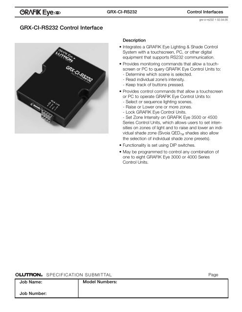
<strong>GRX</strong>-<strong>CI</strong>-<strong>RS232</strong> <strong>Control</strong> <strong>Interface</strong><br />
SPE<strong>CI</strong>FICATION SUBMITTAL<br />
Model Numbers:<br />
<strong>GRX</strong>-<strong>CI</strong>-<strong>RS232</strong><br />
<strong>Control</strong> <strong>Interface</strong>s<br />
grx-ci-rs232 1 02.04.05<br />
Description<br />
• Integrates a GRAFIK Eye Lighting & Shade <strong>Control</strong><br />
System with a touchscreen, PC, or other digital<br />
equipment that supports <strong>RS232</strong> communication.<br />
• Provides monitoring commands that allow a touchscreen<br />
or PC to query GRAFIK Eye <strong>Control</strong> Units to:<br />
- Determine which scene is selected.<br />
- Read individual zone’s intensity.<br />
- Keep track of buttons pressed.<br />
• Provides control commands that allow a touchscreen<br />
or PC to operate GRAFIK Eye <strong>Control</strong> Units to:<br />
- Select or sequence lighting scenes.<br />
- Raise or Lower one or more zones.<br />
- Lock GRAFIK Eye <strong>Control</strong> Units.<br />
- Set Zone Intensity on GRAFIK Eye 3500 or 4500<br />
Series <strong>Control</strong> Units, which allows users to set intensities<br />
on zones of light and to raise and lower an individual<br />
shade zone (Sivoia QEDTM shades also allow<br />
the selection of individual shade zone presets).<br />
• Functionality is set using DIP switches.<br />
• May be programmed to control any combination of<br />
one to eight GRAFIK Eye 3000 or 4000 Series<br />
<strong>Control</strong> Units.<br />
Page
Specifications<br />
Power<br />
Low-voltage Class 2 (PELV).<br />
Operating Voltage: 12-24 VDC.<br />
DIP Switch<br />
1<br />
2<br />
3<br />
4<br />
5<br />
6<br />
7<br />
8<br />
Job Name:<br />
Job Number:<br />
R<br />
®<br />
Function<br />
Zone Lock Retain<br />
Scene Lock Retain<br />
Sequence Retain<br />
Sequencing Scene Range<br />
Multiple Addresses 1<br />
Button Feedback<br />
Scene Status<br />
Not Used<br />
When set to ON<br />
SPE<strong>CI</strong>FICATION SUBMITTAL<br />
If power goes out, locked zones stay<br />
locked when power returns.<br />
If power goes out, locked scenes stay<br />
locked when power returns.<br />
If power goes out, sequencing resumes<br />
when power returns.<br />
Sequencing loops through scenes 5 to 16.<br />
DIP Switches 1-4 used to set address,<br />
not function.<br />
<strong>Interface</strong> reports <strong>Control</strong> Unit and<br />
Wallstation button presses.<br />
<strong>Interface</strong> reports scene changes.<br />
Model Numbers:<br />
<strong>GRX</strong>-<strong>CI</strong>-<strong>RS232</strong><br />
Uses <strong>RS232</strong> Command Set for Grafik Eye 3000/4000<br />
Monitoring: Scene selection, scene status updates, read zone intensity.<br />
<strong>Control</strong>: Scene selection, scene lockout, sequencing, zone lockout, zone raise/lower.<br />
Additional control with GRAFIK Eye 3500 or 4500 Series <strong>Control</strong> Units: Set zone intensity.<br />
System Communications and Capacity<br />
• Low-voltage Class 2 (PELV) wiring connects the <strong>Control</strong> <strong>Interface</strong> to GRAFIK Eye <strong>Control</strong> Units.<br />
• Standard 9-pin serial connector plugs into <strong>RS232</strong> equipment and the <strong>GRX</strong>-<strong>CI</strong>-<strong>RS232</strong>.<br />
• Multiple <strong>Control</strong> <strong>Interface</strong>s may be used in a single system.<br />
• 50 feet (15m) maximum from <strong>GRX</strong>-<strong>CI</strong>-<strong>RS232</strong> <strong>Interface</strong> to PC or other <strong>RS232</strong> source.<br />
Environment<br />
32-122°F (0-50°C). Relative humidity less than 90% non-condensing.<br />
Functions<br />
When set to OFF<br />
<strong>Control</strong> <strong>Interface</strong>s<br />
Power cycling unlocks locked<br />
zones.<br />
Power cycling unlocks locked<br />
scenes.<br />
Power cycling stops sequencing.<br />
Sequencing loops through<br />
scenes 1 to 4.<br />
grx-ci-rs232 2 02.04.05<br />
DIP Switches 1-4 operate as<br />
specified above.<br />
No reporting of button presses.<br />
No reporting of scene changes.<br />
1 Only for projects with more than one <strong>Control</strong> <strong>Interface</strong> that use <strong>RS232</strong> or Ethernet communications (<strong>GRX</strong>-PRG or <strong>GRX</strong>-<strong>CI</strong>-<strong>RS232</strong><br />
or <strong>GRX</strong>-<strong>CI</strong>-NWK-E). One <strong>Interface</strong> in the project automatically assumes address 16 – DIP switches do not need to be set to give it<br />
an address. (If a <strong>GRX</strong>-PRG is present, it must assume address 16.) Every other <strong>RS232</strong> or Ethernet <strong>Interface</strong> in the project must<br />
have a unique address: set DIP switch 5 to on and then use DIP switches 1-4 to assign a unique address.<br />
Page
Dimensions<br />
Class 2 (PELV)<br />
Wiring<br />
MUX Link to<br />
GRAFIK Eye<br />
<strong>Control</strong> Units and<br />
Wallstations<br />
<strong>RS232</strong> Link<br />
(to PC or AV<br />
Equipment<br />
Mounting<br />
R<br />
Job Name:<br />
Job Number:<br />
®<br />
1.06<br />
SPE<strong>CI</strong>FICATION SUBMITTAL<br />
Model Numbers:<br />
<strong>GRX</strong>-<strong>CI</strong>-<strong>RS232</strong><br />
• Mounts directly to the wall.<br />
• 19" AV rack mountable with 1U rack shelf from Lutron Model #<br />
LUT-19AV-1U.<br />
• For conduit wiring options, contact Lutron customer service.<br />
<strong>GRX</strong>-<strong>CI</strong>-<strong>RS232</strong><br />
3.75”<br />
3.75<br />
(95.3mm)<br />
1.06”<br />
(26.9mm)<br />
Wall<br />
2.50”<br />
2.50<br />
(63.5mm)<br />
5.26” 5.26<br />
(133.6mm)<br />
Mounting<br />
Holes<br />
4.26”<br />
4.26<br />
(108.2mm)<br />
DIP Switches<br />
<strong>Control</strong> <strong>Interface</strong>s<br />
Power (LED 1)<br />
grx-ci-rs232 3 02.04.05<br />
<strong>RS232</strong> Link TX<br />
(LED 4)<br />
<strong>RS232</strong> Link RX<br />
(LED 5)<br />
MUX Link TX<br />
(LED 6)<br />
MUX Link RX<br />
(LED 7)<br />
Page
<strong>RS232</strong> Link Wiring<br />
ZONE<br />
ZONE 4 CU WIRE ONLY<br />
ZONE 6<br />
HOT/LIVE<br />
SSA<br />
Job Name:<br />
CLASS 2<br />
1 2 3 4<br />
Job Number:<br />
R<br />
®<br />
USA<br />
Class 2<br />
IEC<br />
PELV<br />
ZONE 1<br />
ZONE 3<br />
ZONE 5<br />
NEUTRAL<br />
SPE<strong>CI</strong>FICATION SUBMITTAL<br />
Model Numbers:<br />
<strong>GRX</strong>-<strong>CI</strong>-<strong>RS232</strong><br />
• 9-pin to 9-pin serial cable provided.<br />
• Standard 9-pin serial connector plugs into <strong>RS232</strong> equipment,<br />
and to <strong>GRX</strong>-<strong>CI</strong>-<strong>RS232</strong>.<br />
• Must be 50 feet (15m) or less.<br />
<strong>RS232</strong> Signals<br />
Signals<br />
Com<br />
TxD<br />
RxD<br />
Pin on 9-pin Cable<br />
5<br />
3<br />
2<br />
Low-Voltage Class 2 (PELV) Wiring<br />
• Make daisy-chain connections to the low-voltage Class 2 (PELV) MUX<br />
Link terminals on the back of the <strong>Control</strong> <strong>Interface</strong>.<br />
• Do not use T-taps. Run all wires in and out of terminal block.<br />
• Each terminal accepts up to two #18 AWG (1.0mm 2) wires.<br />
• LED 1 lights (power) and LED 7 blinks rapidly (MUX Link RX) when the<br />
Class 2 (PELV) MUX Link is installed correctly and GRAFIK Eye <strong>Control</strong><br />
Unit(s) are addressed.<br />
Rear View of GRAFIK Eye <strong>Control</strong> Unit<br />
(<strong>GRX</strong>-3106 shown)<br />
Lutron Cable<br />
<strong>GRX</strong>-CBL-346S<br />
<strong>Control</strong> <strong>Interface</strong> Wiring<br />
Data Link - 4: MUX<br />
3: MUX<br />
Class 2/PELV<br />
<strong>Control</strong> wiring -<br />
2: Power<br />
1: Common<br />
COM<br />
TxD<br />
RxD<br />
<strong>RS232</strong> Link<br />
<strong>RS232</strong> Cable<br />
50 ft. (15m)<br />
Maximum<br />
MUX Link<br />
4 3 2 1<br />
<strong>Control</strong> <strong>Interface</strong>s<br />
grx-ci-rs232 4 02.04.05<br />
To PC or AV<br />
Equipment<br />
To additional Wallstations/<strong>Control</strong> <strong>Interface</strong>s<br />
(16 Maximum; three from one <strong>Control</strong> Unit<br />
without external 12VDC power supply)<br />
Page
R<br />
Job Name:<br />
Job Number:<br />
®<br />
Class 2 (PELV) Terminal Connections<br />
4 3 2 1<br />
SPE<strong>CI</strong>FICATION SUBMITTAL<br />
Model Numbers:<br />
<strong>GRX</strong>-<strong>CI</strong>-<strong>RS232</strong><br />
When used with <strong>GRX</strong>-3000 <strong>Control</strong> Units<br />
• Two #18 AWG (1.0mm2) conductors for Common (terminal 1) and 12VDC (terminal 2).<br />
Ensure that the terminal 2 connection is wired correctly. Refer to <strong>GRX</strong>-3000<br />
Specification Submittal for more details.<br />
• One shielded, twisted pair #18 AWG (1.0mm2) for data link (terminals 3 and 4).<br />
When used with <strong>GRX</strong>-4000 <strong>Control</strong> Units (See Wiring Diagram Below)<br />
• Two #12 AWG (2.5mm2) conductors for Common (terminal 1) and 24VDC (terminal 2).<br />
These will not fit in terminals. Connect as shown.<br />
• One shielded, twisted pair #18 AWG (1.0mm2) for data link (terminals 3 and 4).<br />
• Connect Drain/Shield as shown. Do not connect to Ground (Earth) or<br />
Wallstation/<strong>Control</strong> <strong>Interface</strong>s. Connect the bare drain wires and cut off the<br />
outside shield.<br />
<strong>GRX</strong>-<strong>CI</strong>-<strong>RS232</strong><br />
Data Link - (1) twisted, shielded<br />
pair #18 AWG (1.0mm 2 )<br />
3: MUX<br />
4: MUX<br />
Class 2/PELV<br />
<strong>Control</strong> wiring<br />
1: Common<br />
2: 24VDC<br />
(1) #18 AWG<br />
(1.0mm 2 )<br />
(1) #18 AWG<br />
(1.0mm 2 )<br />
D: Drain/Shield<br />
(2) #12 AWG<br />
(2.5mm 2 )<br />
(2) #12 AWG<br />
(2.5mm 2 )<br />
<strong>Control</strong> <strong>Interface</strong>s<br />
grx-ci-rs232 5 02.04.05<br />
Page